
Summary of ABB 364Gx/Ax Pressure Transmitter User
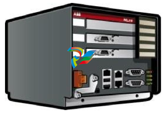
# Summary of ABB MNS iS System MLink Interface Manual (Version V7.0) This document is the interface manual for MLink, a core component of ABB MNS iS (Modular Low Voltage Intelligent Switchgear Solution). It details MLink's functions, hardware and software composition, installation and configuration, communication methods, and troubleshooting, catering to engineers needing to integrate the MNS iS system into PLCs or process control systems. I. Overview 1. Target Audience Readers are required to have basic knowledge of fieldbuses (such as PROFIBUS and Modbus), and the manual is intended for control and application engineers who need to access MNS iS system data or perform system integration. 2. Warnings and Terminology - Warning Symbols: Include warnings related to electrical safety, personal injury, and equipment damage, with strict adherence to operational specifications required. - Key Terminology: Defines core abbreviations and concepts, such as COTS (Commercial Off-The-Shelf), DCS (Distributed Control System), DTM (Device Type Manager), OPC (OLE for Process Control), and PROFIBUS-DP/V1 (fieldbus protocol). 3. Related Documents and Versions Related documents include interface manuals for various protocols (e.g., PROFIBUS, Modbus) and redundancy manuals. The content of this document corresponds to MNS iS system version V7.0, and the version history records document revision details (such as the correction of NTP server IP settings in 2014). II. Introduction to MLink and Hardware Technical Data 1. Functional Positioning** MLink is an industrial PC serving as a communication hub, enabling internal communication with MControl (supporting up to 60 units; additional MLinks are required for more than 60) and external connection to process control systems (such as DCS/PLC). 2. Hardware Types and Protocol Support** Classified into different models based on communication protocols, supported protocols include: - PROFIBUS DP/V0, DP/V1 - Modbus RTU/TCP - PROFINET IO (only supports ABB 800xA system) III. Interfaces and Hardware Layout 1. Front Panel Components - Connectors: Include switchgear bus interface (blue, for internal communication), PROFIBUS interface (black, for external communication), LAN1/LAN2 Ethernet interfaces, Modbus RTU interface, USB interfaces, etc. - LED Indicators: 8 LEDs in total, indicating power (LED7), operating status (LED1), faults (LED2), DCS communication activity (LED6), redundant master device status (LED8), etc. Different blinking combinations correspond to specific states (e.g., missing application files, configuration errors). 2. Power Connection Power is supplied through right-side terminals: Terminal 1 connects to +24V DC, and Terminal 2 connects to 0V DC. IV. Software Modules and Communication Interfaces 1. Core Software Modules - Web Server: Displays interface information on MView or browsers via the network, requiring separate activation. - OPC Server: Supports Data Access (DA) and Alarm & Event (AE), acting as a data provider for automation systems. - Fieldbus Module: Supports protocols such as PROFIBUS, Modbus, and PROFINET based on selection, requiring prior ordering of the corresponding model. - Time Synchronization: Based on the NTP protocol, supporting external NTP servers (e.g., network switches with GPS) or MLink itself as an NTP server (relying on internal RTC clock, capable of caching time for 3 hours after network disconnection). 2. Communication Networks - Internal Switchgear Network: Communicates with MControl via the switchgear bus (blue Sub-D 9 terminal), requiring proper connection of cable shields at both ends and bus termination matching the topology. - Switchgear Control Network: Connects to 10/100 Base-T Ethernet via the LAN2 interface, using CAT5 cables. It supports direct connection to MView (requiring a crossover cable) or expansion via a network switch (requiring standard network cables). The network must be protected by routers/firewalls to prevent unauthorized access. ## V. Installation and Configuration Guide 1. **Initial Parameters and Configuration Tools** - Default Parameters: LAN2 default IP 192.168.200.100, subnet mask 255.255.255.0; LAN1 default IP 192.168.100.100. DHCP is not supported, requiring manual configuration. - Configuration Tool: MNavigate software is used to set IP addresses, time synchronization methods (NTP/RTC), fieldbus parameters, etc. A restart of MLink is required for parameter changes to take effect. 2. **Installation Steps** - **Physical Installation**: Fixed in the control cable compartment of the MNS iS cubicle, secured with metal clips and screws. - **CF Card Installation**: A CF card is essential for operation, which must be configured via MNavigate before insertion into the front slot (protected by a metal cover to prevent accidental removal), with attention to the correct orientation during insertion. 3. **Startup and Redundancy Support** - Automatically starts after power-on; normal status is indicated by steady illumination of LED1 (running) and LED7 (power) after self-inspection. - Redundancy Configuration: Dual MLinks are connected via a redundancy cable for data synchronization, supporting master-slave switching, with LED8 indicating the master device status. ## VI. Troubleshooting and Maintenance 1. **LED Status Diagnosis** Different LED combinations correspond to fault types, for example: - LED2 on (fault) + LED1 off: Missing application files, requiring re-download of configuration via MNavigate. - LED2 on + XML configuration file error: Corrupted configuration file, requiring re-download of parameters. - Network configuration error: Invalid IP/gateway settings, requiring configuration check and re-download. 2. **Solutions to Common Problems** - Inaccessible MLink: Check the correctness of the IP address, network connection (verify with ping command), whether the Web server is activated, or reinsert the CF card and re-download the configuration. - MControl Communication Failure: Check switchgear bus wiring, MControl online status, and set MControl to online mode via MNavigate.
-
 Basler Electric SGC-250. Synchronous Generator Controller
 -
 Basler Electric BE1-50/51 Plug and Play and Retrofit Relays
 -
 Basler Electric DECS-2100. Digital Excitation Control System
 -
 Basler Electric DECS-250E, Digital Excitation Control System
 -
 Basler Electric BE1-700V, Voltage Only Digital Protective Relay
 -
 Basler Electric DECS-250. Digital Excitation Control System
 -
 Basler Electric DECS-450. Digital Excitation Control System
 -
 Basler Electric DECS-150. Digital Excitation Control System
 -
 Basler Electric ES-49. Temperature Relay
 -
 Basler Electric ES-81O/U, ES-81O,ES-81U Overfrequency Relay
 -
Basler Electric ES-74V, DC Voltage Sensing Relay
-
Basler Electric ES-27/59. Under/Overvoltage Relay
-
 Basler Electric ES-27. Undervoltage Relay
 -
 Basler Electric ES-25. Sync-Check Relay
 -
 Basler Electric ES-47, ES-47N Phase Sequence Relay
 -
Basler Electric ES-37.ES-37/51 Undercurrent Relay
-
 Basler Electric ES-32. Reverse Power Relay
 -
Basler Electric ES-59. Overvoltage Relay
-
 Basler Electric ES-55. Power Factor Relay
 -
 Basler Electric DGC-2020HD, Digital Genset Controller
 -
 Basler Electric BE1-FLEX, Protection, Automation, and Control System
 -
 Schneider GUTOR OC0935 Power Factor Sampling Board
 -
 Schneider GUTOR OC0922 Analog Signal Isolation Board
 -
 Schneider GUTOR OC0908 Battery Voltage Detection Board
 -
Schneider GUTOR OC0947 Temperature / IGBT Sampling Board
-
 Schneider GUTOR OP2601 Communication Expansion Board
 -
 Schneider Electric GUTOR OP2312 bypass control board
 -
 Schneider Electric GUTOR OP2130 Cooling Fan Monitoring & Control Board
 -
 Schneider Electric GUTOR OP2010 Battery Test Board / Battery Management Diagnostic Card
 -
Schneider Electric GUTOR OP2552 Three-phase Power Connection Board Assembly
-
 Schneider Electric GUTOR OP1922A Parallel Control Board / Load-Sharing Synchronization Module
 -
 Schneider Electric GUTOR OP6290B Inverter Feedback Acquisition Board / Signal Scaling Module
 -
Schneider GUTOR OP6280 Basic Signal Board
-
Schneider Electric GUTOR OP2456 / OP2456B Main control board
-
 Schneider Electric GUTOR OP2452 Power Plug-in Panel
 -
 Schneider Electric GUTOR OP2450 Parallel Communication Board
 -
Schneider Electric GUTOR OP2406 Interface Fuse Monitoring Board
-
 Schneider Electric GUTOR OC0919 High-Power Semiconductor Module
 -
 Schneider Electric GUTOR OP6281A System Logic Interface Board
 -
 Schneider Electric GUTOR OP6285A Power Signal Acquisition Board
 -
 Schneider Electric GUTOR OP2438 Fan Monitor & Drive Protection Board
 -
Schneider Electric GUTOR OP2446 Main Control CPU Board
-
 ROLLS-ROYCE CE05-00 Steering Gear Control Module
 -
 ROLLS-ROYCE MARINE AS-BRATTVAAG WRC1021A CONTROLLER CARD
 -
ROLLS ROYCE DECK MACHINERY MPC-300-A7029099 TERMINAL CONTROLLER UNIT
-
 ROLLS-ROYCE HELICON THRUSTER CONTROL PANEL LF90S-01-06
 -
 Rolls-Royce PCC1030C Panel Controller Card
 -
 Rolls-Royce RRDIO15 Remote Digital Input/Output Module
 -
 Rolls-Royce TDI-11 Pitch & Direction Indicator Module
 -
 Rolls-Royce CCN 01 CANman Controller Network Module
 -
 Rolls-Royce SLIO 01 CANman Controller Network Module
 -
 Rolls-Royce MPC-210 Winch & Propulsion Control Module
 -
Rolls-Royce MTI-144 Engine Control Module
-
 Rolls-Royce Tenfjord FB10-002 Steering Gear Module (E-4500-40-1)
 -
 ROLLS ROYCE MARINE AS CIRCUIT BOARD (PCB) RRAI016
 -
 Rolls-Royce Marine AS PIP6-1 Marine Controller
 -
 ROLLS-ROYCE MPC-300 STARTER CONTROL UNIT A7029099
 -
 Rolls-Royce Data Respons MPCF1-10.4" Maritime Panel Computer
 -
 ROLLS-ROYCE MARINE OLC-40009 PCB CARD
 -
Rolls-Royce Marine Brattvaag WRC1021B Controller Board
-
 ROLLS-ROYCE CCN 01 & ROLLS-ROYCE SLIO 02 CANMAN CONTROLLER NETWORK
 -
.png) ROLLS-ROYCE ATC-3-A7033172 AQUAMASTER TURNING CONTROLLER
ROLLS-ROYCE ATC-3-A7033172 AQUAMASTER TURNING CONTROLLER -
 ROLLS-ROYCE POSCON V.3 JOYSTICK MODULE 6459
 -
.png) Rolls-Royce Marine 389-496-00 Joystick Remote Control Panel 6799-W, 389-996-00
Rolls-Royce Marine 389-496-00 Joystick Remote Control Panel 6799-W, 389-996-00 -
 Rolls-Royce data respons 10.4'' Panel Computer 98H010A0000I/R10I53S
 -
 Rolls-Royce H1127.0101 Marine Controller 000068308
 -
 Rolls-Royce CU40-0106-50 Steering Gear Control Panel
 -
 Beckhoff Polaris CP7011-1002-0010 operator operator HMI display 30.5 cm
 -
 Beckhoff AM8052-0JH1-0000 Servomotor 10.7 Nm (M0), F5 (104 mm)
 -
 Beckhoff BX5100-0000 CANopen Bus Terminal Controller
 -
 Beckhoff CX9020-0115 PLC Module CX90200115
 -
 Beckhoff module EJ7211-0010 EtherCAT plug-in module
 -
 BECKHOFF AX5203-0000 Servo Driver
 -
 BECKHOFF CP6201-0001-0020 24VDC UNMP
 -
 Beckhoff CX5120-0135 Embedded PC CPU Module
 -
 BECKHOFF C5240-0020/000224115 Plc Module
 -
 Beckhoff CP2918-0000 nelCP29xx-0000Pa | Multi-touch built-in Control Panel with DVI/USB Extended interface
 -
 Beckhoff CX2020-0122 Embedded PC Controller
 -
 Beckhoff C6640-0040 Control Cabinet Industrial PC 7-Slot
 -
 BECKHOFF CONTROL CABINET INDUSTRIAL PC - C6930-1062-0050
 -
 Beckhoff Automation EtherCAT Terminal EK1100 EK1122
 -
Beckhoff CP6533-0001-0060 IPC
-
 Beckhoff EK9500 | EtherNet/IP™ Bus Coupler
 -
 Beckhoff CP6202-1047-0050 - An industrial-grade embedded panel computer.
 -
 Beckhoff C6650-0040 Industrial PC
 -
 BECKHOFF CX5230-0185 / 000119805 PLC Module
 -
 BECKHOFF EL4732 | EtherCAT Terminal, 2-channel analog output, voltage, ±10 V, 16 bit, oversampling
 -
 Beckhoff CP6202-0001-0010 Economy Built-In Panel
 -
 Beckhoff AX5206-0000-0202 Digital Compact Servo Drives 2-channel
 -
 Beckhoff CP6606-0001-0020 7-inch Economy Panel PC
 -
 Beckhoff CPU basic module CX2020-0155 + power supply module CX2100-0004
 -
 Beckhoff CP2913-000 Multi-Touch Display
 -
 Beckhoff CP6500-1012-0060 14250369 Control Cabinet
 -
 Beckhoff CP7902-0001-0000 Economy Control Panel with DVI/USB Extended interface
 -
 Beckhoff C6920-0010 Control cabinet Industrial PC
 -
 BECKHOFF C3640-0050 Build-in Industrial PCs
 -
 Beckhoff KL6023-0000 KL6023 EnOcean Wireless-Adapter
 -
 Kollmorgen AKM54G-ANC2DB00 servo motor
 -
 Kollmorgen AKD-P00606-NBCN-0000 Servo Drive
 -
Kollmorgen S200 Series S20350-VTS SERVO DRIVE
-
 KOLLMORGEN AKD-P00606-NBCC-I000 SERVO DRIVE
 -
 Kollmorgen MV65WKS-CE310/22PB Servo Drive Control Module
 -
 Kollmorgen S20360-VTS-021 Servo Drive
 -
 KOLLMORGEN CR06550 High-precision digital servo amplifier
 -
 KOLLMORGEN DBL5N01050-03S-VV0-S40 3-Phase AC Synchronous Brushless Servo Motor
 -
 KOLLMORGEN S70301-NANANA-024 SERVO DRIVE
 -
 Kollmorgen S20360-VTS S200 Series Servo Drive
 -
 Kollmorgen RBE-03011-A00 Brushless Frameless Servo Motor
 -
 KOLLMORGEN AKD-T00306-NBAN-0000 INPUT SERVO DRIVE
 -
 KOLLMORGEN S700 Servo Controller S70302-NANANA
 -
 Kollmorgen AKD-P00607-NBEC-0000 400/480VAC 4.40KVA Servo Drive.
 -
 KOLLMORGEN S70102-NANANA SERVO DRIVE
 -
 KOLLMORGEN AKM21E-ANSNEH02 PM Servo Motor & PRD-AMPE25EB-00 Servo Drive Array
 -
 KollMorgen SC1R06260 Servo Drive 1.4/2.2 KVA 115230 Vac
 -
 Kollmorgen AKD-P00306-NBAN-0000 Servo Drive
 -
Kollmorgen TTB2-2042-3052-A DC Motor Industrial Drive 5.5A 185 oz/in
-
 KOLLMORGEN SERVOSTAR 610-AS SERVO AMPLIFIER_SERVOSTAR610AS_S61001
 -
 KOLLMORGEN PRD-0016400P-10 & PRD-0016600D-30 Axis Control System Modules
 -
KOLLMORGEN Seidel DBL5N01700-03S-000-S40 Servo Motor
-
 Hirschmann RS20-1600M2T1SDAEHH03.1.02 Rail Switch
 -
 Hirschmann BRS30-24TX Industrial Rail Switch
 -
 Hirschmann RSPM20-4T14T1EV9HHS999.9.99 Managed Ethernet Switch
 -
 Hirschmann BELDEN RS40-0009CCCCSDAPHH09.0.14 / RS400009CCCCSDAPHH09014
 -
Hirschmann RS40 Rail Switch RS40-0009CCCCSDAE
-
 Hirschmann BELDEN RS30-0802T1T1SDAP / RS300802T1T1SDAP Fully Managed Layer 2 Compact Rail Switch
 -
 Hirschmann BELDEN RS20-0800M2M2SDAUHH / RS200800M2M2SDAUHH
 -
 Hirschmann EAGLE30-04022O6TT999SCCY9HSE3F Industrial Firewall Router Switch
 -
 Hirschmann RS20-1600T1T1SDAEHH09.0.14 RS20 Rail Mount Ethernet Switch


