
Summary of ABB 364Gx/Ax Pressure Transmitter User
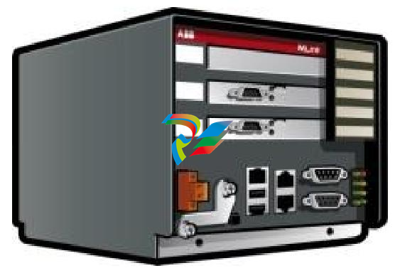
# Summary of ABB MNS iS System MLink Interface Manual (Version V7.0) This document is the interface manual for MLink, a core component of ABB MNS iS (Modular Low Voltage Intelligent Switchgear Solution). It details MLink's functions, hardware and software composition, installation and configuration, communication methods, and troubleshooting, catering to engineers needing to integrate the MNS iS system into PLCs or process control systems. I. Overview 1. Target Audience Readers are required to have basic knowledge of fieldbuses (such as PROFIBUS and Modbus), and the manual is intended for control and application engineers who need to access MNS iS system data or perform system integration. 2. Warnings and Terminology - Warning Symbols: Include warnings related to electrical safety, personal injury, and equipment damage, with strict adherence to operational specifications required. - Key Terminology: Defines core abbreviations and concepts, such as COTS (Commercial Off-The-Shelf), DCS (Distributed Control System), DTM (Device Type Manager), OPC (OLE for Process Control), and PROFIBUS-DP/V1 (fieldbus protocol). 3. Related Documents and Versions Related documents include interface manuals for various protocols (e.g., PROFIBUS, Modbus) and redundancy manuals. The content of this document corresponds to MNS iS system version V7.0, and the version history records document revision details (such as the correction of NTP server IP settings in 2014). II. Introduction to MLink and Hardware Technical Data 1. Functional Positioning** MLink is an industrial PC serving as a communication hub, enabling internal communication with MControl (supporting up to 60 units; additional MLinks are required for more than 60) and external connection to process control systems (such as DCS/PLC). 2. Hardware Types and Protocol Support** Classified into different models based on communication protocols, supported protocols include: - PROFIBUS DP/V0, DP/V1 - Modbus RTU/TCP - PROFINET IO (only supports ABB 800xA system) III. Interfaces and Hardware Layout 1. Front Panel Components - Connectors: Include switchgear bus interface (blue, for internal communication), PROFIBUS interface (black, for external communication), LAN1/LAN2 Ethernet interfaces, Modbus RTU interface, USB interfaces, etc. - LED Indicators: 8 LEDs in total, indicating power (LED7), operating status (LED1), faults (LED2), DCS communication activity (LED6), redundant master device status (LED8), etc. Different blinking combinations correspond to specific states (e.g., missing application files, configuration errors). 2. Power Connection Power is supplied through right-side terminals: Terminal 1 connects to +24V DC, and Terminal 2 connects to 0V DC. IV. Software Modules and Communication Interfaces 1. Core Software Modules - Web Server: Displays interface information on MView or browsers via the network, requiring separate activation. - OPC Server: Supports Data Access (DA) and Alarm & Event (AE), acting as a data provider for automation systems. - Fieldbus Module: Supports protocols such as PROFIBUS, Modbus, and PROFINET based on selection, requiring prior ordering of the corresponding model. - Time Synchronization: Based on the NTP protocol, supporting external NTP servers (e.g., network switches with GPS) or MLink itself as an NTP server (relying on internal RTC clock, capable of caching time for 3 hours after network disconnection). 2. Communication Networks - Internal Switchgear Network: Communicates with MControl via the switchgear bus (blue Sub-D 9 terminal), requiring proper connection of cable shields at both ends and bus termination matching the topology. - Switchgear Control Network: Connects to 10/100 Base-T Ethernet via the LAN2 interface, using CAT5 cables. It supports direct connection to MView (requiring a crossover cable) or expansion via a network switch (requiring standard network cables). The network must be protected by routers/firewalls to prevent unauthorized access. ## V. Installation and Configuration Guide 1. **Initial Parameters and Configuration Tools** - Default Parameters: LAN2 default IP 192.168.200.100, subnet mask 255.255.255.0; LAN1 default IP 192.168.100.100. DHCP is not supported, requiring manual configuration. - Configuration Tool: MNavigate software is used to set IP addresses, time synchronization methods (NTP/RTC), fieldbus parameters, etc. A restart of MLink is required for parameter changes to take effect. 2. **Installation Steps** - **Physical Installation**: Fixed in the control cable compartment of the MNS iS cubicle, secured with metal clips and screws. - **CF Card Installation**: A CF card is essential for operation, which must be configured via MNavigate before insertion into the front slot (protected by a metal cover to prevent accidental removal), with attention to the correct orientation during insertion. 3. **Startup and Redundancy Support** - Automatically starts after power-on; normal status is indicated by steady illumination of LED1 (running) and LED7 (power) after self-inspection. - Redundancy Configuration: Dual MLinks are connected via a redundancy cable for data synchronization, supporting master-slave switching, with LED8 indicating the master device status. ## VI. Troubleshooting and Maintenance 1. **LED Status Diagnosis** Different LED combinations correspond to fault types, for example: - LED2 on (fault) + LED1 off: Missing application files, requiring re-download of configuration via MNavigate. - LED2 on + XML configuration file error: Corrupted configuration file, requiring re-download of parameters. - Network configuration error: Invalid IP/gateway settings, requiring configuration check and re-download. 2. **Solutions to Common Problems** - Inaccessible MLink: Check the correctness of the IP address, network connection (verify with ping command), whether the Web server is activated, or reinsert the CF card and re-download the configuration. - MControl Communication Failure: Check switchgear bus wiring, MControl online status, and set MControl to online mode via MNavigate.
-
 AEROTECH SM Series High-Performance Stepper Motors
 -
 AEROTECH BLMSC Series Linear Motors
 -
 AEROTECH Custom Linear Motors
 -
 AEROTECH BMS Series Brushless, Slotless Rotary Motors
 -
 AEROTECH BM Series Brushless Rotary Motors
 -
 AEROTECH BLMX Series Linear Motors
 -
 AEROTECH BLMH Series Linear Motors
 -
 AEROTECH BLM Series Linear Motors
 -
 AEROTECH BLMC Series Linear Motors
 -
 AEROTECH BLMUC-143 Linear motor forcer with thermistor
 -
AEROTECH BLMUC-111 Linear motor forcer with thermistor
-
AEROTECH BLMUC-95 Linear motor forcer with thermistor
-
AEROTECH BLMUC-79 Linear motor forcer with thermistor
-
AEROTECH BLMUC Series Linear Motors
-
 AEROTECH Automation1 FLEX Distributed Amplifier Multi-Axis Servo Control System
 -
 AEROTECH Automation1 HXA4 6-Axis Hexapod Servo Drive
 -
 AEROTECH Automation1 iHXA4 6-Axis Hexapod Servo Drive with Motion Controller
 -
 AEROTECH Modular System Control Console
 -
 AEROTECH TV Series Transformers
 -
 AEROTECH TM Series Transformers
 -
 AEROTECH UFM Noise Filter Module
 -
 AEROTECH MFM Motor Filter Module
 -
 AEROTECH MPG Handwheel Pendant
 -
 AEROTECH Automation1 Multi-Axis Joystick
 -
 AEROTECH ETM Enhanced Throughput Module
 -
 AEROTECH Automation1 XL4s High-Speed, Single-Phase Linear Servo Drive
 -
 AEROTECH Automation1 XL2e Enhanced, Compact Linear Servo Drive
 -
 Automation1 iXL2e Enhanced, Compact Linear Servo Drive with Motion Controller
 -
 AEROTECH Automation1 XL5e Enhanced, Linear Servo Drive
 -
 AEROTECH Automation1 iXL5e Enhanced Linear Servo Drive with Motion Controller
 -
 AEROTECH Automation1 GI4 Laser Scan Head Controller
 -
 AEROTECH Automation1 SI4 Stepper Interface
 -
AEROTECH Automation1 XI4 Servo Interface
-
 AEROTECH AEROTECH Automation1 iXI4 Servo Interface with Motion Controller
 -
 AEROTECH Automation1 XC6e Enhanced, High-Power PWM Servo Drive
 -
 AEROTECH Automation1 iXC6e Enhanced, High-Power PWM Servo Drive with Motion Controller
 -
 AEROTECH Automation1 XC2 Compact PWM Servo Drive
 -
 AEROTECH Automation1 XC4 PWM Servo Drive
 -
 AEROTECH Automation1 GL4 Galvo Laser Scan Head Linear Drive
 -
 AEROTECH Automation1 XC2e Enhanced, Compact Servo Drive with PWM+
 -
 AEROTECH Automation1 XC4e Enhanced, PWM Servo Drive
 -
 AEROTECH Automation1 XR3 Multi-Axis Servo Drive Rack
 -
 AEROTECH Automation1 iXR3 Multi-Axis Servo Drive Rack with Motion Controller
 -
 AEROTECH Automation1 iXC2 Compact PWM Servo Drive with Motion Controller
 -
 AEROTECH Automation1 iXC2e Enhanced, Compact PWM+ Servo Drive with Motion Controller
 -
 AEROTECH Automation1 iXC4 PWM Servo Drive with Motion Controller
 -
 AEROTECH Automation1 iXC4e Enhanced, PWM Servo Drive with Motion Controller
 -
 AEROTECH Automation1 iPC Industrial PC with Motion Controller
 -
 AEROTECH EPICS & TANGO Drivers for Distributed Control Systems
 -
 AEROTECH .NET, C, Python & LabVIEW APIs Custom Application Develotpmen
 -
 AEROTECH Automation1 Industrial Ethernet Support
 -
 AEROTECH Automation1 iSMC Intelligent, Software-Based Motion Controller
 -
 AEROTECH Automation1 iXA4 1- 2- or 4-Axis PWM Servo Drive with Motion Controller
 -
 AEROTECH Automation1 XA4 1- 2- or 4-Axis PWM Servo Drive
 -
 CTI 2500-ADP2-DISC Discrete Wiring Adapter for Series 500
 -
 CTI 2500-ADP1 Analog Wiring Adapter for Series 500
 -
 CTI 2500C-RADP-RS485 Remote Base Controller Adapter for Series 500
 -
 CTI 2500C-RADP-RBC Profibus RBC Adapter for Series 500
 -
 CTI 2500C-PADP-120V 120VAC 50W Power Supply for Series 500
 -
 CTI 2500-RADP RBC Adapter for Series 500
 -
 CTI 2500-R4500 520/530/DBC Adapter for Series 500 - MATURE
 -
 CTI 2500-PADP Power Supply Adapter for Series 500
 -
 CTI 2500-IADP I/O Adapter for Series 500
 -
 CTI 2500-VP15A-N4-W7 15" Flat-Panel PC with Windows® 7 Embedded
 -
 CTI 2500S-27-1750 Slice I/O, Ethernet, RS232/485. 900MHz, 2DIO / 4UAI / 2AI
 -
 CTI 2500S-26-1750 Slice I/O, Ethernet, RS232/485. 900MHz, 8DIO / 2UAI
 -
 CTI 2500S-23-1750 Slice I/O, Ethernet, RS232/485. 900MHz, 4DI / 4DO / 2UAI / 2AO
 -
 CTI 2500S-27-1550 Slice I/O, RS232/485. 2DIO / 4UAI / 2AI
 -
 CTI 2500S-26-1550 Slice I/O, RS232/485. 8DIO / 2UAI
 -
 CTI 2500S-23-1550 Slice I/O, RS232/485. 4DI / 4DO / 2UAI / 2AO
 -
 CTI 2500S-27-1050 Slice I/O, Ethernet, 2DIO / 4UAI / 2AI
 -
 CTI 2500S-26-1050 Slice I/O, Ethernet, 8DIO / 2UAI
 -
 CTI 2500S-23-1050 Slice I/O, Ethernet, 4DI / 4DO / 2UAI / 2AO
 -
 CTI 2500C-32F-CJC 32-Pin Field Wiring Connector with Cold Junction Compensation
 -
 CTI 2500C-32F 32-Pin Field Wiring Connector
 -
 CTI 2500C-8-TC Eight Thermocouple Inputs
 -
 CTI 2500C-8-RTD Eight RTD Inputs
 -
 CTI 2500C-8-RL-FC 8 Form-C Relay Outputs
 -
 CTI 2500C-8-IDO-24V 8 Isolated 24VDC Outputs
 -
 CTI 2500C-8-IDO-120V 8 Isolated 120VAC Outputs
 -
 CTI 2500C-16-DO-24V Sixteen 24VDC Digital Outputs
 -
 CTI 2500C-16-DO-120V Sixteen 120VAC Digital Outputs
 -
.png) CTI 500C-16-IDI-24V Sixteen Isolated 24V AC/DC Digital Inputs
CTI 500C-16-IDI-24V Sixteen Isolated 24V AC/DC Digital Inputs -
 CTI 2500C-16-IDI-120V Sixteen Isolated 120V AC/DC Digital Inputs
 -
 CTI 2500C-16-DIDO-SIM Sixteen Digital Input and Output SImulator
 -
 CTI 2500C-16-DI-24V Sixteen 24V AC/DC Digital Inputs
 -
 CTI 2500C-16-DI-120V Sixteen 120V AC/DC Digital Inputs
 -
 CTI 2500C-RBC-RS485 RS485 Remote Base Controller
 -
 CTI 2500C-RBC-PRF Profibus Remote Base Controller
 -
 CTI 2500C-PS-24V-35 35-Watt DC Power Supply
 -
 CTI 2500C-PS-120V-35 35-Watt AC Power Supply
 -
 CTI 2500C-R8 Eight-Slot Base
 -
 CTI 2500C-R4 Four-Slot Base
 -
 CTI 2500C-R16 Sixteen-Slot Base
 -
 CTI 2500C-2572-B Fast Ethernet TCP/IP Adapter
 -
 CTI 2500C-J750 Compact Janus PAC with 3MB Project Memory
 -
 CTI 2500C-C300 CPU with 512K User Memory
 -
 CTI 2500C-C200 CPU with 256K User Memory
 -
 CTI 2500C-C100 CPU with 128K User Memory
 -
 CTI 2500C-8-AO 8 Analog Outputs
 -
 CTI 2500C-8-AI 8 Analog Inputs
 -
 CTI 2559-FCAL Precision Calibration Connector
 -
 CTI 2559-FPC 40-Position Screw-Terminal Connector
 -
 CTI 2500-RFC PLC to RF Modem Cable
 -
 CTI 2500-40F 40-Position Standard Screw-Terminal Connector
 -
 CTI 2505 Vibration Sensor Interface Module
 -
 CTI 2554-A 4-Channel Isolated High Speed Counter Module
 -
 CTI 2553-A 2-Channel Mag Meter Input Module
 -
 CTI 2502 2-Channel High Speed Counter Input Module
 -
 CTI 2559-TC 8-Channel Thermocouple Input Module
 -
 CTI 2556-A 16-Channel Isolated Thermocouple Input Module
 -
 CTI 2556 16-Channel Isolated Thermocouple Input Module
 -
 CTI 2551-A 8-Channel Isolated Thermocouple Input Module
 -
 CTI 2559-RTD 8-Channel RTD Input Module
 -
 CTI 2557-A 16-Channel RTD Input Module
 -
 CTI 2557 16-Channel RTD Input Module
 -
 CTI 2552-A 8-Channel Isolated RTD Input Module
 -
 CTI 2534 8-Point Form-C Relay Output Module
 -
 CTI 2532 16-Point Form-A Relay Output Module
 -
 CTI 2531 32-Point Form-A Relay Output Module
 -
 CTI 2530 8-Point Form-C Relay Output Module
 -
 CTI 2562 8-Channel Analog Output Module
 -
 CTI 2560-A 8-Channel Isolated Analog Output Module
 -
 CTI 2501 8in/4out Analog Module
 -
 CTI 2558 8-Channel Analog Input Module
 -
 CTI 2555-A 16-Channel Analog Input Module
 -
 CTI 2550-A 8-Channel Isolated Analog Input Module
 -
 CTI 2599 8/16/32-Point AC Output Module


