
ABBAdvant Fieldbus 100 User Manual
About This User Manual
General
This manual provides a general physical and functional description of
Advant Fieldbus 100 hardware and provides detailed information for installation,
service, and maintenance.
Audience
The manual is intended for ABB personnel as well as for the customers maintenance
personnel.
The reader is assumed to be familiar with the Advant Controller 70,
Advant Controller 110, Advant Controller 400 Series, AC 800M controller,
S800 I/O Stations and/or AC 100 OPC Server, the relevant data base elements, and
the Advant Station 140 Engineering Station. For further information, see Table 2.
Manual Organization
This manual contains:
• Section 1, Introduction
This section presents an overview of this document and the product it
describes, Advant Fieldbus 100.
• Section 2, Advant Fieldbus 100 Concepts
This section introduces the major concepts of the Advant Fieldbus 100
network.
• Section 3, Configuration of Advant Fieldbus 100
This section presents the configuration of the Advant Fieldbus 100.
• Section 4, Installation and Start-up
This section describes the installation and start-up procedure.
• Section 5, Maintenance and Fault Tracing
This section describes the maintenance and diagnostics.
• Appendix A, Technical Data
This appendix describes the physical features and technical data of different
communication interfaces.
• Appendix B, Low Layers of Advant Fieldbus 100
This appendix describes technical details of the low layers implementing the
AF 100 communication. The information presented is not necessary to install
and maintain a Advant Fieldbus 100 network. It merely completes the technical
description and is intended for the curious reader only.
Document Conventions
In this document, the AF 100 units are generally named without suffix Vx or A
unless it is necessary for the functionally described. CI810 is the general term for
CI810/CI810V1/CI810V2/CI810A.
For example, if media redundancy is described, and the description for S800 Field
Communication Interface (FCI) states that the unit to use is
CI810V1/CI810V2/CI810A or CI810V1, it implicitly includes CI810V2/CI810A.
For verification, refer to Table 6.
Microsoft Windows conventions are normally used for the standard presentation of
material when entering text, key sequences, prompts, messages, menu items, screen
elements, etc.
Feature Pack
The Feature Pack content (including text, tables, and figures) included in this
User Manual is distinguished from the existing content using the following
two separators:
Feature Pack functionality included in an existing table is indicated using a
table footnote (*) :
*Feature Pack Functionality
Feature Pack functionality in an existing figure is indicated using callouts.
Unless noted, all other information in this User Manual applies to 800xA Systems
with or without a Feature Pack installed.
Warning, Caution, Information, and Tip Icons
Electrical warning icon indicates the presence of a hazard which could result in
electrical shock.
Warning icon indicates the presence of a hazard which could result in personal
injury.
Caution icon indicates important information or warning related to the concept
discussed in the text. It might indicate the presence of a hazard which could
result in corruption of software or damage to equipment/property.
Information icon alerts the reader to pertinent facts and conditions.
Tip icon indicates advice on, for example, how to design your project or how to
use a certain function
This publication includes Warning, Caution, and Information where appropriate
to point out safety related or other important information. It also includes Tip to
point out useful hints to the reader. The corresponding symbols should be
interpreted as follows:
Although Warning hazards are related to personal injury, and Caution hazards are
associated with equipment or property damage, it should be understood that
operation of damaged equipment could, under certain operational conditions, result
in degraded process performance leading to personal injury or death. Therefore,
fully comply with all Warning and Caution notices.
Section 1 Introduction
Product Overview
Advant Fieldbus 100 (AF 100) is a high performance fieldbus, which is used for:
• Communication between Advant Controllers
• Communication between Advant Controllers and S800 I/O Stations, AC 800M
controllers, AC 100 OPC Server, and the equipments developed and sold by
other ABB companies.
In an AF 100 bus, it is possible to reach up to 80 stations within a total physical
distance of up to 13300 meters (43300 feet).
Advant Fieldbus supports three transmission media:
• Twisted pair (Twp)
• Coaxial (RG59 and RG11)
• Optical media.
An AF 100 bus can be built up with all the three media, where a part of one kind of
media is a specific segment.
The following rules apply to the segments:
• To each twisted pair segment, 32 stations can be connected, and the maximum
segment length is 750 meters (2500 feet)
• The coaxial segment can be:
– 300 meters (1000 feet) with cable RG59 or
– 700 meters (2300 feet) with cable RG11.
• The optical media is only used in point-to-point communication, and it allows
the total length of a bus segment to be up to 1700 meters (5500 feet).
• If back-to-back coupled optical segments are used, it is possible to reach up to a
physical length of 13300 meters (43300 feet).
An Advant Fieldbus 100 may be installed with one or two physical bus lines (single
or redundant media). Two bus lines are chosen when increased availability is
required. The redundant bus line does not enhance the bus bandwidth when both the
bus cables are operating.
Advant Fieldbus 100 Redundancy Concept
The Advant Fieldbus 100 redundancy concept contains:
• Media redundancy
• Communication interface redundancy
• S800 I/O Field Communication Interface redundancy.
When redundant media is used, redundancy must be maintained through the whole
bus (this comprises of the bus lines as well as connections of the stations to the bus).
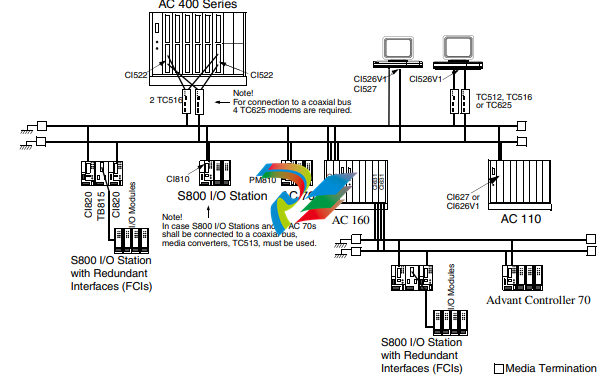
Media Redundancy
The Media redundancy includes redundant cable and redundant modems. A media
redundant AF 100 is configured and connected as in Figure 1.
The maximum difference in cable length between the redundant cables must be less
than 1200 meters between any two stations throughout the whole bus.
Figure 1. An Advant Fieldbus 100 configuration using redundant media
If the Advant Fieldbus 100 contains one or more of CI520, CI526, CI626, CI810
or PM810 (without the suffix Vx(1)
(1) V1, V2, V3, and so on
or y(2)
(2) y=A, B, and so on
), it is only possible to use redundant
coaxial media with a maximum difference of four meters in cable length, between
any two stations on the bus. A redundant Twisted Pair or Optical media cannot be
used in this case.
Communication Interface Redundancy Section 1 Introduction
28 3BSE000506-600
Communication Interface Redundancy
Communication interface redundancy is achieved by using a pair of CI522s, CI630s,
CI631s, CI869s or CI820s, connected to a media redundant bus. Communication
interface redundancy is available for Advant Controller 400 Series, Advant
Controller 160, AC 800M controller, and S800 I/O stations.
Two communication interfaces (CIs) can operate as a pair, where one is Primary and
the other is Backup in the controller configuration.
Functions of Primary CI
In a redundant configuration, the address of the primary CI is the configured station
address on the bus.
The primary CI:
• Sends all output CDPs.
• Receives all input CDPs.
• Sends the time synchronization message if the station is configured as time
synchronization master.
• Handles the normal Service Data communication for the station.
• Supervises that the backup can send on the bus. This is done at a low frequency
using the service data protocol.
• Must be configured as bus master if the module is CI522/CI630 or CI631, so
that the bus master responsibilities are performed
Functions of Backup CI
In a redundant configuration, the address of the backup CI on the bus is the
configured station address + 80.
The backup CI:
• Supervises that the primary CI sends its output CDPs properly.
• Sends signal to the controller if the primary CI does not send its output CDPs.
• Receives all input CDPs.
• Responds to Service Data communication with the Primary.
• Must be configured as bus master if the module is CI522, CI630 or CI631. If
the station number is less than or equal to 47, the backup module performs the
bus master responsibilities, otherwise it does not.
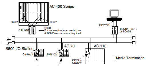
Communication Interface Redundancy in Advant Controller 400 Series
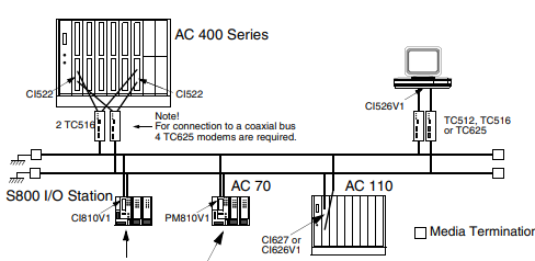
To connect the CI522 redundant communication interfaces to a twisted pair bus, two
TC516 modems (or four TC512 modems) are used. See Figure 2.
To connect the CI522 redundant communication interfaces to a coaxial cable bus,
four TC625 modems are required.
The TC516 modem has two connections, one for each redundant CI522 and a
connection to one twisted pair bus cable. TC516 can be used for two redundant
CI522s as well as for one single CI520V1/CI522/CI526V1.
If communication interface redundancy is used, set the DB-element for
double time-out. See Double CDP Time-out on page 88.
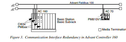
Communication Interface Redundancy in Advant Controller 160
For configurations with one Advant Fieldbus 100, the communication interface
CI630/CI631 must be placed at position 2 (non redundant interface) or in position 1
and 2 (redundant interface) in the Basic Station.
A second and third Advant Fieldbus 100 can be used with AC 160. These can use
single or redundant communication interfaces. The communication interfaces can
be placed at position 9 and 10, or 11 and 12, and so on.
S800 I/O Field Communication Interface Redundancy
The redundancy in the S800 I/O Stations is achieved with redundant Field
Communication Interfaces (FCIs) connected to a media redundant
Advant Fieldbus 100. In the S800 I/O station, redundancy is achieved with
redundant S800 communication interfaces sharing the same I/O modules. This
redundancy follows the same principles as the communication interface redundancy
in the Advant Controller 400 Series.
Communication Interface Redundancy in AC 800M
The communication interface redundancy in AC 800M is achieved by using two
CI869 modules that are connected to the same AC 800M controller. One of the
CI869 modules is configured as primary, while the other is configured as backup.
Failover time for CI869 and Double DSP timeout
The failover time is the time that the backup CI869 takes to function as primary
without error, if the primary CI869 does not work properly.
The other stations on the AF 100 bus do not influence the failover of the CI869
modules.
The backup CI869 is supervising that the primary CI869 is sending its CDPs with
the expected cycle time. If the backup CI869 detects that the Primary CI869 does
not send its CDPs as it should, it triggers the AC 800M controller to perform a
failover of CI869.
The ‘Double DSP timeout’ parameter must be enabled for an AF 100 station that is
receiving DSP data from another AF 100 station that uses redundant communication
interfaces. For details, refer to the Online Help of Control Builder.
Cable Redundancy and Partner Supervision
In a redundant configuration, the primary and the backup CI869 modules supervise
that the communication happens between them.
The backup CI869 supervises that the primary CI869 sends its CDPs as it should.
For this, it is required that both the cables that are connected to the backup CI869
have bus traffic.
If any of the cables connected to the backup CI869 are without bus traffic for 10 ms
or more, the Partner Supervision is disabled, and:
• If the parameter "Cable" on the CI869 hardware editor is set to Redundant, the
Partner Supervision not active unit status bit is set on the backup
CI869 hardware unit.
• If the parameter “Cable” is not set to Redundant, the status bit is not set.
However, a warning stating that the Partner Supervision requires redundant
lines is displayed during the download of this redundant CI869 configuration to
the controller.
Advant Fieldbus 100 Length Concept
The Advant Fieldbus 100 length concept helps to configure the bus for three
different lengths and thereby achieve different combinations of physical distance
and performance.
The possible lengths for AF 100 bus are:
• 2000 meters (6500 ft., maximum physical distance is 1700 meters).
• 8500 meters (27600 ft., maximum physical distance is 7600 meters). The
throughput must be 40% of the throughput on 2000 meters.
• 15000 meter (48750 ft., maximum physical distance is 13300 meters). The
throughput must be 15% of the throughput on 2000 meter.
The Advant Fieldbus 100 bus length is set while defining the communication
interface.
See Section 2, Advant Fieldbus 100 Concepts, for detailed rules of how to calculate
bus length in an Advant Fieldbus 100 network. See Section 3, Configuration of
Advant Fieldbus 100 for calculation of performance and bus load.
Figure 5 shows an example of an Advant Fieldbus 100 network with length of
15000 meters
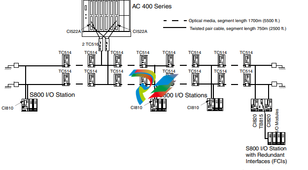
Figure 5. An example of using the Advant Fieldbus 100 length concept for 15000
meter.
In Figure 5, the necessary terminations and groundings are not shown completely.
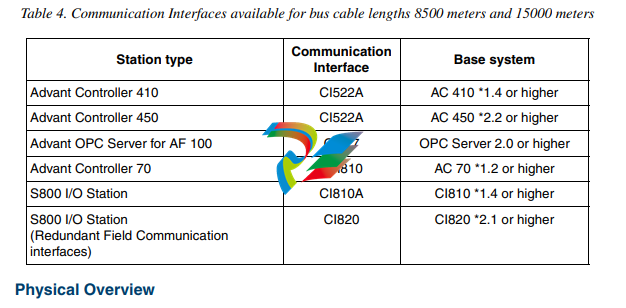
Table 4 describes the communication interfaces that support the bus lengths of
8500m (27630 ft.) and 15000m (48750 ft.).
Physical Overview
General
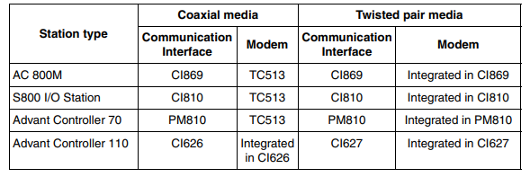
A station is connected to the AF 100 bus through a communication interface and a
particular modem. Table 5 describes the communication interfaces and modems that
are used for the different station types and media.
Table 5. Communication Interfaces and modems for different station types and media
The allowed station numbers for Advant Controller 400 Series and
AC 100 OPC Server are 1 to 80. For other controllers and AF 100 Stations, station
numbers 1 to 79 are allowed.
Communication Interfaces
There are several communication components that can communicate on the
Advant Fieldbus 100. The communication interfaces that have the capability to be
Bus Administrators are CI520, CI522, CI525, CI526, CI527, CI626, CI627, CI630,
and CI631.
Advant Controller 70
The Advant Controller 70 has integrated Twisted Pair Modems for connection to
Advant Fieldbus 100.
Advant Controller 110
The Advant Controller 110 is connected to the Advant Fieldbus 100 via a CI626
communication interface for coaxial media or a CI627 communication interface for
twisted pair media.
Advant Controller 160
The Advant Controller 160 is connected to the Advant Fieldbus 100 via a CI626 or
CI630 communication interface for coaxial media or a CI627 or
CI631communication interface for twisted pair media.
Advant Controller 400 Series
The Advant Controller 400 Series is connected to the Advant Fieldbus 100 via
single CI520 or via single or redundant CI522 communication interface, and
modem TC625 for coaxial media or modem TC512/TC516 for twisted pair media.
AC 800M
The AC 800M controller is connected to the Advant Fieldbus 100 through single or
redundant CI869 communication interfaces. The CI869 has integrated twisted pair
modems.
The CI869 module along with AC 800M controller does not function as
bus administrator on the AF 100 bus. If this station is used, the AF 100 bus requires
another station type that functions as bus administrator.
S800 I/O Station
The S800 I/O Station has integrated Twisted Pair modems for connection to
Advant Fieldbus 100.
AdvaSoft for Windows
AdvaSoft for Windows is connected to Advant Fieldbus 100 through a CI526
communication interface and a modem – TC625 (for coaxial media) or
TC512/TC516 (for twisted pair media).
Advant OPC Server for Advant Fieldbus 100 and AC 100 OPC Server
The OPC Server is connected to Advant Fieldbus 100 through a CI526 or a CI527
communication interface.
When using CI526, one or two TC625 modems (for coaxial media) or
TC512/TC516 modems (for twisted pair media) are required.
The CI527 has two integrated Twisted Pair modems. When CI527 is to be connected
to coaxial media, a TC513 repeater modem for each bus line is used for media
conversion.
CI626/CI6301 Communication Interface
The Advant Controller 110 is connected to the Advant Fieldbus 100 through a
CI626 communication interface. The Advant Controller 160 is connected to Advant
Fieldbus 100 through a CI626 or CI630 communication interface (see Figure 11 and
Figure 12).

-
 Hirschmann RS20-1600M2T1SDAEHH03.1.02 Rail Switch
 -
 Hirschmann BRS30-24TX Industrial Rail Switch
 -
 Hirschmann RSPM20-4T14T1EV9HHS999.9.99 Managed Ethernet Switch
 -
 Hirschmann BELDEN RS40-0009CCCCSDAPHH09.0.14 / RS400009CCCCSDAPHH09014
 -
Hirschmann RS40 Rail Switch RS40-0009CCCCSDAE
-
 Hirschmann BELDEN RS30-0802T1T1SDAP / RS300802T1T1SDAP Fully Managed Layer 2 Compact Rail Switch
 -
 Hirschmann BELDEN RS20-0800M2M2SDAUHH / RS200800M2M2SDAUHH
 -
 Hirschmann EAGLE30-04022O6TT999SCCY9HSE3F Industrial Firewall Router Switch
 -
 Hirschmann RS20-1600T1T1SDAEHH09.0.14 RS20 Rail Mount Ethernet Switch
 -
 Hirschmann EAGLE0200T1T1TDDY90000HHE05.3.03 Industrial Security Router
 -
Hirschmann - BELDEN MIPP-AD-1L9P
-
 HIRSCHMANN RSPM20-4Z64Z6TV9HHS9 942 106-999 RAIL SAFETY SWITCH
 -
 HIRSCHMANN FIBEROPTIC MODULE FIP P/N: OZDFIPG3T
 -
 HIRSCHMANN RS20-1600M2M2SDAUHH Ethernet rack-mounted switch
 -
 HIRSCHMANN BELDEN RS20-0400T1T1SDAEHH04.0.01 / RS200400T1T1SDAEHH04001
 -
HIRSCHMANN MM2-4FXM3 MICE Media Module
-
HIRSCHMANN RS20-0800M2M2SDAE Industrial Ethernet Rail Switch
-
 Hirschmann RS20-2400T1T1SDAP / RS20-2400T1T1SDAPHH05.0.02
 -
 GE MLJ1005B010H00C MLJ Digital Synchromism Check
 -
 ALSTOM MICROTECH DX21-M2 Digital Excitation Controller
 -
HIRSCHMANN BRS20-1200ZZZZ-STCY99HHSES
-
 HIRSCHMANN MM3-4FXM2 MICE Media Module
 -
Hirschmann RSB20-0800T1T1SAABHH 8Port ENet Rail Switch RSB20
-
 Hirschmann MACH102-8TP Ethernet Switch
 -
 SAACKE DDZ-M marine steam pressure atomizer
 -
 SAACKE SKV-A marine rotary cup atomizer
 -
 SAACKE Seavis HMI05e
 -
 Kollmorgen MMC-SD-2.0-230 Servo Drive 100-240VAC 2KW 10A Output 3PH 100-240VAC
 -
 Kollmorgen Servo drive CR10550
 -
 Kollmorgen AKD-P01207-NACN-0054 Servo Driver
 -
 Kollmorgen S406M-CA-036 Servostar
 -
.png) Kollmorgen AKD-B02407-NAAN-0000 Digital Servo Drive
Kollmorgen AKD-B02407-NAAN-0000 Digital Servo Drive -
 Kollmorgen SERVOSTAR S406AM-CA Digital Servo Drive
 -
 KOLLMORGEN SERVOSTAR 603-AS SERVO AMPLIFIER_SERVOSTAR603AS_S60301
 -
Kollmorgen S700 Servo Controller (S70602-NANANA-NA)
-
 Kollmorgen MPK411 controller
 -
 KOLLMORGEN MMC-SD-1.3-460-D Smart Drive
 -
 KOLLMORGEN AKM21C-CKB2AA-00 / AKM21CCKB2AA00 Servomotor
 -
 BECKHOFF AX5106-0000-0200 | Digital Compact Servo Drives 1-channel
 -
 BECKHOFF C3620-0000 INDUSTRIAL COMPUTER (MOTORSHELVES)
 -
 Beckhoff EK1960-0000 TwinSAFE Compact Controller
 -
 Beckhoff C6930-0050 Control Cabinet Industrial PC
 -
 Beckhoff CP7711-0001-0030 Industrial Computer Detection
 -
 Beckhoff CX1001-0111 Embedded PC CPU Module
 -
 Beckhoff C6017-0020 | Ultra-compact Industrial PC
 -
 Beckhoff EK1322 | 2-port EtherCAT P junction with feed-in
 -
 Beckhoff CP2219-0010 Panel
 -
 BECKHOFF C6015-0020 ULTRA COMPACT INDUSTRIAL PC
 -
 BECKHOFF CX2030-0120/Standard CPU Module Embedded PC Windows PLC controller
 -
 Beckhoff CP7721-1090-0020 Panel PC
 -
 Beckhoff PC CPU Module CX5130-0175
 -
 Beckhoff C6920-0050 Control Cabinet
 -
 Beckhoff EL6631 EtherCAT 2-Port Communication Interface, Profinet RT Controller
 -
 Beckhoff CP6202-0001-0060 touch screen panel PC
 -
 Beckhoff CP3916-1002-0000 Multi-Touch Control Panel
 -
 Beckhoff EP1809-0021 | EtherCAT Box, 16-channel digital input, 24 V DC, 3 ms, M8Preferred type
 -
 Beckhoff CX8190 PLC Embedded Industrial PC Ethernet Controller
 -
 Beckhoff CX2100-0914 Power Supply for External
 -
 Beckhoff Automation CP6906-0001-0000 HMI
 -
 Beckhoff EP7342-0002 Module
 -
 Beckhoff CX1020-0112 / CX1100-0910 / CX1020-N010 / CX1100-0003 Windows CPU
 -
 Beckhoff EP7211-0034 EtherCAT Box 1 Channel Motion Interface
 -
 Beckhoff C6240-0030 Control cabinet Industrial PC
 -
 beckhoff motherboard CB1052-0004 CB1052-0004
 -
 Beckhoff AX2006-AS Servo Drive / Variable Frequency Drive
 -
BECKHOFF CP6207-0001-0020 NSMP
-
 Beckhoff C6930-1142-0060 Industrial Computer
 -
 Beckhoff FC7501-0000 interface card
 -
 Beckhoff CX5140-0175 Embedded PC PLC CPU CX5140 Industrial Controller
 -
 Beckhoff CP7802-1100-0010: High-End IP65 Control Panel with DVI/USB Extended Interface
 -
BECKHOFF CP3716-1058-0010 CONTROL PANEL
-
 Beckhoff AX8108-0000 Single-Axis Module
 -
 Beckhoff CU8851-0000 | USB extension, USB Extended 2.0 receiver box
 -
Beckhoff C6017-0030 | Ultra-compact Industrial PC
-
 Beckhoff CX1001-0120/CX10010120.cx1000-n001.cx1000-n000 System Overview
 -
 Beckhoff CPU Module CX5140-0155/4GB CPU Module
 -
 Beckhoff CP6533-0001-005: Built-in Panel PC with High-Definition Multi-Touch Control
 -
 Beckhoff EL5042 | EtherCAT Terminal, 2-channel encoder interface, BiSS® C
 -
 Beckhoff C6920-1080-0040: Premium Control Cabinet Industrial PC
 -
 Beckhoff C6920-0060 | Control cabinet Industrial PC
 -
 Beckhoff Embedded-PC CX5010-1121
 -
 Beckhoff CB3050-0010 Mainboard Motherboard
 -
 Beckhoff PLC module CX1020-0000 Basic CPU module (service phase)
 -
 Beckhoff CP7812-1056-0010 15" Multitouch Display Control Panel
 -
 Beckhoff CX5120-0115 /2GB Controller Module
 -
 Beckhoff CP7201-1000-0000 Industrial Panel PC
 -
 Beckhoff Servo Motor AM8061-0JH1-0000
 -
 BECKHOFF CP6503-0001-0050 Built-in Panel PC
 -
Beckhoff CP3919-0010 Display G190ETN01.2 19" PCT V04. Multi-touch Control Panel
-
 Beckhoff CX5110-0112-9020/000368201 Embedded PC Intel Atom Processor
 -
 Beckhoff AX8206-0000 Dual-Axis Module
 -
Beckhoff Nail Operating Terminal CP7032-1031-0010
-
Beckhoff AM8042-0EH1-0000 Servomotor 4.10 Nm (M0), F4 (87 mm)
-
 Beckhoff EK9300 Beckhoff CPU Module
 -
Beckhoff CP3224-0020 Multitouch-Panel-PC
-
 Beckhoff CP2712-0000 12.1" 24VDC Touch Screen WMD0
 -
 BECKHOFF CX5240-0195 / 0000289234 Embedded PC 40 GB CFast Card
 -
 Beckhoff CP6932-1000-0000 Control Panel
 -
 BECKHOFF CX5120-0121 PLC Module
 -
 Beckhoff EL3218 | EtherCAT Terminal, 8-channel analog input
 -
Beckhoff C6640-0050 | Control cabinet Industrial PC
-
 Beckhoff Cx5130-0120/4GB Embedded-PC
 -
 BECKHOFF CX2030-0122 PLC PROCESSOR
 -
 BECKHOFF CX5020-0122 Controller Module
 -
 Beckhoff CP3915-0000 Multitouch Panel
 -
 BECKHOFF EL3014 | EtherCAT Terminal
 -
 BECKHOFF Industrial Computer c6920-1057-0030
 -
 Beckhoff CX5130-0141/4GB CX5130-0141 Embedded PC
 -
 Beckhoff C6240-1052-0040 4-086-06-3073 Industrial Computer
 -
 Beckhoff CX5140-0135 /4GB High-Performance Embedded Industrial PC
 -
 Beckhoff C6515-1001-0000 Industrial PC
 -
 Beckhoff AX5103-0000-0200 - Digital Compact Servo Drives
 -
 Beckhoff CX2030-0130-1003/4GB Basic CPU module
 -
 Beckhoff AX8620-0000 Power Supply Module
 -
 Beckhoff CX9020-0111 module with
 -
 Beckhoff EL7332 PLC Module
 -
 BECKHOFF CP7709-0001-0020 HMI
 -
 Beckhoff CX5120-0155/2GB Embedded PC
 -
 BECKHOFF CP7037-1037-0010 OPERATOR INTERFACE TOUCHSCREEN
 -
 Beckhoff EK9000 | ModbusTCP/UDP Bus Coupler
 -
 Beckhoff Touch Panel Screen CP6020 -0000-0000
 -
 Beckhoff CX2020-0121 Module FAST Shipping
 -
 Beckhoff CX2030-0125 Basic CPU Module
 -
 Beckhoff CP3918-0000 Multi-Touch 18.5" Control Panel
 -
 Automotion LC4A00010 DC BL Motor Control, ATS, Sub Assy, SCP, 115VAC,
 -
 500T-115VAC - VAS ENGINEERING - DORIC 500 SERIES DIGITAL TEMP INDICATOR
 -
 Honeywell X-DCS2000/EN Digital Integrated System Manager 50/60Hz 100-240V #4
 -
 Kollmorgen S60600 Servostar600 606-Fan 4 kVA, 6 A, 3 X 230 - 480 V


