
A-BPowerFlex 700 Adjustable Frequency AC Drive
Product Overview
The PowerFlex® 700 AC drive offers outstanding performance in an easy-to-use drive that you have come to
expect from Rockwell Automation. The PowerFlex 700 AC drive is designed to control three-phase induction
motors in applications with requirements ranging from the simplest speed control to the most demanding
torque control. The drive has volts per hertz, sensorless vector, and vector control. Vector control includes
Allen-Bradley’s patented Force Technology, which provides world class motor control.
Flexible Packaging and Mounting
• IP20, NEMA / UL Type 1 – For conventional mounting inside or outside a control cabinet. Conduit plate is removable for easy
installation and replacement without disturbing conduit.
• IP54, NEMA / UL Type 12 – standalone, wall mount drives are available for dust-tight applications with power ratings 75...200 Hp
(Frames 5 and 6).
• IP54, NEMA / UL Type 12 – Flange mount drives with an IP00, NEMA / UL Type Open front. These can be installed in a user supplied
cabinet to meet IP54, NEMA / UL Type 12. This allows most heat to be exhausted out the back of the cabinet while keeping the cabinet
protected. Power ratings range 75...200 Hp (Frames 5…6).
• Zero-Stacking™ Drive– Frame 0…6 drives can be mounted next to each other with no reduction of surrounding air temperature rating 50 °C (122 °F). This unique bookshelf design also allows access to one drive without disturbing another.
• Conformal Coating - The drive is coated in an insulator, or non-conducting substance, that helps protect it from moisture, fungus,
dust, corrosion, abrasion, and other environmental stresses caused by highly polluted atmospheres. The coating improves product
lifetime expectancy when exposure to corrosive environment is present. It helps maintain long-term surface insulation resistance,
ensuring operational integrity of the assembly.
Space Saving Hardware Features
• Integral EMC Filtering plus built-in DC bus choke common mode cores and common mode capacitors provides a compact, all-in-one
package solution for meeting EMC requirements. Frames 0…6 only.
• Internal Communications allows you to integrate the drive into the manufacturing process. Status indicators for all internal
communication options are visible on the cover for easy setup and monitoring of drive communications. You can easily manage
information from shop floor to top floor and seamlessly integrate their complete system as they control, configure, and collect data.
• Integral Dynamic Brake Transistor delivers a cost-effective means of switching regenerative energy without costly external
chopper circuits. These internal transistors are available in power ratings 0.5...200 Hp.
• Internal Dynamic Brake Resistor (up to 25 Hp) requires no extra panel space, and supplies a large amount of braking torque for
short periods.
Easy to Use Human Interface Tools
The PowerFlex 7-Class AC drives provide common Human Interface tools that are familiar and easy to use. These include the LCD Human
Interface modules and PC-based configuration tools.
Human Interface Module
The LCD Human Interface modules provide:
• Large and easy to read 7 line x 21 character backlit display
• Variety of languages (English, French, German, Italian, Spanish, Portuguese, Dutch)
• Alternate function keys for shortcuts to common tasks
• “Calculator-like” number pad for fast and easy data entry (Full Numeric version only)
• Control keys for local start, stop, speed, and direction
• Remote versions for panel mount application
Connected Components Workbench Software
Connected Components Workbench™ programming and configuration software leverage proven Rockwell Automation and Microsoft® Visual
Studio® technologies for fast and easy drive configuration, controller programming, and integration with the HMI editor.
The workbench includes:
• an intuitive interface and startup wizards
• localized language support
• online and offline configuration
• context-sensitive help
• supports PowerFlex drives, Micro800™ programmable controllers, and PanelView™ component graphic terminals
Outstanding Control and Performance
Multiple motor control algorithms allow performance that is matched to the application need:
• Volts/Hertz for simple Fan and Pump applications.
• Sensorless Vector for high torque production over a wide speed range.
• Vector for outstanding torque regulation and excellent low speed/zero speed
performance (w/Vector Control cassette).
The PowerFlex 700 drive's Vector Control uses Allen-Bradley's patented Force Technology
which provides excellent low-speed performance - whether it is operated with or without
feedback. While this industry-leading control provides the highest level of drive performance,
it is as easy to use as any general-purpose drive available.
Drives Features
• Fast-acting Current Limit and Bus Voltage Regulation result in maximum accel/decel without tripping.
• High-speed analog inputs improve drive response to torque or speed commands.
• Programming flexibility allows parameters to be linked within the drive.
• Flying Start delivers smooth and instantaneous connection into rotating loads, regardless of commanded direction, without the need
for any speed feedback.
• Integral Process PI Control can eliminate the need for a separate process loop controller.
• Inertia Ride-Through offers tripless operation during a prolonged power outage by using the rotating energy that is stored in high
inertia, low-friction loads.
• Position Indexer/Speed Profiler uses a 16-step indexer to provide point-to-point positioning or velocity profiling based on encoder
counts, digital inputs, parameter levels, or time.
• TorqProve™ assures control of the load when transferring control between the drive and a mechanical brake.
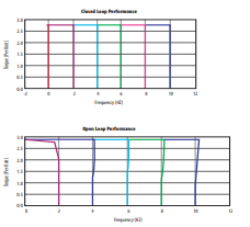
• Speed Regulation - Open Loop or Closed Loop
- Slip Compensation delivers a minimum 0.5% speed regulation without feedback hardware.
- Droop allows drives to load share without fighting each other.
- Encoder Feedback provides up to 0.001% speed regulation for the tightest application requirements.
• Torque Regulation - Open Loop or Closed Loop
- Open Loop torque regulation provides 5% regulation.
- Encoder Feedback provides 2% regulation and the ability to hold full load at zero speed.
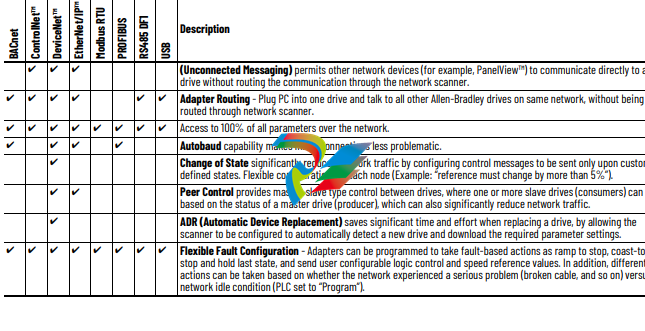
Unsurpassed Capability in Network Communications
PowerFlex drives are fully compatible with the wide variety of Allen-Bradley DPI™ communication adapters, offering the following benefits:
Drive, Fuse, and Circuit Breaker Ratings
The PowerFlex 700 can be installed with input fuses or an input circuit breaker. National and local industrial safety regulations and/or
electrical codes can determine additional requirements for these installations.
The tables on the following pages provide recommended AC line input fuse and circuit breaker information. See Fusing and Circuit Breakers
below for UL and IEC requirements. Sizes that are listed are the recommended sizes based on 40 °C (104 °F) and the U.S. NEC. Other country,
state, or local codes can require different ratings. Tables with DC link fuse recommendations for DC input drives are also provided.
Fusing
The recommended fuse types are listed below. If available current ratings do not match those listed in the tables that are provided, choose
the next higher fuse rating.
• IEC – BS88 (British Standard) Parts 1 and 2, EN60269-1, Parts 1 and 2(1), type gG or equivalent must be used.
• UL – UL Class CC, T, RK1, or J must be used for Frames 0…6.
Circuit Breakers
The “non-fuse” listings in the following tables include inverse time circuit breakers, instantaneous trip circuit breakers (motor circuit
protectors) and 140M Motor Protection Circuit Breakers (MPCBs) that are rated for use as self-protected combination motor controller
(Frames 0…6 only). If one of these is chosen as the desired protection method, the following requirements apply:
• IEC – Both types of circuit breakers and 140M self-protected combination motor controllers (Frames 0…6 only) are acceptable for IEC
installations.
• UL – Only inverse time circuit breakers and the specified 140M self-protected combination motor controllers (Frames 0…6 only) are
acceptable for UL installations.
Circuit Breaker - inverse time breaker. For US NEC, minimum size is 125% of motor FLA. Ratings that are shown are maximum.
(5) Motor Circuit Protector - instantaneous trip circuit breaker. For US NEC, minimum size is 125% of motor FLA. Ratings that are shown are maximum.
(6) Bulletin 140M devices with adjustable current range must have the current trip set to the minimum range that the device does not trip.
(7) Manual Self-Protected (Type E) Combination Motor Controller, UL Listed for 208V Wye or Delta, 240V Wye or Delta, 480Y/277V or 600Y/347V. Not UL Listed for use on 480V or 600V Delta/
Delta, corner ground, or high-resistance ground systems.
(8) The A1C ratings of the Bulletin 140M devices can vary. See publication 140-TD005 or 140M-TD002.
(9) Maximum allowable rating by US NEC. Exact size must be chosen for each installation.
(10) UL Type 12/IP54 (flange mount) heat sink ambient temperature rating is 40° C/ambient of unprotected drive portion (inside enclosure) is 55° C. The ambient temperature for the UL Type 12/
IP54 standalone drives is 40° C.
(11) Must remove top label and vent plate, drive enclosure rating is IP00, NEMA / UL Type Open.
(12) Frames 0…4 temperature rating is for NEMA / UL Type Open. The adhesive top label must be removed to operate drive at this temperature. Frames 5 and 6 do not have a top label.
(13) Drives have dual current ratings; one for normal duty applications, and one for heavy-duty applications. The drive can be operated at either rating.
(14) Note: 600V class drives below 77 amps (Frames 0…4) are declared to meet the Low Voltage Directive and UK Low Voltage Regulations. It is the responsibility of the user to determine
compliance to the EMC Directive and UK EMC Regulations.
(15) When using a Manual Self-Protected (Type E) Combination Motor Controller, the drive must be installed in a ventilated or non-ventilated enclosure with the minimum volume that is specified
in this column. Application-specific thermal considerations can require a larger enclosure.
(16) Temperature rating is for IP20, NEMA / UL Type 1. For IP00, NEMA Type Open the temperature rating is 65 °C for the control board and 40 °C for the heat sink entry air.
(17) 40 °C = 104 °F; 45 °C = 113 °F; 50 °C = 122 °F; 55 °C = 131 °F
Cable Recommendations
Power Cable Types Acceptable for 200…600 Volt Installations
Various cable types are acceptable for drive installations. For many installations, unshielded cable is adequate, provided it can be separated
from sensitive circuits. As an approximate guide, allow a spacing of 0.3 meters (1 foot) for every 10 meters (32.8 feet) of length. In all cases,
long parallel runs must be avoided. Do not use cable with an insulation thickness less than or equal to 15 mils (0.4mm/0.015 in.). Use Copper
wire only. Wire gauge requirements and recommendations are based on 75 °C (167 °F). Do not reduce wire gauge when using higher
temperature wire. See table below.
Unshielded
THHN, THWN or similar wire is acceptable for drive installation in dry environments provided adequate free air space and/or conduit fill rates
limits are provided. Do not use THHN or similarly coated wire in wet areas. Any wire that is chosen must have a minimum insulation
thickness of 15 mils and should not have large variations in insulation concentricity.
Shielded/Armored Cable
Shielded cable contains all general benefits of multi-conductor cable with the added benefit of a copper braided shield that can contain
much of the noise that is generated by a typical AC drive. Strong consideration for shielded cable should be given in installations with
sensitive equipment such as weigh scales, capacitive proximity switches and other devices that may be affected by electrical noise in the
distribution system. Applications with large numbers of drives in a similar location, imposed EMC regulations or a high degree of
communications/ networking are also good candidates for shielded cable.
Shielded cable may also help reduce shaft voltage and induced bearing currents for some applications. In addition, the increased impedance
of shielded cable may help extend the distance that the motor can be located from the drive without the addition of motor protective devices
such as terminator networks.
Consideration should be given to all general specifications that are dictated by the environment of the installation, including temperature,
flexibility, moisture characteristics and chemical resistance. In addition, a braided shield should be included and be specified by the cable
manufacturer as having coverage of at least 75%. An additional foil shield can greatly improve noise containment.
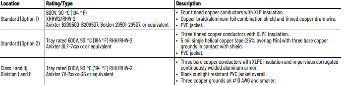
A good example of recommended cable is Belden 295xx (xx determines gauge). This cable has four (4) XLPE insulated conductors with a
100% coverage foil and an 85% coverage copper braided shield (with drain wire) surrounded by a PVC jacket.
Other types of shielded cable are available, but the selection of these types may limit the allowable cable length. Particularly, some of the
newer cables twist four conductors of THHN wire and wrap them tightly with a foil shield. This construction can greatly increase the cable
charging current required and reduce the overall drive performance. Unless specified in the individual distance tables as tested with the
drive, these cables are not recommended and their performance against the lead length limits supplied is not known.
Maximum Motor Cable Lengths
For information on maximum motor cable lengths, see the Wiring and Grounding Guidelines for Pulse Width Modulated (PWM) AC Drives,
publication DRIVES-IN001.
Power Wiring
The PowerFlex 700 has the following built in protective features to help simplify installation:
• Ground fault protection during startup and running ensures reliable operation
• Electronic motor overload protection increases motor life
• Removable MOV to ground and common mode capacitors to ground ensure compatibility with ungrounded systems. These devices
must be disconnected if the drive is installed on a resistive grounded distribution system, an ungrounded distribution system, a B
phase grounded distribution system or impedance grounded system. These devices must also be disconnected if the drive power
source is a regenerative unit (such as a bus supply and brake) or is DC fed from an active converter.
• 6 kV transient protection provides increased robustness for 380…480V system voltages
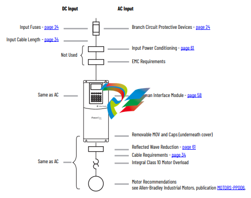
There are many other factors that must be considered for optimal performance in any given application. The block diagram below highlights
the primary installation considerations. Consult the Wiring and Grounding Guidelines for Pulse Width Modulated (PWM) AC Drives, publication
DRIVES-IN001 for detailed recommendations on input power conditioning, dynamic braking, reflected wave protection and motor cable
types.
-
 CTI 2500S-27-1750 Slice I/O, Ethernet, RS232/485. 900MHz, 2DIO / 4UAI / 2AI
 -
 CTI 2500S-26-1750 Slice I/O, Ethernet, RS232/485. 900MHz, 8DIO / 2UAI
 -
 CTI 2500S-23-1750 Slice I/O, Ethernet, RS232/485. 900MHz, 4DI / 4DO / 2UAI / 2AO
 -
 CTI 2500S-27-1550 Slice I/O, RS232/485. 2DIO / 4UAI / 2AI
 -
 CTI 2500S-26-1550 Slice I/O, RS232/485. 8DIO / 2UAI
 -
 CTI 2500S-23-1550 Slice I/O, RS232/485. 4DI / 4DO / 2UAI / 2AO
 -
 CTI 2500S-27-1050 Slice I/O, Ethernet, 2DIO / 4UAI / 2AI
 -
 CTI 2500S-26-1050 Slice I/O, Ethernet, 8DIO / 2UAI
 -
 CTI 2500S-23-1050 Slice I/O, Ethernet, 4DI / 4DO / 2UAI / 2AO
 -
 CTI 2500C-32F-CJC 32-Pin Field Wiring Connector with Cold Junction Compensation
 -
 CTI 2500C-32F 32-Pin Field Wiring Connector
 -
 CTI 2500C-8-TC Eight Thermocouple Inputs
 -
 CTI 2500C-8-RTD Eight RTD Inputs
 -
 CTI 2500C-8-RL-FC 8 Form-C Relay Outputs
 -
 CTI 2500C-8-IDO-24V 8 Isolated 24VDC Outputs
 -
 CTI 2500C-8-IDO-120V 8 Isolated 120VAC Outputs
 -
 CTI 2500C-16-DO-24V Sixteen 24VDC Digital Outputs
 -
 CTI 2500C-16-DO-120V Sixteen 120VAC Digital Outputs
 -
.png) CTI 500C-16-IDI-24V Sixteen Isolated 24V AC/DC Digital Inputs
CTI 500C-16-IDI-24V Sixteen Isolated 24V AC/DC Digital Inputs -
 CTI 2500C-16-IDI-120V Sixteen Isolated 120V AC/DC Digital Inputs
 -
 CTI 2500C-16-DIDO-SIM Sixteen Digital Input and Output SImulator
 -
 CTI 2500C-16-DI-24V Sixteen 24V AC/DC Digital Inputs
 -
 CTI 2500C-16-DI-120V Sixteen 120V AC/DC Digital Inputs
 -
 CTI 2500C-RBC-RS485 RS485 Remote Base Controller
 -
 CTI 2500C-RBC-PRF Profibus Remote Base Controller
 -
 CTI 2500C-PS-24V-35 35-Watt DC Power Supply
 -
 CTI 2500C-PS-120V-35 35-Watt AC Power Supply
 -
 CTI 2500C-R8 Eight-Slot Base
 -
 CTI 2500C-R4 Four-Slot Base
 -
 CTI 2500C-R16 Sixteen-Slot Base
 -
 CTI 2500C-2572-B Fast Ethernet TCP/IP Adapter
 -
 CTI 2500C-J750 Compact Janus PAC with 3MB Project Memory
 -
 CTI 2500C-C300 CPU with 512K User Memory
 -
 CTI 2500C-C200 CPU with 256K User Memory
 -
 CTI 2500C-C100 CPU with 128K User Memory
 -
 CTI 2500C-8-AO 8 Analog Outputs
 -
 CTI 2500C-8-AI 8 Analog Inputs
 -
 CTI 2559-FCAL Precision Calibration Connector
 -
 CTI 2559-FPC 40-Position Screw-Terminal Connector
 -
 CTI 2500-RFC PLC to RF Modem Cable
 -
 CTI 2500-40F 40-Position Standard Screw-Terminal Connector
 -
 CTI 2505 Vibration Sensor Interface Module
 -
 CTI 2554-A 4-Channel Isolated High Speed Counter Module
 -
 CTI 2553-A 2-Channel Mag Meter Input Module
 -
 CTI 2502 2-Channel High Speed Counter Input Module
 -
 CTI 2559-TC 8-Channel Thermocouple Input Module
 -
 CTI 2556-A 16-Channel Isolated Thermocouple Input Module
 -
 CTI 2556 16-Channel Isolated Thermocouple Input Module
 -
 CTI 2551-A 8-Channel Isolated Thermocouple Input Module
 -
 CTI 2559-RTD 8-Channel RTD Input Module
 -
 CTI 2557-A 16-Channel RTD Input Module
 -
 CTI 2557 16-Channel RTD Input Module
 -
 CTI 2552-A 8-Channel Isolated RTD Input Module
 -
 CTI 2534 8-Point Form-C Relay Output Module
 -
 CTI 2532 16-Point Form-A Relay Output Module
 -
 CTI 2531 32-Point Form-A Relay Output Module
 -
 CTI 2530 8-Point Form-C Relay Output Module
 -
 CTI 2562 8-Channel Analog Output Module
 -
 CTI 2560-A 8-Channel Isolated Analog Output Module
 -
 CTI 2501 8in/4out Analog Module
 -
 CTI 2558 8-Channel Analog Input Module
 -
 CTI 2555-A 16-Channel Analog Input Module
 -
 CTI 2550-A 8-Channel Isolated Analog Input Module
 -
 CTI 2599 8/16/32-Point AC Output Module
 -
 CTI 2598-8 8-Point AC Output Module
 -
 CTI 2598 8/16-Point AC Output Module
 -
 CTI 2597 8/16/32-Point DC Output Module
 -
 CTI 2596-8 8-Point DC Output Module
 -
 CTI 2596 8/16-Point DC Output Module
 -
 CTI 2595 16-Point TTL/Word Output Module
 -
 CTI 2591-EF 16-Point Isolated 11-146 VDC Output with Front Panel Accessible Fuses
 -
 CTI 2591-A 16-Point Isolated 11-146 VDC Output Module
 -
 CTI 2590-EF 16-Point Isolated 20-132 VAC Output with Front Panel Accessible Fuses
 -
 CTI 2590-A 16-Point Isolated Discrete 20-132 VAC Output Module
 -
 CTI 2589-B 8/16/32-Point Universal Discrete Input Module
 -
 CTI 2589-A 8/16/32-Point Universal Discrete Input Module
 -
 CTI 2588-8 8-Point Universal Discrete Input Module
 -
 CTI 2585 16-Point TTL/Word Input Module
 -
 CTI 2582 16-Point Isolated 125 VDC Input Module
 -
 CTI 2581 16-Point Isolated 12-56 VDC Input Module
 -
 CTI 2580 16-Point Isolated 95-132 VAC Input Module
 -
 CTI 2500-TAP RS485 Network Tap
 -
 CTI 2500-RIO-B RS485 Remote Base Controller
 -
 CTI 2500-RIO-A RS485 Remote Base Controller
 -
 CTI 2500-RBC Profibus Remote Base Controller
 -
 CTI 2515-A 100-Watt AC/DC Power Supply with Redundancy Support
 -
 CTI 2515 100-Watt AC Power Supply (MATURE - replaced by 2515-A)
 -
 CTI 2513-A 75-Watt DC Power Supply with Redundancy Support
 -
 CTI 2513 75-Watt 24VDC Power Supply
 -
 CTI 2512-A 75-Watt AC/DC Power Supply with Redundancy Support
 -
 CTI 2512 75-Watt AC/DC Power Supply
 -
 CTI 2510 125 VDC Power Supply
 -
 CTI 2500-SSB Single Slot Blank Front Panel
 -
 CTI 2500-R11-A Eleven-Slot Redundant Base
 -
 CTI 2500P-R16 Sixteen-Slot Base with High-Speed Channel
 -
 CTI 2500P-R8 Eight-Slot Base with High-Speed Channel
 -
 CTI 2500P-R4 Four-Slot Base with High-Speed Channel
 -
 CTI 2541 Redundant Processor Manager Module
 -
 CTI 2577 Profibus DP Slave Adapter
 -
 CTI 2573-MOD Serial Interface Adapter with MODBUS
 -
 CTI 2572-AF Fast Ethernet TCP/IP Adapter with Optical Fiber Connection
 -
 CTI 2572-A Fast Ethernet TCP/IP Adapter
 -
 CTI 2572 Ethernet TCP/IP Adapter
 -
 CTI 2572-B Fast Ethernet TCP/IP Adapter
 -
 CTI 2576 DeviceNet™ Scanner Module (MATURE)
 -
 CTI 2500P-ECC1 Ethernet Communications Coprocessor
 -
 CTI 2500P-JACP Janus Application Coprocessor
 -
 CTI 2500P-ACP1 Application Coprocessor (MATURE - replaced by 2500P-JACP)
 -
 CTI 2500P-J450 Janus PAC with 2MB Project Memory
 -
 CTI 2500-C400 CPU with 3072K User Memory
 -
 CTI 2500-C300 CPU with 512K User Memory
 -
 CTI 2500-C200 CPU with 256K User Memory
 -
 CTI 2500-C100 CPU with 128K User Memory
 -
 CTI 2500P-J750 Janus PAC with 3MB Project Memory
 -
 Shinkawa WHF3006M Displacement Converter
 -
Shinkawa JBP-220 (P-24-94A / P-24-94B) Circuit Board Module
-
 SHINKAWA WKN-142K5 2-WIRE VIBRATION TRANSDUCER
 -
Shinkawa FRP-321 (P-26-54A / P-26-54B) Circuit Board Module
-
 Shinkawa IOP-160 (P-25-72A / P-25-72B) Circuit Board Module
 -
 Shinkawa PK-147B-1 / PK-147A-1 Circuit Board Module
 -
 Shinkawa CPP-91A Circuit Board Module
 -
 Shinkawa FRP-177 PCB Module
 -
 Shinkawa CPP-127 (P-26-74A / P-26-74B) Circuit Board Module
 -
Shinkawa FRP-227 (P-24-86A / P-24-86B) Circuit Board Module
-
 Shinkawa MDP-104 (P-25-83A / P-25-83B) Circuit Board Controller
 -
 Shinkawa VK-143P2 High-precision eddy current sensor driver/signal conditioner
 -
 Shinkawa FRP-226 (P-24-86A / P-24-86B) Circuit Board Module
 -
Shinkawa CPP-107A P-22-99A P-22-99B Circuit Board Module


