A-BAdjustable Frequency AC Drive
Ungrounded Distribution Systems
ATTENTION: PowerFlex 40 drives contain protective MOVs that are
referenced to ground. These devices must be disconnected if the drive is
installed on an ungrounded or resistive grounded distribution system.
Disconnecting MOVs
To prevent drive damage, the MOVs connected to ground shall be
disconnected if the drive is installed on an ungrounded distribution
system where the line-to-ground voltages on any phase could exceed
125% of the nominal line-to-line voltage. To disconnect these devices,
remove the jumper shown in the Figures 1.1 and 1.2.
1. Turn the screw counterclockwise to loosen.
2. Pull the jumper completely out of the drive chassis.
3. Tighten the screw to keep it in place.
Figure 1.1 Jumper Location (Typical)
Solid state equipment has operational characteristics differing from those of
electromechanical equipment. Safety Guidelines for the Application, Installation
and Maintenance of Solid State Controls (Publication SGI-1.1 available from your
local Rockwell Automation sales office or online at http://
www.rockwellautomation.com/literature) describes some important differences
between solid state equipment and hard-wired electromechanical devices. Because
of this difference, and also because of the wide variety of uses for solid state
equipment, all persons responsible for applying this equipment must satisfy
themselves that each intended application of this equipment is acceptable.
In no event will Rockwell Automation, Inc. be responsible or liable for indirect or
consequential damages resulting from the use or application of this equipment.
The examples and diagrams in this manual are included solely for illustrative
purposes. Because of the many variables and requirements associated with any
particular installation, Rockwell Automation, Inc. cannot assume responsibility or
liability for actual use based on the examples and diagrams.
No patent liability is assumed by Rockwell Automation, Inc. with respect to use of
information, circuits, equipment, or software described in this manual.
Reproduction of the contents of this manual, in whole or in part, without written
permission of Rockwell Automation, Inc. is prohibited.
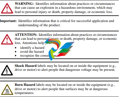
Throughout this manual, when necessary we use notes to make you aware of safety
considerations
Allen-Bradley, Rockwell Automation, and PowerFlex are registered trademarks of Rockwell Automation, Inc. DriveExplorer, DriveExecutive, and SCANport are trademarks of Rockwell Automation, Inc. PLC is a registered trademark of Rockwell Automation, Inc
The information below summarizes the changes to the PowerFlex 40 User Manual since the August 2008 release.
Description of New or Updated Information Page(s)
Minimum Enclosure Volume column and new footnotes added. 1-9, A-2
Drive, Fuse & Circuit Breaker Ratings topic updated. A-1
Electronic Motor Overload Protection description updated. A-4
The information below summarizes the changes to the PowerFlex 40
User Manual since the April 2008 release.
Manual Updates
Description of New or Updated Information Page(s)
Description of A056 revised. 3-17
Description of A059/A062 revised. 3-19
Fault description for F3 revised. 4-3
A table row for electrical specifications added. A-4
Graphic for the “Network Wiring” section revised. C-1
Second last paragraph in the “Network Wiring” section revised. C-2
Text in the “Writing (06) Logic Command Data” section revised. C-4
Frequency source for logic command 001 of bits 14, 13, and 12 corrected. C-4
Text in the “Writing (06) Reference” section revised. C-5
Parameter Updates
The following parameters have been updated with firmware version 6.xx.
Parameter Number Description Page
[Relay Out Sel] A055 Function of option 20, ParamControl,
changed.
Option 24, MsgControl, added.
3-16
[Relay Out Sel] A058, A061 Function of option 20, ParamControl,
changed.
Option 24, MsgControl, added.
3-18
The information below summarizes the changes to the PowerFlex 40
User Manual since the January 2007 release.
Manual Updates
Description of New or Updated Information Page(s)
Input description and attention text for Multiple Digital Input Connection
example corrected.
1-22
New method of changing speed reference for IP66, NEMA/UL Type 4X rated
drives described.
2-2
Description for Up Arrow and Down Arrow keys revised. 2-4
Fault description for F3 revised. 4-3
Graphic for the “Network Wiring” section revised. C-1
Descriptions for bits 6, 7, and 15 of register address 8192 (Logic Command)
updated.
C-4
New information on reading register address 8192 added. C-4
New information on reading register address 8193 added. C-5
Graphic for the “Connecting an RS-485 Network” section corrected. D-4
New method for inverting sign of PID error added.
New Parameter
The following parameter has been added with firmware version 5.xx.
Parameter Updates
The following parameters have been updated with firmware version 5.xx.
Description of New or Updated Information Page(s)
Input description and attention text for Multiple Digital Input Connection
example corrected.


.png)


