
A-BAdjustable Frequency AC Drive
Ungrounded Distribution Systems
ATTENTION: PowerFlex 40 drives contain protective MOVs that are
referenced to ground. These devices must be disconnected if the drive is
installed on an ungrounded or resistive grounded distribution system.
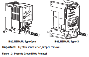
Disconnecting MOVs
To prevent drive damage, the MOVs connected to ground shall be
disconnected if the drive is installed on an ungrounded distribution
system where the line-to-ground voltages on any phase could exceed
125% of the nominal line-to-line voltage. To disconnect these devices,
remove the jumper shown in the Figures 1.1 and 1.2.
1. Turn the screw counterclockwise to loosen.
2. Pull the jumper completely out of the drive chassis.
3. Tighten the screw to keep it in place.
Figure 1.1 Jumper Location (Typical)
Solid state equipment has operational characteristics differing from those of
electromechanical equipment. Safety Guidelines for the Application, Installation
and Maintenance of Solid State Controls (Publication SGI-1.1 available from your
local Rockwell Automation sales office or online at http://
www.rockwellautomation.com/literature) describes some important differences
between solid state equipment and hard-wired electromechanical devices. Because
of this difference, and also because of the wide variety of uses for solid state
equipment, all persons responsible for applying this equipment must satisfy
themselves that each intended application of this equipment is acceptable.
In no event will Rockwell Automation, Inc. be responsible or liable for indirect or
consequential damages resulting from the use or application of this equipment.
The examples and diagrams in this manual are included solely for illustrative
purposes. Because of the many variables and requirements associated with any
particular installation, Rockwell Automation, Inc. cannot assume responsibility or
liability for actual use based on the examples and diagrams.
No patent liability is assumed by Rockwell Automation, Inc. with respect to use of
information, circuits, equipment, or software described in this manual.
Reproduction of the contents of this manual, in whole or in part, without written
permission of Rockwell Automation, Inc. is prohibited.
Throughout this manual, when necessary we use notes to make you aware of safety
considerations

Allen-Bradley, Rockwell Automation, and PowerFlex are registered trademarks of Rockwell Automation, Inc. DriveExplorer, DriveExecutive, and SCANport are trademarks of Rockwell Automation, Inc. PLC is a registered trademark of Rockwell Automation, Inc
The information below summarizes the changes to the PowerFlex 40 User Manual since the August 2008 release.
Description of New or Updated Information Page(s)
Minimum Enclosure Volume column and new footnotes added. 1-9, A-2
Drive, Fuse & Circuit Breaker Ratings topic updated. A-1
Electronic Motor Overload Protection description updated. A-4
The information below summarizes the changes to the PowerFlex 40
User Manual since the April 2008 release.
Manual Updates
Description of New or Updated Information Page(s)
Description of A056 revised. 3-17
Description of A059/A062 revised. 3-19
Fault description for F3 revised. 4-3
A table row for electrical specifications added. A-4
Graphic for the “Network Wiring” section revised. C-1
Second last paragraph in the “Network Wiring” section revised. C-2
Text in the “Writing (06) Logic Command Data” section revised. C-4
Frequency source for logic command 001 of bits 14, 13, and 12 corrected. C-4
Text in the “Writing (06) Reference” section revised. C-5
Parameter Updates
The following parameters have been updated with firmware version 6.xx.
Parameter Number Description Page
[Relay Out Sel] A055 Function of option 20, ParamControl,
changed.
Option 24, MsgControl, added.
3-16
[Relay Out Sel] A058, A061 Function of option 20, ParamControl,
changed.
Option 24, MsgControl, added.
3-18
The information below summarizes the changes to the PowerFlex 40
User Manual since the January 2007 release.
Manual Updates
Description of New or Updated Information Page(s)
Input description and attention text for Multiple Digital Input Connection
example corrected.
1-22
New method of changing speed reference for IP66, NEMA/UL Type 4X rated
drives described.
2-2
Description for Up Arrow and Down Arrow keys revised. 2-4
Fault description for F3 revised. 4-3
Graphic for the “Network Wiring” section revised. C-1
Descriptions for bits 6, 7, and 15 of register address 8192 (Logic Command)
updated.
C-4
New information on reading register address 8192 added. C-4
New information on reading register address 8193 added. C-5
Graphic for the “Connecting an RS-485 Network” section corrected. D-4
New method for inverting sign of PID error added.
New Parameter
The following parameter has been added with firmware version 5.xx.
Parameter Updates
The following parameters have been updated with firmware version 5.xx.
Description of New or Updated Information Page(s)
Input description and attention text for Multiple Digital Input Connection
example corrected.
1-22
New method of changing speed reference for IP66, NEMA/UL Type 4X rated
drives described.
2-2
Description for Up Arrow and Down Arrow keys revised. 2-4
Fault description for F3 revised. 4-3
Graphic for the “Network Wiring” section revised. C-1
Descriptions for bits 6, 7, and 15 of register address 8192 (Logic Command)
updated.
C-4
New information on reading register address 8192 added. C-4
New information on reading register address 8193 added. C-5
Graphic for the “Connecting an RS-485 Network” section corrected. D-4
New method for inverting sign of PID error added. F-6
Parameter Number Description Page
[PID Invert Error] A167 New 3-44
Parameter Number Description Page
[Control Source] d012 Options 7 and 8 added. 3-5
[Start Source] P036 Description revised for option 6. 3-10
[Relay Out Sel] A055 Description revised for option 20. 3-16
[Relay Out Level] A056 Description revised. 3-17
[Opto Outx Sel] A058, A061 Description revised for option 20. 3-18
[Opto Outx Level] A059, A062 Description revised. 3-19
[Internal Freq] A069 Default value for IP66, NEMA/
UL Type 4X drives is 0.0 Hz.
Default value for IP20 rated drives is
60.0 Hz.
3-22
[PID Trim Hi] A130 Description revised. 3-38
[PID Trim Lo] A131 Description revised. 3-38
ATTENTION: The drive contains high voltage capacitors which take
time to discharge after removal of mains supply. Before working on
drive, ensure isolation of mains supply from line inputs [R, S, T (L1,
L2, L3)]. Wait three minutes for capacitors to discharge to safe voltage
levels. Failure to do so may result in personal injury or death.
Darkened display LEDs is not an indication that capacitors have
discharged to safe voltage levels.
!
ATTENTION: Only qualified personnel familiar with adjustable
frequency AC drives and associated machinery should plan or
implement the installation, start-up and subsequent maintenance of the
system. Failure to comply may result in personal injury and/or
equipment damage.
!
ATTENTION: This drive contains ESD (Electrostatic Discharge)
sensitive parts and assemblies. Static control precautions are required
when installing, testing, servicing or repairing this assembly.
Component damage may result if ESD control procedures are not
followed. If you are not familiar with static control procedures,
reference A-B publication 8000-4.5.2, “Guarding Against Electrostatic
Damage” or any other applicable ESD protection handbook.
!
ATTENTION: An incorrectly applied or installed drive can result in
component damage or a reduction in product life. Wiring or application
errors, such as, undersizing the motor, incorrect or inadequate AC
supply, or excessive ambient temperatures may result in malfunction of
the system.
!
ATTENTION: The bus regulator function is extremely useful for
preventing nuisance overvoltage faults resulting from aggressive
decelerations, overhauling loads, and eccentric loads. However, it can
also cause either of the following two conditions to occur.
1. Fast positive changes in input voltage or imbalanced input voltages
can cause uncommanded positive speed changes;
2. Actual deceleration times can be longer than commanded
deceleration times
However, a “Stall Fault” is generated if the drive remains in this state
for 1 minute. If this condition is unacceptable, the bus regulator must be
disabled (see parameter A117). In addition, installing a properly sized
dynamic brake resistor will provide equal or better performance in most
cases.
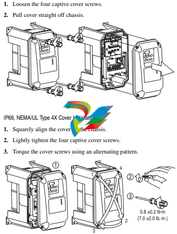
ATTENTION: To avoid an electric shock hazard, ensure isolation of
mains supply from line inputs [R, S, T (L1, L2, L3)] and wait three
minutes for capacitors to discharge before removing the external cover.
Once the cover is removed, verify that the voltage on the bus capacitors
has discharged before performing any work on the drive. Measure the
DC bus voltage at the DC– and DC+ terminals on the Power Terminal
Block (refer to page 1-13 for Power Terminal descriptions). The voltage
must be zero
Mounting Considerations
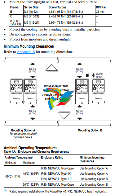
Debris Protection
A plastic top panel is included with the drive. Install the panel to prevent
debris from falling through the vents of the drive housing during
installation. Remove the panel for IP20, NEMA/UL Type Open
applications.
Storage
• Store within an ambient temperature range of -40° to +85°C.
• Store within a relative humidity range of 0% to 95%,
non-condensing.
• Do not expose to a corrosive atmosphere.
AC Supply Source Considerations
General Grounding Requirements
The drive Safety Ground - (PE) must be connected to system
ground. Ground impedance must conform to the requirements of
national and local industrial safety regulations and/or electrical codes.
The integrity of all ground connections should be periodically checked.
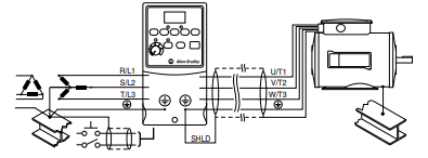
Figure 1.3 Typical Grounding
Ground Fault Monitoring
If a system ground fault monitor (RCD) is to be used, only Type B
(adjustable) devices should be used to avoid nuisance tripping.
Safety Ground - (PE)
This is the safety ground for the drive that is required by code. One of
these points must be connected to adjacent building steel (girder, joist), a
floor ground rod or bus bar. Grounding points must comply with national
and local industrial safety regulations and/or electrical codes.
Motor Ground
The motor ground must be connected to one of the ground terminals on
the drive.
Shield Termination - SHLD
Either of the safety ground terminals located on the power terminal
block provides a grounding point for the motor cable shield. The motor
cable shield connected to one of these terminals (drive end) should also
be connected to the motor frame (motor end). Use a shield terminating or
EMI clamp to connect the shield to the safety ground terminal. The
conduit box option may be used with a cable clamp for a grounding point
for the cable shield.
When shielded cable is used for control and signal wiring, the shield
should be grounded at the source end only, not at the drive end.
RFI Filter Grounding
Using single phase drives with integral filter, or an external filter with
any drive rating, may result in relatively high ground leakage currents.
Therefore, the filter must only be used in installations with grounded
AC supply systems and be permanently installed and solidly
grounded (bonded) to the building power distribution ground. Ensure
that the incoming supply neutral is solidly connected (bonded) to the
same building power distribution ground. Grounding must not rely on
flexible cables and should not include any form of plug or socket that
would permit inadvertent disconnection. Some local codes may require
redundant ground connections. The integrity of all connections should be
periodically checked
Fuses and Circuit Breakers
The PowerFlex 40 does not provide branch short circuit protection. This
product should be installed with either input fuses or an input circuit
breaker. National and local industrial safety regulations and/or electrical
codes may determine additional requirements for these installations.
Fusing
The PowerFlex 40 has been UL tested and approved for use with input
fuses. The ratings in the table that follows are the minimum
recommended values for use with each drive rating. The devices listed in
this table are provided to serve as a guide.
Bulletin 140M (Self-Protected Combination Controller)/UL489
Circuit Breakers
When using Bulletin 140M or UL489 rated circuit breakers, the
guidelines listed below must be followed in order to meet the NEC
requirements for branch circuit protection.
• Bulletin 140M can be used in single and group motor applications.
• Bulletin 140M can be used up stream from the drive without the
need for fuses.
Fuses and Circuit Breakers
!
ATTENTION: To guard against personal injury and/or equipment
damage caused by improper fusing or circuit breaker selection, use only
the recommended line fuses/circuit breakers specified in this section.
Power Wiring
!
ATTENTION: National Codes and standards (NEC, VDE, BSI, etc.)
and local codes outline provisions for safely installing electrical
equipment. Installation must comply with specifications regarding wire
types, conductor sizes, branch circuit protection and disconnect
devices. Failure to do so may result in personal injury and/or equipment
damage.
!
ATTENTION: To avoid a possible shock hazard caused by induced
voltages, unused wires in the conduit must be grounded at both ends.
For the same reason, if a drive sharing a conduit is being serviced or
installed, all drives using this conduit should be disabled. This will help
minimize the possible shock hazard from “cross coupled” power leads.
Motor Cable Types Acceptable for 200-600 Volt Installations
A variety of cable types are acceptable for drive installations. For many
installations, unshielded cable is adequate, provided it can be separated
from sensitive circuits. As an approximate guide, allow a spacing of 0.3
meters (1 foot) for every 10 meters (32.8 feet) of length. In all cases,
long parallel runs must be avoided. Do not use cable with an insulation
thickness less than 15 mils (0.4 mm/0.015 in.). Do not route more than
three sets of motor leads in a single conduit to minimize “cross talk”. If
more than three drive/motor connections per conduit are required,
shielded cable must be used.
UL installations in 50°C ambient must use 600V, 75°C or 90°C wire.
UL installations in 40°C ambient should use 600V, 75°C or 90°C wire.
Use copper wire only. Wire gauge requirements and recommendations
are based on 75 degree C. Do not reduce wire gauge when using higher
temperature wire.
Unshielded
THHN, THWN or similar wire is acceptable for drive installation in dry
environments provided adequate free air space and/or conduit fill rates
limits are provided. Do not use THHN or similarly coated wire in wet
areas. Any wire chosen must have a minimum insulation thickness of 15
mils and should not have large variations in insulation concentricity.
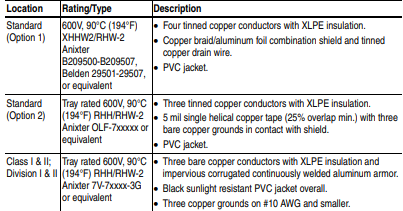
Shielded/Armored Cable
Shielded cable contains all of the general benefits of multi-conductor
cable with the added benefit of a copper braided shield that can contain
much of the noise generated by a typical AC Drive. Strong consideration
for shielded cable should be given in installations with sensitive
equipment such as weigh scales, capacitive proximity switches and other
devices that may be affected by electrical noise in the distribution
system. Applications with large numbers of drives in a similar location,
imposed EMC regulations or a high degree of communications /
networking are also good candidates for shielded cable.
Shielded cable may also help reduce shaft voltage and induced bearing
currents for some applications. In addition, the increased impedance of
shielded cable may help extend the distance that the motor can be
located from the drive without the addition of motor protective devices
such as terminator networks. Refer to Reflected Wave in “Wiring and
Grounding Guidelines for PWM AC Drives,” publication
DRIVES-IN001A-EN-P.
Consideration should be given to all of the general specifications
dictated by the environment of the installation, including temperature,
flexibility, moisture characteristics and chemical resistance. In addition,
a braided shield should be included and be specified by the cable
manufacturer as having coverage of at least 75%. An additional foil
shield can greatly improve noise containment.
A good example of recommended cable is Belden® 295xx (xx
determines gauge). This cable has four (4) XLPE insulated conductors
with a 100% coverage foil and an 85% coverage copper braided shield
(with drain wire) surrounded by a PVC jacket.
Other types of shielded cable are available, but the selection of these
types may limit the allowable cable length. Particularly, some of the
newer cables twist 4 conductors of THHN wire and wrap them tightly
with a foil shield. This construction can greatly increase the cable
charging current required and reduce the overall drive performance.
Unless specified in the individual distance tables as tested with the drive,
these cables are not recommended and their performance against the lead
length limits supplied is not known.
-
 AMAT 0100-00046 AC Current Sense PWB
 -
 AMAT A0414720 Precision Advanced System Controller
 -
 AMAT 0010-00017 Precision Semiconductor Process Interface
 -
 AMAT 01-82889-00 High-Performance Semiconductor Component
 -
 ABB Sample Gas Cooler SCC-C 23070-0-10232110
 -
 IBA ibaRackline-PCHD Efficient process analysis with ibaHD-Server
 -
IBA ibaRackline-PC CAM Frame-accurate video information with ibaCapture
-
IBA ibaRackline-PC Highly available and reliable
-
 IBA Optical Signal Multiplier ibaBM-FOX-i-3o-D
 -
 IBA Optical Data Distribution System ibaBM-DIS-i-8o
 -
IBA Optical Data Concentrator ibaBM-COL-8i-o
-
 IBA ibaNet750-BM-D Acquisition via FO
 -
 IBA ibaW-750 Acquisition via Ethernet
 -
 IBA ibaPADU-8AI-I Compact Measurement Modules
 -
 IBA ibaPADU-D-8AI-I Compact Measurement Modules
 -
 IBA ibaPADU-8AI-U Compact Measurement Modules
 -
 IBA ibaPADU-D-8AI-U Compact Measurement Modules
 -
 IBA ibaPADU-4-AI-U Compact Measurement Modules
 -
 IBA ibaPADU-C-8AI Self-Supplied Data Logger
 -
 IBA ibaBM-ENetIP Bus monitor for EtherNet/IP
 -
 IBA ibaBM-eCAT Bus monitor for EtherCAT
 -
 IBA ibaBM-DP Bus monitor for PROFIBUS
 -
 IBA ibaBM-PN: Bus monitor for PROFINET IO
 -
 IBA ibaMS3xAI-1A Precision AC Current Measurement Module
 -
 IBA ibaDAQ Intelligent Central Unit
 -
 IBA ibaPQU-S Power Quality Monitoring System
 -
 IBA ibaCMU-S Condition Monitoring Unit (CMU)
 -
 IBA ibaPADU-S-IT-2x16 Modular data acquisition and control system
 -
IBA ibaPADU-S-CM Modular data acquisition system
-
 IBA ibaM-4AI-IEPE Input module
 -
IBA ibaM-4AI-UI Input module
-
IBA ibaM-4AI-150V-AC Input module
-
 IBA ibaM-4AI-600V-AC Input module
 -
 IBA ibaLink-SM-256V: High-Density PLC Data Interface
 -
 IBA ibaLink-SM-64V High-Performance S5/S7 Interface
 -
IBA ibaLink-SM-128V-i-2o Synchronous Fiber Optic (ibaNet)
-
 IBA ibaLink-SM-128V communication module
 -
IBA ibaM-4AI-5A-150A-AC Input module
-
 IBA ibaM-FO-2IO Interface module
 -
 IBA ibaM-COM Communication module
 -
 IBA ibaM-DAQ Intelligent Processor Module
 -
 B&R ECE161-0 MULTI digital input module
 -
 B&R ECCP70-01 MULTI CPU type B 42 KByte SRAM
 -
 B&R ECCP60-01 MULTI CPU type B 42 KByte SRAM
 -
 B&R DI426 digital input module
 -
 B&R 2DS100.60-1 electronic drum sequencer Absolut encoder
 -
 B&R 2CP100.60-1 CPU MODULE
 -
 B&R 2BM100.9 High-performance I/O module
 -
 AMAT 0190-14928 SCR Power Controller (PVD Reverse Zone)
 -
 AMAT 0500-01065 300mm Loadlock Interface Interlock Board
 -
 AMAT 2000-21123 Advanced Vacuum Seal Assembly
 -
 AMAT 0660-00090 High-Performance Industrial Power Filter
 -
 AMAT 0240-34077 Centura Endpoint Controller Kit
 -
 AMAT 0195-10215 High-Precision Pedestal Assembly
 -
 AMAT 0190-76050 VGA Video Controller VME Module
 -
 AMAT 0190-75084 High-Performance Communication & Logic Controller
 -
 AMAT 0190-60287 Precision VME/cPCI Interface Control Module
 -
 AMAT 0190-53752 DI Water I/O Controller PCB
 -
 AMAT 0190-37993 DeviceNet Scanner Pro (3U CompactPCI)
 -
 AMAT 0190-37833 MKS CDN500R-5 EPI 300mm Interface Module
 -
AMAT 0190-37771 MKS CDN500R Interlock Control Module
-
 AMAT 0190-37616 High-Precision Analog Input/Output Interface
 -
 AMAT 0190-36787B ISAC CP I/O Block 2 (Top) - Revision B
 -
 AMAT 0190-36787 ISAC CP I/O Block 2 (Top)
 -
AMAT 0190-36511 DIP294 DeviceNet I/O Control Block
-
 AMAT 0190-35764 & 0190-35765: Precision Control Interface Duo
 -
 AMAT 0190-35763 High-Performance Integrated Power Module
 -
 Applied Materials (AMAT) 0190-34512 4-Channel DeviceNet Scanner Interface
 -
 Applied Materials (AMAT) 0190-34282 High-Stability Process Control Module
 -
Applied Materials (AMAT) 0190-27707 High-Precision DeviceNet I/O Controller
-
 Applied Materials (AMAT) 0190-27072 High-Performance Semiconductor Interface
 -
 AMAT 0190-24007 CPCI-3720CF Single Board Computer
 -
 AMAT 0190-23905 Spellman ESC High Voltage Power Supply
 -
 AMAT 0190-22967 High-Density Analog I/O Control Board
 -
 AMAT 0190-22543 High-Precision Analog Input/Output Module
 -
 AMAT 0190-17964 Etch DPS Interlock Module
 -
 AMAT 0190-17894 Interlock Module Conductor HART
 -
 AMAT 0190-17081 2U CompactPCI System Host Processor
 -
 AMAT 0190-16926 and 0190-16928 Based on Compact PCI
 -
AMAT 0190-15915 Intelligent I/O Control Module
-
 AMAT 0190-15840 4-Port UPA DeviceNet Interface Module
 -
 AMAT 0190-15384 Advanced Digital Signal Interface Module
 -
 AMAT 0190-14027 Wafer Flat Finder PCB
 -
 AMAT 0190-12695 SBS CL7 3U CompactPCI Single Board Computer
 -
 AMAT 0190-11817 CP3-SER16-TTL 16-Port Serial Interface Card
 -
 AMAT 0190-11524 CDN500-25 Interlock Module
 -
 AMAT 0190-07450 CompactPCI 48-Channel Digital I/O Interface Board
 -
 AMAT 0190-05990-001 Maglev Rotation System Controller (300mm)
 -
 AMAT 0190-05647 LK3710 Serial Module Transition Card
 -
 AMAT 0190-04457 High-Performance Integrated Circuit Control Module
 -
 Applied Materials (AMAT) 0190-04098 | 5.X Factory Interface I/O Distribution Board
 -
 Applied Materials (AMAT) 0190-03705 | MF Producer SE/E Interlock Module
 -
 Applied Materials (AMAT) 0190-02748 | Flex Scanner Transition Module
 -
 Applied Materials (AMAT) 0190-02362 | Mainframe Interlock 1 Relay Module
 -
 Applied Materials (AMAT) 0190-01227 | Intelligent Motor Control OMS Board
 -
 Applied Materials (AMAT) 0190-00318 | VME 486 Video Controller
 -
 Applied Materials (AMAT) 0130-14007 | Advanced RF Signal Assembly
 -
 Applied Materials (AMAT) 0130-14005 | RF Cable/Interface Assembly
 -
 Applied Materials (AMAT) 0130-01218 | High-Efficiency RF Interface Controller
 -
 Applied Materials (AMAT) 0110-77040 | Head Pneumatic Controller
 -
 Applied Materials (AMAT) 0110-00077 | Precision Control Module
 -
 AMAT 0101-57015 high-performance Next-Generation Deflection Amplifier Board
 -
 AMAT 0100-77040 critical Head Pneumatic Controller Board
 -
 AMAT 0100-76291 Data Buffer / Memory Expansion Interface
 -
 AMAT 0100-76290 Advanced I/O Interface Board
 -
 AMAT 0100-76269 Control Board / Interface Module
 -
 AMAT 0100-71462-01 high-performance Process Controller PCB
 -
 AMAT 0100-71171 Chamber Interlock Control PCB
 -
 AMAT 0100-71154 Semiconductor Circuit Board / Electronic Group Card
 -
 AMAT 0100-70034 PCB Assembly (PCBA) for Endpoint VGA I/O Interconnect.
 -
 AMAT 0100-38032 ESC (Electrostatic Chuck) Controller PCB
 -
 AMAT 0100-36035 DPS Source Match / Seriplex I/O Distribution PCB
 -
 AMAT 0100-35231 Seriplex I/O Distribution Module
 -
 AMAT 0100-35217 TC Amp Interlock PCB Module
 -
 AMAT 0100-35065 High-Precision Serial Isolator PCB
 -
 AMAT 0100-35054 Advanced Chamber Interface Module
 -
 AMAT 0100-20453 DeviceNet Digital I/O Interface Board
 -
 AMAT 0100-20100 High-Performance Semiconductor Component
 -
 AMAT 0100-20068 Precision CCD Image Control Board
 -
 AMAT 0100-20064 Advanced Semiconductor Control Module
 -
Applied Materials (AMAT) 0100-20018 Advanced Communication Interface Module
-
 Applied Materials (AMAT) 0100-20016 High-Performance Interface and Control Module
 -
 Applied Materials (AMAT) 0100-20003 Digital I/O (DI/DO) Interface Board
 -
 Applied Materials (AMAT) 0100-20001 System Electronics Interface (SEI) / PCB Assembly
 -
 Applied Materials (AMAT) 0100-11030 Chamber Hardware / Gas Distribution Component
 -
 Applied Materials (AMAT) 0100-11022 Semiconductor Board Card
 -
 Applied Materials (AMAT) 0100-11018 Advanced Interface Control Module
 -
 Applied Materials (AMAT) 0100-11001 Precision Analog Output Board


