
MOOGMoog GmbH Hydraulic Controls Engineering (HCE) User Manual Control System QAIO 2/2 AV Analog Extension Module with Pulse Input
2 Short Description
2.1 General
The QAIO 2/2 analog module is used for local extension of the inputs and outputs (I/O) of the Moog
Servo Controller (MSC) control module. The analog levels are identical to the levels of the MSC.
The module is mounted on a DIN top-hat rail and directly connected to the MSC via the internal
extension bus (E-Bus).
2.2 Features
Analog I/O extension module with pulse input.
• 2 analog inputs
• 2 analog outputs
• 1 reference voltage output +10 V
• Pulse input
• Connection via E-Bus
2.3 Outputs/Inputs
• 2 analog inputs, each configurable in the MACS development environment as ±10 V,
±10 mA or 4-20 mA. The inputs are converted in multiplex operation.
• 2 analog outputs, each ±10 V, additionally individually configurable in the MACS software
as ±10 mA, ±50 mA or 4–20 mA with wire fault monitoring
• 1 reference voltage output
The reference voltage source provides a short circuit protected voltage of +10 V.
• 1 pulse input 24 V useable as counter input or frequency measurement input
2.4 Module Status LEDs
On the front, 4 LEDs provide information about the status of important module functions.
2.5 Configuration
The configuration of the analog I/O is carried out per software via the central control configuration
in the Moog Axis Control Software (MACS) development environment.
Either the two analog inputs or the pulse input can be used.
2.6 Actuation
The I/O of the analog extension module is actuated directly from the MSC (not D136X001-001 and
D136E001-001) via the extension bus (E-bus). All input- and output-data are transferred within one
cycle of the E-Bus. Therefore the module is perfect for fast control tasks.
2.7 E-Bus
One MSC can be extended with a maximum of 7 QAIO 2/2 modules. It is not possible to combine it
with QAIO 16/4 on one E-Bus segment.
Module data QAIO 2/2-AV I/O extension module
Order number D137-001-011
Connection to M3000 modules Via E-Bus (10 MHz)
Please note:
• It is not possible to connect the module to an MSC
D136X001-001 or D136E001-001
• Combination with QAIO 16/4 V or QAIO 16/4 A on
one E-Bus segment is not possible
• All QAIO 2/2 A/V modules must be connected next to
the E-Bus master MSC. Further E-Bus modules may
be connected right to the QAIO 2/2 A/V modules.
Connection technique Plug-in terminal strips for screwing or clamping
Mounting Mounting rail NS 35/7.5 pursuant to EN 50022 (DIN top-hat
rail)
4 module status LEDs Module functions and diagnosis
Dimensions, WxHxD 124 x 170 x 85.5 (attachment dimension: W = 113/118.5) mm
4.88 x 6.69 x 3.37 (attachment dimension:
W = 4.45/4.67) inch
Temperature range +5°C (+41°F) to +55°C (+131°F) (operation) and
-25°C (-13°F) to +70°C (+158°F) (storage)
Mean temperature in operation for 24 hrs.: max. +50°C
(+122°F)
Relative air humidity 10 % to 95 % (non-condensing)
Operation height Max. 2000 m (6500 ft); storage/transport max. 3000 m
(9800 ft)
Standards
Operating equipment demands and
examinations
IEC 61131-2
Interference emission / immunity EN 61000-6-4 / EN 61000-6-2, industrial part
Shock / vibration IEC 60068 part 2-27 / IEC 60068 part 2-6
Protection class / protection system III / IP20
Insulation strength IEC 61131-2; test voltage 500 V DC
Energy Supply
Voltage supply of module
electronics
+24 V DC (18-32 V DC) SELV pursuant to DIN EN 60950-1
Current consumption of module
electronics
max. 0.25 A
Potential separation Separate potentials for: module electronics, 24 V energy
supply, pulse input
Internal voltages Internally generated via DC/DC converters
Protection against reverse polarity Yes
Analog Inputs
2 analog inputs 16 Bit; individually configurable in the MACS development
environment as ±10 V, ±10 mA or 4–20 mA;
overvoltage protection up to ±36 V
Analog Outputs
2 analog outputs 16 Bit; each ±10 V, additionally individually configurable in
the MACS development environment as ±10 mA, ±50 mA or
4–20 mA
Overvoltage protection up to ±36 V; short-circuit protected
View of the Module and Terminal Assignment
3.1 View of the Module

Analog Outputs
4.1 Basic Wiring Diagram

4.2 Specifications
Number of analog outputs
2
Analog output type
Voltage output ±10 V nominal
Additionally one current output each:
configurable as: ±10 mA, ±50 mA or 4–20 mA (each nominal)
The analog outputs are configured in the PLC configuration of the
MACS development environment.
Output impedance within nominal signal range
<0.2 W (voltage output)
Approx. 1 MW (current outputs)
Digital resolution
16 bit
Data format in the application program
32 bit floating point
Load impedance range
Voltage output ±10 V: ≥ 1.000 Ω
Current output ±10 mA: ≤ 1.000 Ω
Current output ±50 mA: ≤ 200 Ω
Current output 4–20 mA: ≤ 500 Ω
The load impedance range of the current output 4–20 mA does not comply with IEC 61131-2.
(IEC 61131-2 requires a load impedance range of ≤ 600 Ω.)
Update time
The update time corresponds to the task interval of the application program
that actuates the output.
The task interval (and thereby the update time of the outputs) is set in the task configuration of
the MACS development environment.
Rise time T10/90
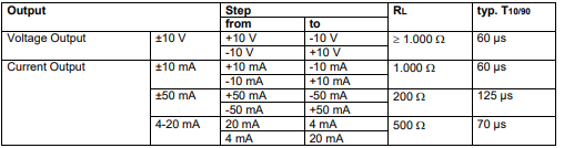
Rise time T10/90 of QAIO 2/2 Analog Outputs Protection Continuous short-circuit protection; overvoltage protection up to ±36 V Short-circuit current IKmax Voltage output ±10 V: IKmax = ±15 mA Current output ±10 mA: IKmax = ±10.92 mA Current output ±50 mA: IKmax = ±54.61 mA Current output 4–20 mA: IKmax = ±20.74 mA
Recommended cable types
Use only shielded cables.
The shield must be made of copper braiding with at least 80% coverage.
The wire must be made of copper with a cross section of at least 0.25 mm2 (23 AWG).
In environments with a high amount of disturbance, use cables with twisted pair wires.
Calibration
The QAIO 2/2 is calibrated at the factory and does not require any additional
calibration.
Permissible load types
Resistive load according to "Load impedance range"
The stability of the current outputs is ensured up to an inductive
load of 100 mH.
The stability of the voltage outputs is ensured up to a capacitive
load of 10 µF.
Output current of the voltage output
Max. 10 mA
Wire fault monitoring of the analog current outputs
The analog current outputs are monitored for wire faults. The status of the wire fault monitoring can
be evaluated in the application program.
4.3 Reference Voltage Output
Reference voltage
+10 V DC
Load current
Max. 5 mA
Precision
±0.3 % of full scale value
Temperature coefficient
< 280 µV/K
Output impedance
< 0.2 Ω
Protection
Continuous short-circuit protection; overvoltage protection up to ±36 V
Short-circuit current
IKmax = 15 mA (residual current of the terminals 91 (REF) and 100
(REF) of the connector X6)
-
 GE IS200AEPBH1B IS200AEPBH1B‑REV‑AA Pitch-Charger Control PCB Board
 -
 GE IS200EDEXG1ADA EX2100 SCR Trigger Control Board
 -
 GE 151X1207CK01SA01 IS200EDEXG1A EX2100 SCR
 -
 GE 151X1233DD02SA02 IS200AEPBH1B - Variant for pitch control charger assembly
 -
 GE 151X1233DB01SA01 IS200AEPBH1B - 10kW Wind Power Converter
 -
 GE 151X1233DB01SA01R | IS200AEPBH1B 10KW Converter
 -
GE 151X1233DD01SA02 Pitch Battery Charger (109W6931P001)
-
GE 151X1233DD01SA02 Pitch Battery Charger Assy IS200AEPBH1B
-
 GE 151X1233DB02SA02 Rev A IS200AEPBH1B Wind Turbine Converter
 -
 GE 151X1207CK02SA02 SCR 4400 V 1850 A IS200EDEXG1ADA General Electric EX2100
 -
 Triconex 3723X 32-Channel TMR Analog Input Module with HART
 -
 SHINKAWA VM-21G SIGNAL CONDITIONER SOCKET
 -
SHINKAWA VM-21R REVOLUTION SIGNAL CONDITIONER
-
SHINKAWA VM-21T DISPLACEMENT INPUT THRUST SIGNAL CONDITIONER
-
SHINKAWA VM-21D 6-WIRE LVDT SIGNAL CONDITIONER
-
 SHINKAWA VM-21P 3-WIRE LVDT SIGNAL CONDITIONER
 -
SHINKAWA VM-21A VIBRATION SIGNAL CONDITIONER
-
SHINKAWA VM-21K DISPLACEMENT INPUT VIBRATION SIGNAL CONDITIONER
-
 SHINKAWA VM-25S01 CONDITION MONITORING SYSTEM
 -
SHINKAWA VM-25 CONDITION MONITORING SYSTEM
-
SHINKAWA VM-772B DEVICE CONFIG
-
SHINKAWA VM-771B MCL VIEW
-
 SHINKAWA VM-76B INSTRUMENT RACK
 -
SHINKAWA VM-75B POWER SUPPLY MODULE
-
 SHINKAWA VM-742B NETWORK COMMUNICATION MODULE
 -
 SHINKAWA VM-741B LOCAL COMMUNICATION & PHASE MARKER MODULE
 -
SHINKAWA VM-722B 9-CHANNEL RELAY MODULE
-
SHINKAWA VM-707B AERODERIVATIVE GAS TURBINE MONITOR MODULE
-
 SHINKAWA VM-706B ROD DROP MONITOR MODULE
 -
 SHINKAWA VM-705B 18-CHANNEL TEMPERATURE MONITOR MODULE
 -
 SHINKAWA VM-704B TEMPERATURE MONITOR MODULE
 -
 SHINKAWA VM-702B ABSOLUTE VIBRATION MONITOR MODULE
 -
SHINKAWA VM-701B VIBRATION / DISPLACEMENT MONITOR MODULE
-
 SHINKAWA MODEL VM-5X INTERFACE UNIT
 -
 SHINKAWA MODEL VM-5W2 DUAL POWER SUPPLY INSTRUMENT RACK
 -
 SHINKAWA MODEL VM-5H4 INSTRUMENT RACK (for VM-5Z5.6.7)
 -
SHINKAWA MODEL VM-5G SINGLE UNIT INSTRUMENT RACK
-
SHINKAWA MODEL VM-5Z5,6,7 POWER SUPPLY UNIT
-
SHINKAWA MODEL VM-5Y1,2,3 RELAY MODULE UNIT
-
 SHINKAWA MODEL VM-5P3 PHASE MARKER UNIT
 -
 SHINKAWA MODEL VM-53 DUAL COMMUNICATION UNIT
 -
 SHINKAWA MODEL VM-52 BOTTOM HOLD MONITOR
 -
SHINKAWA MODEL VM-51 ROD DROP MONITOR
-
SHINKAWA MODEL VM-5R TACHOMETER
-
SHINKAWA MODEL VM-5S DUAL TACHOMETER
-
SHINKAWA MODEL VM-5A DUAL VALVE
-
SHINKAWA MODEL VM-5E DUAL CASE
-
SHINKAWA MODEL VM-5L COMPLEMENTARY INPUT
-
SHINKAWA MODEL VM-5N RAMP DIFFERENTIAL
-
SHINKAWA MODEL VM-5D DUAL DIFFERENTIAL
-
SHINKAWA MODEL VM-5T DUAL THRUST MONITOR
-
SHINKAWA MODEL VM-5C ECCENTRICITY MONITOR
-
SHINKAWA MODEL VM-5M DUAL PATH MONITOR
-
SHINKAWA MODEL VM-5B DUAL ACCELERATION MONITOR
-
SHINKAWA MODEL VM-5U DUAL SEISMIC MONITOR
-
SHINKAWA MODEL VM-55 VIBRATION MONITOR
-
 SHINKAWA VM-742B1-5 VIBRATION MONITORING SYSTEM CARD
 -
 Shinkawa PSP-17B P-24-64A P-24-64B Circuit Board Module
 -
 SHINKAWA MGP-67 PCB
 -
 Shinkawa JBP-278 P-22-48A-1 P-22-48B-1 Circuit Board Module
 -
 Shinkawa VM-721B 18-CHANNEL RELAY MODULE
 -
Shinkawa FRP-337 P-26-54A P-26-54B Circuit Board Module
-
 Shinkawa CPP-111 P-25-59A P-25-59B Circuit Board Module
 -
Shinkawa WKN-142K2-2 Vibration Transmitter
-
 SHINKAWA VL-202A08L-1012 Rotor Position Monitor Probe Sensor
 -
 Shinkawa CPP-128 P-26-74A P-26-74B Circuit Board Module
 -
 Honeywell 51402755-100 PROCESSOR CARD
 -
 Honeywell 51107595-100 Power
 -
HONEYWELL 51304544-100 Control Board
-
 HONEYWELL 51109919-100 BOARD
 -
 HHoneywell 51204160-175 Digital Input Module
 -
 Honeywell 51304754-150 High Level Analog Input Module
 -
 HONEYWELL 51304690-100 DIGITAL INPUT CARD
 -
 Honeywell 51401635-150 COMM CONTROL
 -
 HONEYWELL 51204174-175 MC-TAOY 52 ANALOG OUTPUT BOARD
 -
 HONEYWELL 51400596-100
 -
 HONEYWELL 51401291-100 board card
 -
 HONEYWELL 51401642-150 I/O LINK MODULE
 -
 Honeywell LCN‑E Hub Power Supply 38500148‑300
 -
 Honeywell LCN‑E Hub redundant 38500143‑202 Twisted‑pair LCN
 -
 Honeywell LCN‑E Hub non‑redundant,38500143‑102
 -
Honeywell Enhanced Micro‑TDC‑3000 System Unit MX‑DTAC01K2
-
 Honeywell Enhanced Micro‑TDC‑3000 System Unit MX‑DTAB01K2
 -
 Honeywell Enhanced Micro‑TDC‑3000 System Unit MT11‑520
 -
 Honeywell STI‑CE Smart Transmitter Interface 51304516‑150
 -
 Honeywell STI Smart Transmitter Interface 51304516‑100 MC‑PSTX02
 -
 Honeywell ulse Counter IOP,51304386‑100.MU‑PPIX02
 -
 Honeywell DO Digital Output IOP‑CE 51304487‑150 CE version
 -
.png) Honeywell DO Digital Output IOP 51304487‑100 MC‑PDOX02
Honeywell DO Digital Output IOP 51304487‑100 MC‑PDOX02 -
 Honeywell TDC‑3000 SOE DI IOP,51402625-175 MC‑PDIS12
 -
 Honeywell TDC‑3000 DI Digital Input IOP‑CE 51304485‑150
 -
Honeywell TDC‑3000 DI Digital Input IOP 51304485‑100 MC‑PDIX02
-
Honeywell TDC‑3000 AO Analog Output IOP 51304757‑100 MU‑PAOX02
-
Honeywell TDC‑3000 TC Thermocouple IOP 51304756‑100 MU‑TAMT03
-
 Honeywell TDC‑3000 51304755‑100 MU‑TAMR03
 -
 Honeywell TDC‑3000 LLAI Multiplex AI IOP,51304362‑150
 -
 Honeywell TDC‑3000 HLAI Analog Input IOP‑CE,51304363‑150
 -
 Honeywell TDC‑3000 HLAI Analog Input IOP,51304363‑100.4‑20mA
 -
Honeywell TDC‑3000 HPM Power Supply,51401731‑100
-
 Honeywell TDC‑3000 Standard 1986.HPM High‑Performance PM CPU,51402362‑100
 -
Honeywell TDC‑3000 APM Advanced Process Manager CPU,51304459‑100
-
Honeywell TDC‑3000 Standard 1986.PM Process Manager CPU,51304362‑100
-
Honeywell TDC‑3000 NIM Network Interface Module,51304481‑200
-
 Honeywell TDC‑3000 NIM Network Interface Module 51304481‑100
 -
 Honeywell TDC‑3000 BASIC,LCN Terminator Resistor,30732052‑001.Coaxial
 -
Honeywell TDC‑3000 BASIC,Hiway Coupler,30753732-001
-
 Honeywell TDC‑3000 BASIC,LEPIU Low‑Energy PIU,4DP7APCFA309
 -
Honeywell TDC‑3000 BASIC,HLPIU High‑Level PIU,4DP7APCFA106
-
Honeywell TDC‑3000 BASIC,Multifunction Controller(TDC‑2000 DHW),4DP7MFA103
-
 Honeywell TDC‑3000 BASIC,Extended Controller(TDC‑2000 DHW),4DP7AXA102
 -
Honeywell TDC‑3000 BASIC,Basic Controller(TDC‑2000 DHW),4DP7BBA101
-
Honeywell TDC‑3000 BASIC,XLCNE2 LCN Extender,51305508‑100.Coaxial LCN
-
 Honeywell TDC‑3000 BASIC,E‑PLCG PLC Gateway,51400997‑200
 -
 Honeywell TDC‑3000 BASIC,PLNM Plant Network Module,51401163‑100
 -
 Honeywell TDC‑3000 BASIC,CG Computer Gateway,80360206‑001
 -
 Honeywell TDC‑3000 BASIC,HG High‑Speed Gateway,51304526‑100
 -
 Honeywell TDC‑3000 BASIC,HM History Module,51191596‑200
 -
Honeywell TDC‑3000 BASIC,HM History Module,51191596‑100
-
Honeywell TDC‑3000 BASIC,AM Application Module CPU,51401551‑800.K2LCN‑8
-
Honeywell TDC‑3000 BASIC,AM Application Module CPU,51401551‑600.K2LCN‑6
-
 Honeywell TDC‑3000 BASIC,AM Application Module CPU,51401551‑400,K2LCN‑4
 -
 Honeywell TDC‑3000 BASIC,AM Application Module CPU,51401551‑300.K2LCN‑3
 -
Honeywell TDC‑3000 BASIC,AM Application Module CPU,51401551‑200,K2LCN‑2
-
 Honeywell TDC‑3000 BASIC,US Universal Station CPU,51401288‑200
 -
TDC‑3000 BASIC,US Universal Station CPU,51401288‑100
-
 SHINKAWA VM-21P1 Signal Conditioner 0-50MM 24VDC
 -
 Shinkawa RiverNew Vibration Transducer VK202 Series
 -
 Shinkawa Electric VM-3E2 Vibration Monitor Module


