
EMERSONDeltaV SISTM Logic Solver
World’s first smart SIS Logic Solver
Integrated, yet separate from the control
system
Easy compliance with IEC 61511
Scales to fit any size application
SIL 3-rated
Online addition of Logic Solvers
Introduction
The DeltaV SIS system, part of Emerson’s smart SIS,
ushers in the next generation of Safety Instrumented
Systems (SIS). This smart SIS approach uses the power
of predictive field intelligence to increase the availability of
the entire safety instrumented function.
Benefits
The World’s first smart SIS. Research shows that
over 85% of all faults in SIS applications occur in field
instruments and final control elements. The DeltaV SIS
system has the first smart Logic Solver. It communicates
with intelligent field devices using the HART protocol to
diagnose faults before they cause spurious trips. This
approach increases process availability and reduces
lifecycle costs.
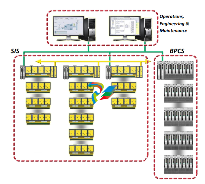
Integrated yet separate. Safety standards insist on
separation of the control and safety systems in order to
remove any possibility of a common failure affecting both
layers of protection. End users require an integrated
configuration, maintenance, and operations environment.
The DeltaV SIS system has a unique solution to this
problem; implementing safety functions with dedicated
hardware, software, and networks while being seamlessly
integrated at the workstations.
Easy Compliance with IEC 61511. IEC 61511
demands rigorous user management and the DeltaV SIS
platform provides it. IEC 61511 requires that any changes
made from an HMI (e.g. to a trip limit) be extensively
vetted to ensure that the right data is written to the right
Logic Solver. The DeltaV SIS system automatically
provides this data verification.
Scales to fit any size application. Whether you have
an isolated wellhead or a large ESD/fire and gas
application, the DeltaV SIS system scales to provide you
with the safety coverage you need for your SIL 1, 2 and 3
safety functions. Each Logic Solver has dual CPUs and
sixteen channels of I/O built into it. This means that no
additional processors will ever be required to expand the
system, since each Logic Solver contains its own CPUs.
Scan rate and memory usage are constant and
independent of system size.
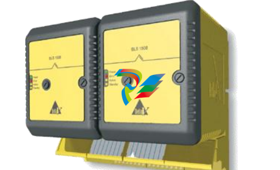
SIL 3-rated. DeltaV SLS 1508 Logic Solvers are installed
in redundant pairs for increased process availability of
your SIS loops.
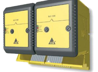
A redundant SLS 1508 Logic Solver
Redundant architecture includes:
dedicated redundancy link
separate power supply to each Logic Solver
I/O published locally every scan on redundant peerto-peer link
same input data for each Logic Solver
Online addition of Logic Solvers. The system
checks for new hardware every scan, so equipment can
be added to an on-line system in real time. Online addition
of new logic solvers means your process does not get
interrupted. As new equipment is added, the DeltaV
Explorer software recognizes it and makes it ready to be
configured.
Product Description
This section provides general information on DeltaV SIS
hardware. Refer to the Installing Your DeltaV Digital
Automation System manual for more information on
DeltaV system equipment.
DeltaV SIS Equipment
A DeltaV automation system consists of carriers, one or
more I/O subsystems, controllers, power supplies,
workstations, and a control network.
The DeltaV SIS system consists of:
Redundant Logic Solvers (SLS 1508) and termination
blocks
SISnet Repeaters (see separate product data sheet)
Carrier extender cables
Local peer bus extender cables
Right 1-wide carrier with termination
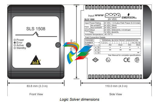
Logic Solvers (SLS1508) contain the logic-solving
capability and provide an interface to 16 I/O channels that
can be configured as Discrete Input, Discrete Output,
Analog Input (HART) and HART two-state output
channels. Logic Solvers and termination blocks install on
the 8-wide carrier. Logic Solvers communicate with each
other through the carriers over a two-channel, local peer
bus (SISnet) and remote peer ring. Local Logic Solvers
are hosted by the same DeltaV controller and remote
Logic Solvers are hosted by a different DeltaV controller.
Logic Solvers are powered by a 24 V DC power supply
that is separate from the power supply that drives the
DeltaV controller and I/O. Logic Solvers install in oddnumbered slots (1,3,5,7) on the 8-wide carrier. Redundant
Logic Solvers use four slots.
SISnet Repeaters extend communication beyond the
local Logic Solvers connected to one DeltaV controller and
broadcast global messages to remote Logic Solvers
through a fiber-optic ring Carrier extender cables extend
Local Bus power and signals between 8-wide carriers.
Local peer bus extender cables extend the local peer bus
(SISnet) between Logic Solvers on different carriers. 1-
wide carriers with terminators terminate the local peer bus
at the final carrier.
Communication
Control Network: The DeltaV Control Network provides
communication between the nodes in the DeltaV network.
Refer to the Installing Your DeltaV Digital Automation
System manual for complete information on the Control
Network.
Local Bus: The Local Bus provides communication
between DeltaV controllers and Logic Solvers and
between DeltaV controllers and SISnet Repeaters.
Local Peer Bus (SISnet): Logic Solvers communicate
with other Logic Solvers and with local SISnet Repeaters
through the carriers over a 2 channel local peer bus. The
same message is broadcast over both channels. The local
peer bus must be terminated at both ends. The local peer
bus is terminated at the left end through the 2-wide
power/controller carrier and at the right end through a
terminated 1-wide carrier.
The SISnet Repeaters can be located anywhere on a local
peer bus – between the DeltaV Controller(s) and the
terminated 1-wide carrier.
Remote Peer Ring: SISnet Repeaters hosted by one
DeltaV controller communicate with SISnet Repeaters
hosted by a different DeltaV controller over a fiber-optic
remote peer ring. A local SISnet Repeater collects locally
generated messages that have been designated as global
variables into a single message and sends it to the next
SISnet Repeater in the ring. Upon receipt of a message,
the receiving SISnet Repeater broadcasts it on its local
peer bus (SISnet) and forwards the message to the next
SISnet Repeater in the ring. A global message is
forwarded around the ring once. The primary SISnet
Repeaters form one fiber-optic ring and the secondary
form a separate, independent ring.
Carrier extender cables and local peer bus extender
cables connecting a DeltaV controller and 8-wide carrier
with standard DeltaV I/O and DeltaV SIS Logic Solvers to
a second 8-wide carrier (hosted by the same controller)
are installed with Logic Solvers, SISnet Repeaters, and a
terminated 1-wide carrier. Logic Solver messages are
communicated to a remote DeltaV SIS (hosted by a
separate controller) through fiber-optic cables.
DeltaV SIS Product Data Sheet
May 2013 – Page 5 DeltaV SIS Logic Solver
Unique Redundancy Methodology
Introduction to Redundancy
Unlike other SIS Logic Solvers, the SLS 1508 is rated
suitable for use in SIL 3 applications in simplex mode.
Redundant SLS 1508 Logic Solvers run in parallel at all
times. Both read the inputs from the I/O terminals, both
execute the logic and both drive the outputs at the I/O
terminals. There is no concept of primary and backup or
master and slave, which is unlike any other SIS. The only
difference between the two is that one communicates with
both the engineering and operator workstations and the
dedicated safety network (SISnet); this is the one with the
Active light on the bezel. The other (Standby) is
communicating only on the SISnet.
In the event that a failure is detected in one of the SLS
1508 Logic Solvers, it automatically goes to a failed state.
In this condition all its output channels are de-energized;
this has no impact on the other Logic Solver or the
physical outputs because the other Logic Solver continues
to read inputs, execute logic and drive outputs. The
transition from redundant to simplex mode is therefore
completely bumpless.
Redundancy
The redundant SLS 1508 Logic Solver modules are
connected to the field at the redundant terminal block. No
control strategy configuration is required to take
advantage of SLS 1508 Logic Solver redundancy, as the
system’s auto-sense capability automatically recognizes
the redundant pair of Logic Solvers.
An integrity error alarm in a redundant Logic Solver pair
will notify the operator of a failure. Both Logic Solvers in a
redundant pair are monitored for integrity alarms at all
times.
Events that can cause integrity alarms include:
Hardware failure within a Logic Solver
Communications failure between a Logic Solver and
the SISnet
Communications failure between a redundant pair of
Logic Solvers
Communications failure between a Logic Solver and
an DeltaV Controller
Removal of a Logic Solver from the carrier
The health and status of both Logic Solvers and their
channels are available in the diagnostics explorer.
When one of a redundant pair of SLS 1508 Logic Solvers
is removed online there is no disturbance to the process.
When the missing Logic Solver is replaced with another
Logic Solver, the new Logic Solver completes its power-up
self-tests before the active Logic Solver cross-loads the
current database. In safe areas, failed Logic Solvers can
be replaced under power. In hazardous areas, appropriate
installation procedures must be followed.
Automatic proof testing can be selected on a redundant
pair of Logic Solvers. The desired proof-test interval is set
in the configuration and the Logic Solvers perform the
proof test automatically. A warning is given to the operator
before the automatic proof test is started.
Sequence of Events Capability
With DeltaV SIS, events are automatically generated as
function blocks are executed within a module scan. Events
are time stamped with a resolution of <1 ms, and they are
recorded in the sequence that they occur in the Event
Chronicle. When using standard function blocks such as
input blocks, voter blocks, and cause and effect blocks, a
standard set of events are automatically generated without
special configuration or programing required. For example,
I/O failures, trip limits, first outs, and other similar events
are automatically time stamped by function blocks and
recorded in the Event Chronicle. When a process variable
exceeds the trip limit, DeltaV SIS records the event along
with the analog value and the trip condition.
In general, when there is a plant event that triggers an
emergency shutdown from the SIS, one input will exceed
a trip limit on one scan and this will cause outputs to trip
and more inputs will then change state. Sequence of
Events Recording has been used to find that first input that
caused the trip by looking at all of the inputs in the plant.
With the DeltaV SIS system, the operator simply filters the
Event Chronicle for first out trips, and the first-out is clearly
visible.
If higher resolution is required for some channels then
they can be wired to both the DeltaV SIS Logic Solver and
also to a DeltaV Discrete Input Card for Sequence of
Events, which provides a resolution of 0.25 ms.
DeltaV SIS Product Data Sheet
May 2013 – Page 6 DeltaV SIS Logic Solver
System Compatibility
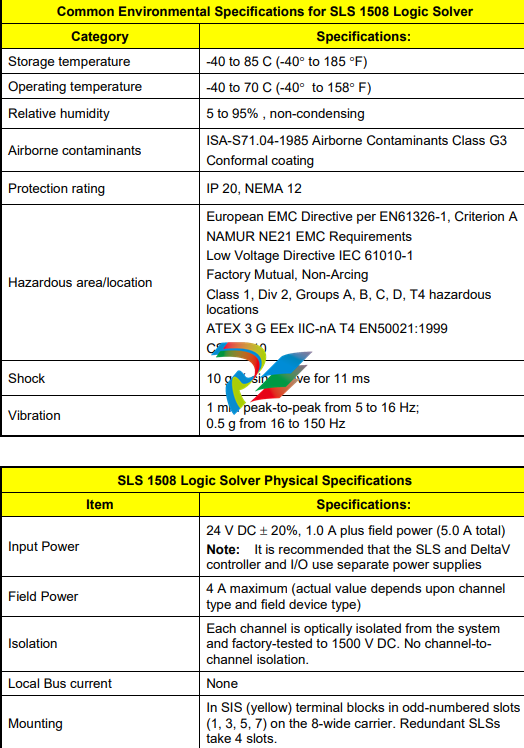
DeltaV SLS 1508 Specifications
SLS 1508 Logic Solver Weight, Heat Generation and Power Consumption
Item Specifications:
Redundant Logic Solver
Weight – 1.20 kg
Heat Dissipation – 24 W
Power – 2 A @ 24 V DC + Dig out Field Loads
DeltaV SIS Product Data Sheet
May 2013 – Page 8 DeltaV SIS Logic Solver
Channel Specifications
The Logic Solver provides 16 channels of flexible I/O, meaning that each channel can be configured as an Analog Input
(HART), HART Two-State Output, Discrete Input, or Discrete Output channel.
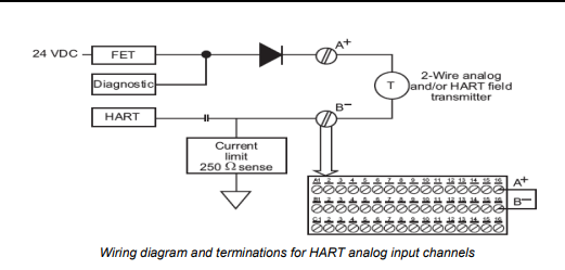
Analog Input Channel Specifications (includes HART)
Item Specifications:
Number of channels 16
Isolation
Each channel is optically isolated from the system
and factory-tested to 1500 V DC. No channel-tochannel isolation.
Nominal signal span 4 to 20 mA
Full signal range 1 to 24 mA
2-wire transmitter power 15.0 V minimum terminal-to-terminal @ 20 mA;
current limited to 24 mA max
Safety / diagnostic accuracy 2.0% of span
Resolution 16 bits
Filtering
2-pole, corner frequency 5.68 Hz
-3 dB at 5.68 Hz
-20.0 dB at 40 Hz (half the sample rate)
-
 Hirschmann RS20-1600M2T1SDAEHH03.1.02 Rail Switch
 -
 Hirschmann BRS30-24TX Industrial Rail Switch
 -
 Hirschmann RSPM20-4T14T1EV9HHS999.9.99 Managed Ethernet Switch
 -
 Hirschmann BELDEN RS40-0009CCCCSDAPHH09.0.14 / RS400009CCCCSDAPHH09014
 -
Hirschmann RS40 Rail Switch RS40-0009CCCCSDAE
-
 Hirschmann BELDEN RS30-0802T1T1SDAP / RS300802T1T1SDAP Fully Managed Layer 2 Compact Rail Switch
 -
 Hirschmann BELDEN RS20-0800M2M2SDAUHH / RS200800M2M2SDAUHH
 -
 Hirschmann EAGLE30-04022O6TT999SCCY9HSE3F Industrial Firewall Router Switch
 -
 Hirschmann RS20-1600T1T1SDAEHH09.0.14 RS20 Rail Mount Ethernet Switch
 -
 Hirschmann EAGLE0200T1T1TDDY90000HHE05.3.03 Industrial Security Router
 -
Hirschmann - BELDEN MIPP-AD-1L9P
-
 HIRSCHMANN RSPM20-4Z64Z6TV9HHS9 942 106-999 RAIL SAFETY SWITCH
 -
 HIRSCHMANN FIBEROPTIC MODULE FIP P/N: OZDFIPG3T
 -
 HIRSCHMANN RS20-1600M2M2SDAUHH Ethernet rack-mounted switch
 -
 HIRSCHMANN BELDEN RS20-0400T1T1SDAEHH04.0.01 / RS200400T1T1SDAEHH04001
 -
HIRSCHMANN MM2-4FXM3 MICE Media Module
-
HIRSCHMANN RS20-0800M2M2SDAE Industrial Ethernet Rail Switch
-
 Hirschmann RS20-2400T1T1SDAP / RS20-2400T1T1SDAPHH05.0.02
 -
 GE MLJ1005B010H00C MLJ Digital Synchromism Check
 -
 ALSTOM MICROTECH DX21-M2 Digital Excitation Controller
 -
HIRSCHMANN BRS20-1200ZZZZ-STCY99HHSES
-
 HIRSCHMANN MM3-4FXM2 MICE Media Module
 -
Hirschmann RSB20-0800T1T1SAABHH 8Port ENet Rail Switch RSB20
-
 Hirschmann MACH102-8TP Ethernet Switch
 -
 SAACKE DDZ-M marine steam pressure atomizer
 -
 SAACKE SKV-A marine rotary cup atomizer
 -
 SAACKE Seavis HMI05e
 -
 Kollmorgen MMC-SD-2.0-230 Servo Drive 100-240VAC 2KW 10A Output 3PH 100-240VAC
 -
 Kollmorgen Servo drive CR10550
 -
 Kollmorgen AKD-P01207-NACN-0054 Servo Driver
 -
 Kollmorgen S406M-CA-036 Servostar
 -
.png) Kollmorgen AKD-B02407-NAAN-0000 Digital Servo Drive
Kollmorgen AKD-B02407-NAAN-0000 Digital Servo Drive -
 Kollmorgen SERVOSTAR S406AM-CA Digital Servo Drive
 -
 KOLLMORGEN SERVOSTAR 603-AS SERVO AMPLIFIER_SERVOSTAR603AS_S60301
 -
Kollmorgen S700 Servo Controller (S70602-NANANA-NA)
-
 Kollmorgen MPK411 controller
 -
 KOLLMORGEN MMC-SD-1.3-460-D Smart Drive
 -
 KOLLMORGEN AKM21C-CKB2AA-00 / AKM21CCKB2AA00 Servomotor
 -
 BECKHOFF AX5106-0000-0200 | Digital Compact Servo Drives 1-channel
 -
 BECKHOFF C3620-0000 INDUSTRIAL COMPUTER (MOTORSHELVES)
 -
 Beckhoff EK1960-0000 TwinSAFE Compact Controller
 -
 Beckhoff C6930-0050 Control Cabinet Industrial PC
 -
 Beckhoff CP7711-0001-0030 Industrial Computer Detection
 -
 Beckhoff CX1001-0111 Embedded PC CPU Module
 -
 Beckhoff C6017-0020 | Ultra-compact Industrial PC
 -
 Beckhoff EK1322 | 2-port EtherCAT P junction with feed-in
 -
 Beckhoff CP2219-0010 Panel
 -
 BECKHOFF C6015-0020 ULTRA COMPACT INDUSTRIAL PC
 -
 BECKHOFF CX2030-0120/Standard CPU Module Embedded PC Windows PLC controller
 -
 Beckhoff CP7721-1090-0020 Panel PC
 -
 Beckhoff PC CPU Module CX5130-0175
 -
 Beckhoff C6920-0050 Control Cabinet
 -
 Beckhoff EL6631 EtherCAT 2-Port Communication Interface, Profinet RT Controller
 -
 Beckhoff CP6202-0001-0060 touch screen panel PC
 -
 Beckhoff CP3916-1002-0000 Multi-Touch Control Panel
 -
 Beckhoff EP1809-0021 | EtherCAT Box, 16-channel digital input, 24 V DC, 3 ms, M8Preferred type
 -
 Beckhoff CX8190 PLC Embedded Industrial PC Ethernet Controller
 -
 Beckhoff CX2100-0914 Power Supply for External
 -
 Beckhoff Automation CP6906-0001-0000 HMI
 -
 Beckhoff EP7342-0002 Module
 -
 Beckhoff CX1020-0112 / CX1100-0910 / CX1020-N010 / CX1100-0003 Windows CPU
 -
 Beckhoff EP7211-0034 EtherCAT Box 1 Channel Motion Interface
 -
 Beckhoff C6240-0030 Control cabinet Industrial PC
 -
 beckhoff motherboard CB1052-0004 CB1052-0004
 -
 Beckhoff AX2006-AS Servo Drive / Variable Frequency Drive
 -
BECKHOFF CP6207-0001-0020 NSMP
-
 Beckhoff C6930-1142-0060 Industrial Computer
 -
 Beckhoff FC7501-0000 interface card
 -
 Beckhoff CX5140-0175 Embedded PC PLC CPU CX5140 Industrial Controller
 -
 Beckhoff CP7802-1100-0010: High-End IP65 Control Panel with DVI/USB Extended Interface
 -
BECKHOFF CP3716-1058-0010 CONTROL PANEL
-
 Beckhoff AX8108-0000 Single-Axis Module
 -
 Beckhoff CU8851-0000 | USB extension, USB Extended 2.0 receiver box
 -
Beckhoff C6017-0030 | Ultra-compact Industrial PC
-
 Beckhoff CX1001-0120/CX10010120.cx1000-n001.cx1000-n000 System Overview
 -
 Beckhoff CPU Module CX5140-0155/4GB CPU Module
 -
 Beckhoff CP6533-0001-005: Built-in Panel PC with High-Definition Multi-Touch Control
 -
 Beckhoff EL5042 | EtherCAT Terminal, 2-channel encoder interface, BiSS® C
 -
 Beckhoff C6920-1080-0040: Premium Control Cabinet Industrial PC
 -
 Beckhoff C6920-0060 | Control cabinet Industrial PC
 -
 Beckhoff Embedded-PC CX5010-1121
 -
 Beckhoff CB3050-0010 Mainboard Motherboard
 -
 Beckhoff PLC module CX1020-0000 Basic CPU module (service phase)
 -
 Beckhoff CP7812-1056-0010 15" Multitouch Display Control Panel
 -
 Beckhoff CX5120-0115 /2GB Controller Module
 -
 Beckhoff CP7201-1000-0000 Industrial Panel PC
 -
 Beckhoff Servo Motor AM8061-0JH1-0000
 -
 BECKHOFF CP6503-0001-0050 Built-in Panel PC
 -
Beckhoff CP3919-0010 Display G190ETN01.2 19" PCT V04. Multi-touch Control Panel
-
 Beckhoff CX5110-0112-9020/000368201 Embedded PC Intel Atom Processor
 -
 Beckhoff AX8206-0000 Dual-Axis Module
 -
Beckhoff Nail Operating Terminal CP7032-1031-0010
-
Beckhoff AM8042-0EH1-0000 Servomotor 4.10 Nm (M0), F4 (87 mm)
-
 Beckhoff EK9300 Beckhoff CPU Module
 -
Beckhoff CP3224-0020 Multitouch-Panel-PC
-
 Beckhoff CP2712-0000 12.1" 24VDC Touch Screen WMD0
 -
 BECKHOFF CX5240-0195 / 0000289234 Embedded PC 40 GB CFast Card
 -
 Beckhoff CP6932-1000-0000 Control Panel
 -
 BECKHOFF CX5120-0121 PLC Module
 -
 Beckhoff EL3218 | EtherCAT Terminal, 8-channel analog input
 -
Beckhoff C6640-0050 | Control cabinet Industrial PC
-
 Beckhoff Cx5130-0120/4GB Embedded-PC
 -
 BECKHOFF CX2030-0122 PLC PROCESSOR
 -
 BECKHOFF CX5020-0122 Controller Module
 -
 Beckhoff CP3915-0000 Multitouch Panel
 -
 BECKHOFF EL3014 | EtherCAT Terminal
 -
 BECKHOFF Industrial Computer c6920-1057-0030
 -
 Beckhoff CX5130-0141/4GB CX5130-0141 Embedded PC
 -
 Beckhoff C6240-1052-0040 4-086-06-3073 Industrial Computer
 -
 Beckhoff CX5140-0135 /4GB High-Performance Embedded Industrial PC
 -
 Beckhoff C6515-1001-0000 Industrial PC
 -
 Beckhoff AX5103-0000-0200 - Digital Compact Servo Drives
 -
 Beckhoff CX2030-0130-1003/4GB Basic CPU module
 -
 Beckhoff AX8620-0000 Power Supply Module
 -
 Beckhoff CX9020-0111 module with
 -
 Beckhoff EL7332 PLC Module
 -
 BECKHOFF CP7709-0001-0020 HMI
 -
 Beckhoff CX5120-0155/2GB Embedded PC
 -
 BECKHOFF CP7037-1037-0010 OPERATOR INTERFACE TOUCHSCREEN
 -
 Beckhoff EK9000 | ModbusTCP/UDP Bus Coupler
 -
 Beckhoff Touch Panel Screen CP6020 -0000-0000
 -
 Beckhoff CX2020-0121 Module FAST Shipping
 -
 Beckhoff CX2030-0125 Basic CPU Module
 -
 Beckhoff CP3918-0000 Multi-Touch 18.5" Control Panel
 -
 Automotion LC4A00010 DC BL Motor Control, ATS, Sub Assy, SCP, 115VAC,
 -
 500T-115VAC - VAS ENGINEERING - DORIC 500 SERIES DIGITAL TEMP INDICATOR
 -
 Honeywell X-DCS2000/EN Digital Integrated System Manager 50/60Hz 100-240V #4
 -
 Kollmorgen S60600 Servostar600 606-Fan 4 kVA, 6 A, 3 X 230 - 480 V


