
DCS Industrial control system
Product
Article
NameDescriptionContent
NEW CENTER
Current Location:
ABBDevice Management PROFIBUS DP/FMS Redundancy Link Module, RLM01
From:ABB
|
Author:LIAO
|
Time :2025-08-12
|
456 Browse:
|
🔊 Click to read aloud
❚❚
▶
|
Share:
Section 5 Signalling
The monitoring logic in RLM 01 indicates operating and possible error states via LEDs on the front panel. In normal operation, all yellow Act LEDs (flashing or continuous) and the green Pwr LED are lit. The two red Err LEDs are unlit. Any signalling configuration other than this indicates a communication or power supply error
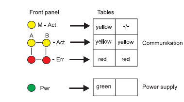
The text (yellow, red, green) in the two following tables means that the corresponding LED is lit, thus displaying an operating or error state
-
 OMRON 3G3XV-A2007 3G3XV-A2007-NEV2
 -
 Omron NJ1019000 NJ1 programable logic controller
 -
 OMRON C120-LK202-EV1/C120LK202EV1
 -
 OMRON C200H-AD003 PLC
 -
 OMRON C200H-CPU23-E COIL 24VDC PLC
 -
 Omron C200HG - C200H-ID212- C200H-OC226 C200HW-BC101 PLC Base Unit
 -
 OMRON C200H-OC222(Output Unit),C200H-PS211(Power Supply Unit),SP001 Module Rack
 -
 OMRON C200H-RT201 PROGRAMMABLE CONTROLLER
 -
 OMRON C200HS-CPU01-E SYSMAC PROGRAMMABLE CONTROLLER
 -
 OMRON C200H-SNT31 C200H Programmable Controllers
 -
 OMRON C200HW-MC402-E Motion control unit
 -
 OMRON C200PC-ISA02-DRM-E PLC ISA bus compatible board card
 -
 OMRON C500-CT012 PLC
 -
 OMRON C500-NC103-E PLC
 -
 OMRON C500-NC222-E PLC
 -
 OMRON C500-PRW05-V1 PLC
 -
 OMRON C500-PRW06 PROGRAMMABLE CONTROLLER
 -
 OMRON C500-PS223-E 3G2A5-PS223-E PLC SYSMAC PROGRAMMABLE CONTROLLER
 -
 OMRON C500-TU001 3G2A5-TU001 PLC PLC
 -
 OMRON C60H-C1DR-DE-V1 Programmable Controllers
 -
 OMRON C60H-C5DR-DE-V1 Programmable Controllers
 -
 OMRON C60H-C6DR-DE-V1 Programmable Controllers
 -
 OMRON CJ1G-CPU44H CPU module
 -
 OMRON CJ1G-CPU45H PLC
 -
 OMRON CJ1M-CPU13-ETN V4.0 PLC PLC
 -
 OMRON CJ1W-AD041-V1 Analog input uni
 -
 OMRON CJ1W-CORT21 PLC module
 -
 OMRON CJ1W-IDP01 Input unit
 -
 OMRON CJ1W-MCH71 - MECHATROLINK-II
 -
 OMRON CJ1W-MD261 Digital I/O
 -
 OMRON CJ1W-NC413 Position control unit
 -
 OMRON CJ1W-NCF71 Position Control Units
 -
 OMRON CJ1W-PTS51 Process Simulation I/O Module
 -
 OMRON CJ1W-PTS52 Process Simulation I/O Module
 -
 OMRON CJ1W-SCU21-V1 PLC
 -
 Omron CJ1W-SCU22 Serial Communication Unit
 -
 OMRON CJ1W-TC001 CJ Series Temperature Control Unit
 -
 Omron CK3W-AX1515N Motion Controller
 -
 Omron CP1E-N60DR-D Compact PLC CPU
 -
 OMRON CP1E-NA20DT1-D PLC PLC
 -
 OMRON CP1H-X40DT-D plc PLC
 -
 OMRON CPM2C-S110C-DRT Interface module
 -
 OMRON CQM1-AD041 PLC
 -
 SAACKE F‑GDSA‑1 / F‑GDSA‑2 Feuerungsautomaten
 -
 SAACKE F-GDSA 143303 Controller SHIPS UPS
 -
 ICS Triplex T8270 Trusted 24 Vdc FanAssembly
 -
 SCHNEIDER M522220000 SA SM_DO16R 16 DIGITAL OUTPUTS MODULE
 -
 LENZ EPL10200-W EPZ-10203 CANPT010W3E
 -
 OMRON CQM1H-ADB21 PLC
 -
OMRON CQM1H-CPU61 PLC
-
 OMRON CQM1H-MAB42 PLC
 -
 OMRON CQM1-TC102 CQM1-TC101 PLC
 -
 OMRON CS1G-CPU44-EV1 PLC
 -
 OMRON CS1G-CPU44H CPU
 -
OMRON CS1H-CPU63-EV1 PLC
-
 OMRON CS1H-CPU66-V1 PLC
 -
 OMRON CS1W-CLK13 PLC communication module
 -
OMRON CS1W-EIP21 PLC
-
 OMRON CS1W-MAD44 PLC PLC
 -
 OMRON CS1W-SCU31-V1 CVM1-BC103 PLC
 -
 Omron CVM1-CPU21-V2 CPU Unit
 -
 OMRON F150-C10E-2 Vision Controller
 -
 OMRON F150-C15E-3 Vision Controller
 -
 OMRON F160-C15E VISION MATE CONTROLLER
 -
 OMRON F500-C10-ETN F500-C15-ETN Vision Sensor
 -
 OMRON F500-VS F500-S1
 -
 OMRON FH-3050 FH Vision Controller
 -
 Omron FQ2-S25050F PLC Smart Camera
 -
 Omron FQM1-MMA22 Motion Module
 -
 OMRON GRT1-TS2P Temperature Module
 -
 OMRON H8PR-24 Cam Positioner
 -
 OMRON IDSC-C1DR-A-E Controller
 -
 OMRON K3HB-HTA-DRT1 Temperature Panel Meter
 -
 Omron KM-N1-FLK Power Detector
 -
 OMRON CJ1G-CPU43H CPU
 -
 OMRON NA5-7W001S-V1 NA5-9W001B-V1 NA5-12W101B-V1 Graphic panel
 -
 OMRON NA5-9W001B-V1 Graphic panel
 -
 OMRON NB10W-TW01B INTERACTIVE DISPLAY
 -
 OMRON NB7W-TW01B +CP1L-EL20DR-D Complete Power Panel
 -
 OMRON NB7W-TX01B INTERACTIVE DISPLAY PLC
 -
 Omron NE1A-SCPU02 Network Controller
 -
 OMRON NA5-7W001B-V1 NA5-7W001S-V1 NA5-9W001B-V1 NA5-12W101B-V1 touch screen
 -
 Omron NS5-SQ00B-V2 NS5-SQ00-V2 NS5-SQ01-V2 NS5-SQ01B-V2 touch display panel
 -
 Omron NJ301-1100 Programmable Logic Controller
 -
 OMRON NJ501-1300 CUP Unit Programmable Controller
 -
 Omron NS12-TS01B-V2 Interactive Display
 -
 OMRON NSJW-ETN21 ETHERNET HMI
 -
 OMRON NT10S-SF121 PLC
 -
 OMRON NT20S-ST121-EV3 Touch Screen
 -
 Omron NX1P2-1140DT-BA Programmable Controller
 -
 OMRON 3G3MV-P10CDT3-E RS422/485 INVERTER BOARD
 -
 Omron C500-ID219 3G2A5-ID219 System Microprocessor
 -
 Omron PLC B7AM-8B16
 -
 OMRON PLC Module CJ1W-AD081-V1
 -
 OMRON R88D-HS10 PLC
 -
OMRON R88D-HT10 plc
-
 OMRON R88D-KN01H-ML2 Servos G5-series
 -
 OMRON R88M-H10030-B plc
 -
 OMRON R88S-H306G plc PLC
 -
 Omron Relay G9SX-GS226-T15-RT
 -
 Omron S8AS-24006N S8AS Smart Power Supply FNIP
 -
 Omron Safety Input Unit NX-SIH400
 -
 OMRON SYSMAC SCY-P1 Sequential Controller
 -
OMRON SYSMAC SCY-P0 13E Sequential Controller
-
 OMRON NS8-TV00B-V2 NS8-TV00-V2 NS8-TV00B-ECV2 NS8-TV00-ECV2 touch display Panel
 -
 Omron V680-CA5D02-V2 Programmable Controller
 -
 OMRON SGDH-04AE-OY Servo Drive
 -
OMRON SGDH-10DE-OY Servo Drive
-
 OMRON SGDS-02A12A PLC + SGMAS-C2ACA21
 -
 OMRON SGMPH-04AAA61D-OY Servo Motor
 -
 Omron ZFV-CA40 Smart Sensor Amp Unit 24VDC 0.8A
 -
OMRON ZFV-NX1 CFP0260 ZFV-A20 VISION CONTROL PANEL
-
 OMRON ZFX-C15 SMART SENSOR AMP UNIT, Vision Sensor LCD
 -
 OMRON ZFX-C20/25-CD SMART SENSOR AMP UNIT, Vision Sensor LCD
 -
 OMRON-DIGITAL TEMPERATURE CONTROLLER E5AC-CX4A5M-014 r
 -
 ABB PFVL141V-2.0MN is an industrial-grade, rectangular roll force load cell
 -
 ABB PFVL141V-1.6MN is an industrial-grade, rectangular roll force load cell
 -
ABB PFVL141V-1.25MN high-performance, rectangular roll force load cell
-
 ABB PFVL141V-1.0MN high-precision, heavy-duty rectangular load cell
 -
 ABB PFVL141V-0.8MN high-precision, heavy-duty rectangular load cell
 -
 ABB PFVL141V-0.63MN high-precision, heavy-duty rectangular load cell
 -
 GE 151X1202YE08PP08 Panel of the case / Structural component
 -
 GE 151X1212HB01MG02 Integrated LCI Controller (Old Model)
 -
 GE 151X1212GC01PC02 LCI Static Startup Controller
 -
 GE 151X1235FD01PK01 High-speed Digital Input Interface Board
 -
 GE 151X1215DK01PC01 Signal Processing / Amplification Board
 -
 GE 151X1238WP99BK01 6-pulse LCI power conversion module
 -
 GE 151X1225DF01PC03RA - Power Conversion / Drive Regulation Board


