
EMERSONWestinghouse Nuclear Automation
Westinghouse Control Systems Westinghouse Control Systems
● Westinghouse uses Ovation
® Distributed Control
System as highly reliable platform for non-safety
cont l f ti i PWR BWR & VVER trol functions in PWRs, BWRs
& VVER
s
– Eliminate plant trips
– Reduce or eliminate critical path time
– Eliminate single-point vulnerability
– Eliminate hardware calibration time
– Provide advanced diagnostics down to point level
– U t d d d t ll i &h d Use s
tan
dar
d an
d proven con
trol logic
&
har
dware
configurations
– Reduce operator burden and challenges
– Common interface across control systems Common interface across control systems
applications and platform
– Advanced platform that supports the latest
technolo
gies and common desi
gns with AP1000
Ovation
® Well Suited For Nuclear Well Suited For Nuclear
• Designed for the power industry with Nuclear attributes
• I t t Pl t O t Si l ti S l ti In
tegra
tes Plan
t
Opera
tor Simulation
S
olution
• Integrates System Security Model
S
y yp stem functions defined b
y roles & res
ponsibilities
User actions defined down to point level
• Alarm System
Eight alarm levels (four high & four low) Eight alarm levels (four high
& four low)
Alarm cutout
Modal alarming based on plant conditions
• Controller Application Software is in a Drawing Sheet
format using SAMA symbols
• Scalable & Integrated Cyber security solution
3
Scalable
& Integrated Cyber security solution
Ovation
® Applications in Nuclear
Control Applications
(
Analo
g/Pneumatic/Di
gital
)
Ovation
® Applications in Nuclear
pp
( g g)
NSSS Controls – Advanced Feedwater Control, Pressurizer
Level & Pressure, Chemical Volume Control Systems, Rx
Temperature, Steam Dump, Rod Control Demand, Reactor
Water Level, Reactor Recirculation, Reactor Pressure
BOP Controls BOP Controls
– Moisture Separator Re Moisture Separator Re
-heater Heater drains heater, Heater drains,
Drain tanks, Waste Processing, Sampling Systems, etc.
Main Turbine and Feed Pum
p control &
p y rotection s
ystems
including electro hydraulics
Vibration Monitoring System (CSI-6500 or Bently Nevada)
Ovation
® Applications in Nuclear (cont)
Control Applications
(Analog/Pneumatic/Digital cont
)
Ovation
® Applications in Nuclear (cont)
Control Applications
(Analog/Pneumatic/Digital cont
)
Rod Control Logic Comtrol
Rod Position Indication System Rod Position Indication System
Bus technologies (Profibus and Foundation Fieldbus)
Wireless Technologies – monitoring applications
Flux Mapping Systems and Traverse Incore
Generator Monitoring and Protection
Automatic Voltage Regulator – Alterrex, WTA
Ovation
® Applications in Nuclear (cont)
Information System Applications
Sft P t Di l S t (SPDS)
Ovation
® Applications in Nuclear (cont)
S
a
f
e
t
y
Parame
t
e
r Display
Sys
tems (SPDS)
Smart Alarm systems (Westinghouse Product)
Plant Computer systems including Nuclear Application Programs Plant Computer systems including Nuclear Application Programs
Plant Simulators
Stimulated Solutions
– hardware based
Simulated Solutions – manually coded application software
Emulated Solutions – automatically generated software running
on virtual machines
Westinghouse Ovation Westinghouse Ovation
® Projects
U.S. Plants
● AP1000™- Vo
gtle 3&4, VC Summer 2&3
(In Process MCR, SIM, all non-safety including FWCS )
● Duke Energy – Catawba 1&2 (NSSS/FWCS, SIM)
● Duke Energy – McGuire 1&2 (NSSS/ FWCS, FPCS, MTS,SIM)
● Exelon
– Byron 1&2; Braidwood 1&2 (TCPS TGTMS MSR MTS SIM) Byron 1&2; Braidwood 1&2 (TCPS, TGTMS, MSR, MTS, SIM)
● Exelon – Clinton (RWLCS, SIM) in process
● FP&L – St. Lucie (TCPS, SIM)
● Hope Creek (SPDS, SIM)
● P i t B h (PCS SIM) P
oin
t
Beac
h (PCS, SIM)
● SCE – San Onofre 2&3 (TCS, FWCS, FPCPS, CVCS, SIM)
● South Texas 1&2 (PCS, AS, SIM)
● South Texas 3&4 ABWR ( ) In Process; MCR, All BOP )
● Surry 1&2 (PCS, SIM)
● SNC – Farley 1&2 (In Process, TCPS, MSR, SIM)
● SNC – Vogtle 1&2 (FWCS, SIM) delivered – not installed
● Wolf Creek
- (In Process TCPS FPCPS BOP MTS SIM)
8
Wolf Creek
- (In Process, TCPS, FPCPS, BOP, MTS, SIM)
Westinghouse Ovation Westinghouse Ovation
® Projects
Foreign Plants
● AP1000™**
– China 4 Units China
4 Units (In process; (In process; Haiyang Haiyang 1&2, Sanmen 1&2 MCR 1&2, MCR,
all non-safety, including FWCS, SIM)
● Almaraz 1&2 – Spain (TCS,NSSS/FWCS, FP, BOP, MTS, SIM) PCS in Process
● Angra – Brazil (AVR) FWCS in process
● Asco1&2
– Spain (LEFM) PCS, NSSS/FWCS & TCPS in process:
● Kozloduy 5&6 – Bulgaria (NSSS/FWCS, BOP, TCPS, PCS, SIM)
● Koeberg 1&2 – South Africa (PCS, SIM)
● Krsko
– Slovenia Slovenia (TCPS SIM (TCPS, SIM)
● Leningrad 3&4 RBMK; PCS
● Ringhals 2 – Sweden (MCR, all non-safety including FWCS, SIM)
●
Q sa in
s
h
a
n 3&4
–
C a hin
a ( CS) T
● Shin Kori 1&2 – Korea (MCR, NSSS/FWCS, BOP, SIM)
● Shin Kori 3&4** – Korea (MCR, all non-safety including FWCS, SIM)
● Shin Wolsong 1&2** – Korea (MCR, all non-safety including FWCS, SIM)
9
● South Ukraine Unit 3&4
– Ukraine (PCS, SIM)
Westinghouse Ovation Westinghouse Ovation
® Projects
Foreign Plants (cont)
● Vandellos 2
–
S
p( , , , ain
(PCS, TCPS, MSR, TGTMS, , ,) MTS, SWS, SIM
)
FPCPS & NSSS/FWCS in process
● Yonggwang 1&2 – Korea (TCPS, MSR, MTS, SIM)
● Zaporozhe VVER1000 – Russia Multi-Unit SPDS
Legend:
• **- New Plant
• AS - Annuciators System
• ATS – Automatic Turbine Startup
• MTS – Maintenance Training System
• MSR – Moisture Separator Controls
• NSSS - Nuclear Steam Supply System
• AVR
–
Automatic Voltage Regulator PCS Plant Comp ter S stem
• BOP – Balance of Plant
• CVCS – Chemical Volume Control
System
• FPCS Feedpump Control System
• PCS
– Plant Comp
uter
S
ystem
• RWLCS – Reactor Water Level Control
System
• SIM – Plant Simulator
• FPCS
– Feedpump Control System • SPDS
– Safety Parameter Display System
• FPCPS – Feedpump Control and
Protection System
• FWCS – Feedwater Control System
• Leadin
g Ed
ge Flow Meter - LEFM
SPDS Safety Parameter Display System
• SWS – Service Water System
• TCS – Turbine Control System
• TCPS – Turbine Control Protection System
• TGTMS – Turbine Generator Temperature
10
g g
• MCR - Main Control Room Monitoring System
Westinghouse WDPF Projects Westinghouse WDPF Projects
● Ginna – (FWCS, SIM)
● A 1&2 sco
– S i (TCS NSSS/ Spain (TCS,NSSS/FWCS, FP, MTS, SIM)
● Prarie Island 1&2 – (FWCS, SIM, MTS)
● Ringhals Ringhals 3&4
– Sweden (MCR NSSS/ (MCR, NSSS/FWCS, MTS SIM) MTS, SIM)
● Salem 1&2 – (FWCS, PCS, SIM, MTS)
● Sizewell B
– En
gland
( , MCR all non-safet
y includin
g FWCS,
SIM)
● Temelin 1&2– Korea (MCR, all non-safety including FWCS,
SIM
)
Westinghouse Control Systems Westinghouse Control Systems
● All control systems undergo a rigorous design - validation
process
● Extensive validation testing is performed in hierarchical levels
where each level builds upon the previous
● At the heart of this process is the Software In Loop (SWIL)
Validation testing which utilizes a plant Validation testing which utilizes
a plant
-specific engineering specific engineering
model to close the process loop
– The Pressurized Water Reactors (PWR’s) SWIL plant models
have been develo
p y ed and refined with over 25
years of
experience with successful results
– These models have been validated against multiple plants
with various types of steam generators
– Th SWIL lid ti t ti th t fi ld t i d The SWIL valid
ation
testing ensures th
a
t no fi
eld
tuning an
d
system modifications are needed during plant startup &
evolution to full power
Control System Control System Design Process Design Process
● Design Input Data Collection (Baseline Data)
● Design
– Functional Diagrams/Functional Requirements
– Database, Control Logic Sheet & Graphics
● Modeling & Analysis
– Advanced C S ( CS ) Control
Simulation Language Model
(
ACS
L
)
(plant specific model configured for given application)
– Setpoints List
● Control System Software Testing Control System Software Testing
– Software-in-Loop (SWIL) Test , Results & Report
– Phased Factory Acceptance Tests (FAT)
● Simulator
● St t ar
tup
– Site Acceptance Test Procedure/Guidelines
– Power Ascension Test (PAT) Guideline
– PAT On
-site startup support
Design Input Data Collection
Key Sources Key Sources
● System Information
– Characteristics of I&C Systems being
• Organizational Interfaces:
- Project Manager replaced
– Design basis
(existing & upgraded)
● Process Information
Project Manager
- Project Engineers
- Design/Integration Engineers
● Process Information
- Startup Engineers
– Characteristics of Field Devices
– Sensors & Control Devices
(Pumps, Valves, etc)
Startup Engineers
- System Engineers (Plant
Systems, Subject Matter
Ex
perts) – Characteristics of
Process/Components
– SG/Vessel, Piping, other
NSSS/BOP com
ponents
p )
- Component Engineers
(SG/Vessel, Valves, Pumps)
p - I&C Engineers
– Characteristics of Operation & Plant
Performance
– Statepoints, procedures, historical
data (plant computer)
- Operations
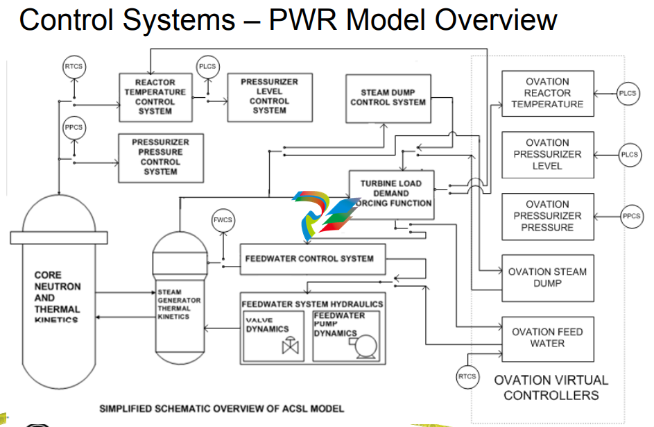
ACSL Model Configuration Overview ACSL Model Configuration Overview
● Design/operational data collected from plant, reviewed for
accuracy, p , y ( p ) com
pleteness, consistenc
y
(i.e. no discre
pancies
)
● Configuration data loaded into ACSL based plant model
● The plant-specific ACSL plant model is tied into ACSL based
control system models transient cases are evaluated control system models transient cases are evaluated
● Adjustments are made until subject matter expert (SME) is
confident that the plant model and control system models are
respondi tl ng correctl
y
● SME peer check is also performed to ensure suitability for use
● Once model review & res
p p,p onse checks are com
plete, set
point
sensitivity tests are performed
● ACSL based control system model is disconnected and Ovation
control system is switched in; transients cases are re
-performed
16
control system is switched in; transients cases are re performed
and evaluated
Setpoint Determination Setpoint Determination
● Dynamic transient analysis using high-fidelity ACSL model of
p g rocess runnin
g faster than real time
– Steam Generators or Reactor Vessel
– Steam Dump or Steam Bypass – Reactor Pressure Regulation
– Feed System Feed System
– Steam System
– NSSS (core)
● Evaluation response over the full range of operation and
operational transient conditions
– Normal Operation
– Contingency Operations
● Provides high confidence set of initial tunings
● Pr
ovides
a basis for v
alidati
on
of desig
n
Feed Water Control Design Overview
- Example
● S/G Model Description Example
– Nodes of S/G Model
Feed Water Control Design Overview Example
Nodes of S/G Model
– Primary side tubes
– Secondary side tube bundle area (inside of wrapper)
– Riser section (from bundle exit through primary separators) Riser section (from bundle exit through primary separators)
– Upper downcomer (generally downcomer area from start of transition cone to top of primary separators)
– Lower downcomer (straight cylindrical portion of downcomer belo transition cone) below transition cone)
– Steam dome (region above top of risers or primary separators)
– Separate mass/energy balances for exit properties
– Momentum balance performed to calculate change in
various section flow rates
Feed Water Control Design Overview Feed Water Control Design Overview
- Example Example
● Proven Validation Approach
– SWIL (
S
oft
ware In
Loop) l d l lid ti t ti ) close
d loop valid
ation
testing
with plant specific model ensures realistic plant
operational response
–
ACSL Models validated for various SG’s and now
Reactor Vessels (BWR)
Westinghouse
B&W Canada (5 Units)
AREVA (5 Units)
C b ti E i i (4 U it ) Com
bustion
Eng
ineering (4
U
nits)
GE BWR 6 Reactor Vessel – Clinton and River Bend
Feed Water Control Design Overview Feed Water Control Design Overview
- Example Example
● Proven Control Application
– SWIL l d SWIL close
d
-l l oop, real-ti t ti id lid ti time
testing provides valid
ation,
allows integration test of graphics, alarms and controls with
plant operators before system is manufactured
Setpoints verified for operational transients
(determined previously with ACSL control system
models)
Dynamic set points (Gain, Integral & Derivative) for PID
are carefully chosen
For responsiveness to transients For responsiveness to transients
For near steady state conditions
Results in no tuning during plant startup
Software In Loop (SWIL) Software In Loop (SWIL)
● Upon completion of setpoint analyses, the ACSL plantspecific control model is switched to Ovation virtual
controllers for real-time, closed-loop validation testing
● Verifies delivered system contains the proper setpoints and
control logic as presented in the functional requirement
documents
● Test performed by Subject Matter Expert along with detailed
checks of control logic tuning to verify that setpoints match
the intended design
Feed Water Application (SWIL) Feed Water Application (SWIL)
● Validation of plant dynamic performance using transient test
scenariE l os;
Examples:
– Ramp Load Increase from 1% Power to Turbine Synchronization Power Level at 1%/min
– Turbine Synchronization and Initial Load Pickup
– T bi T i With t R t T i ( t i t l l) Turbine
Trip Without Reactor
Trip (at appropriate power level)
– 100% Power ±10% Load Swing
– 100% Power Ramp Load Decrease to 15% Power at 5%/min (bringing on various pumps at the
appropriate power)
– 1 % 100% %/ ( ff 15
% Power Ramp Load Increase to 100% Power at 5%/min (taking off various pumps at the
appropriate power level)
– Large Load Rejection (dependent upon plant design typically either 50 or 100% capability)
– Loss of One Feedwater Pump
– Level Setpoint Step at 5% Power
– Level Setpoint Step at 100% Power
– Level Setpoint Step at 50% Power with One Feedwater Pump Operating
– Level Set
point Ste
p at 50% Power with Two Feedwater Pum
ps O
peratin
g.
Feed Water Application Software (SWIL) Feed Water Application Software (SWIL)
● Key Customer representatives participate in testing:
– Operations, systems engineering, training, etc.
● Results of the testing (trend plots, Control Builder mark-ups,
and logbook entries) are collected into a test report and
archived.
● Upon successful completion of this testing, the application
software is ready for loading into simulator and FAT on
target plant hardware.
Westinghouse Test Plan Overview Westinghouse Test Plan Overview
● Covers validation test approach.
● Each test phase builds upon previous testing in an Each test phase builds upon previous testing in an
overlapping, structured approach in the order listed below:
1. Initial Software Debug Tests
2. Testing of Application Software (includes dynamic SWIL tests)
3. Simulator Testing
4. FAT 1: Target Hardware (power up, controller/network FAT 1: Target Hardware (power up, controller/network
redundancy failover & I/O checkout)
5. FAT 2: Base System Hardware/software (network, OWS, EWS,
AVS Domain workstation and system security configurations AVS, Domain workstation and system security configurations
6. FAT 3: Including signal validation, graphics, hardware alarms
output redundancy and application hardware )
7 Site Testing site acceptance tests and po er ascension test
25
. Site Testing
– site acceptance tests and po
wer ascension test
Feed Water (FW) Control Systems Feed Water (FW) Control Systems
In delivering digital FW control systems,
W ti h li Westing
house applies:
• High Quality Application Software Development
Process
– Software Requirements Document
– Software Description Document
– S ft Lif l Pl S
oftware Lifecycle Plan
– Failure Modes and Affects Analysis (software and hardware)
– Software Hazards Analysis
– P i t t ith 10CFR50 A di B Processes consis
ten
t with 10CFR50
Appendix
B
where commercial grade application software can be
applied in critical applications
Feed Water (FW) Control Systems Feed Water (FW) Control Systems
Westinghouse NA uses “defense in design” to
ens re deli er of a high q alit prod ct ens
ure deli
very of
a high
q
uality prod
uct:
• Plant Specific Models and validation testing with application in closed
loop demonstrates deterministic behavior of the application early in
d i es gn process
• Applications are partitioned on controllers such as not to cause failures
that could add positive reactivity or effect plant design basis
• Reliance on the control network is limited Reliance on the control network is limited
– controllers and associated controllers and associated
I/O can continue to function with loss of network
• I/O designed on controller loss to revert to known or benign state
• For critical control component, a hard control station is provided to For critical control component,
a hard control station is provided to
operator manual control – another layer of redundancy
• Redundancy of system components at all levels
Existing Analog Feed Water Control Existing Analog Feed Water Control
● Historically, Steam Generator Water Level has
been difficult to contro
l
– Analog-based systems are limited
– Per INPO data; second leading system for plant trip
– Steam Generator (SG) shrink and swell phenomena
– Steam & Steam
& feedwater feedwater measurement unreliable at low power levels measurement unreliable at low power levels
– Manual control with multiple operators required to bring up unit
– Prone to single points of failure
Analog Inputs – no active redundancy
Manual operator action in detecting input failures
Modulating Outputs single driver card
29
Modulating Outputs
– single driver card
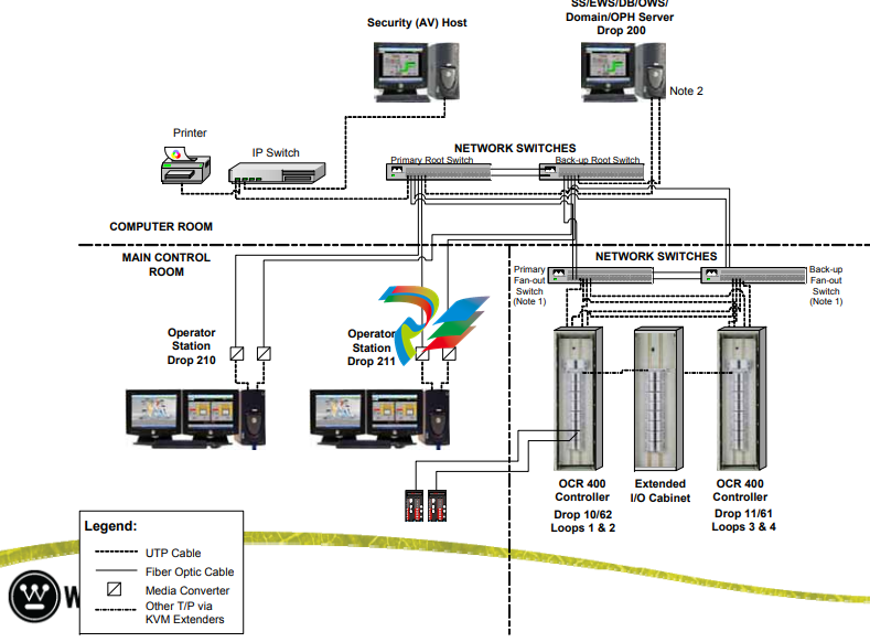
Typical Advanced Digital Feed Water
System (ADFCS) Configuration System (ADFCS) Configuration
● 1,2, 3 or 4 Redundant Controllers:
● HMI -T O t W k t ti ith ft t l Two
Opera
tor
Wor
k
s
t
ations with soft con
trols
– M/A Stations for FW Valve & FP Controls
● One Engineer One Engineer s/Data ’s/Data Base Server Workstation Base Server Workstation
● Network Equipment – Fast Ethernet Switches
● Anti-virus Station
● New Cabinets or retrofit of existing cabinets
● SLIM M/A’s for Main, Bypass and Feed Pumps
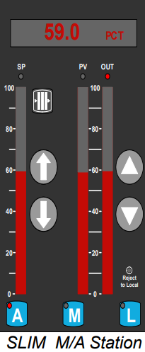
ADFCS
– Main Control Room Main Control Room
● Redundant operator stations & LCD
displays in MCR displays in MCR 59 0 PCT
● SLIM M/A’s for all modulating valves, &
feed pumps
Add d l f d d
59.0 PCT
100
SP PV OUT
100
Add
e
d layer o
f re
dun
dancy upon
controller failure
Works seamlessly with soft control
80
60 60
80
● Remove signal selector switches
● Remove select recorders – steam/feed
water, wide and narrow ran
ge level 20
40
20
40
, g
● Remove individual channel indicators &
replace with median
● Select indicators can remain
“live
”
Typical ADFCS Architecture Typical ADFCS Architecture
ADFCS
– Design Overview Design Overview
● Improved system reliability via signal selectors
– Narrow Range Level
– Wide Range Level
– Feedwater Flow
– Steam Flow
– Steam Pressure
– Feedwater Tem
perature
– Turbine Impulse Pressure or Nuclear Power
– Feedwater Header Pressure
( ) FP turbine runback)
● Improve System performance by integrating feed pump governor controls
ADFCS
– Design Overview Design Overview
● Proven Control Application – third generation
design consistent with AP1000 design consistent with AP1000
– Low and High Power Controllers
Bumpless Transfer between Low Power and High
P C t lM d Power
Con
tro
l
M
o
de
– Feedwater Temperature Compensation
Low Power Level Controller gain & reset adjusted Low Power Level Controller gain
& reset adjusted
based on feedwater temperature
Compensates for the effects of shrink and swell in
ll t eve
l response
to fd t ee
dwa
ter fl i ti flow variations
– High Power Level Controller proportional gain and
integral time adjusted based on steam flow
35
integral time adjusted based on steam flow
ADFCS
– Design Overview Design Overview
● Proven Control Application (cont’d)
– Load Index Load Index
Wide Range Level
Anticipates need for flow change at low power
– Automatic transition from bypass valve to main feed Automatic transition from bypass valve to main feed water regulation valve
– Capability of operating with one valve in manual and other in auto other in auto
– Control Valve Linearization & Performance
Compensates for non-linearities in valve characteristics and ensures an effective and stable
control response
Position feedback provides means to detect sticking or sluggish valve response and alert the operator
ADFCS
– Design Overview Design Overview
● Proven Control Application (cont’d)
– F d d d d i l l t d f ti f Fee
d pump spee
d
deman
d is calcula
t
e
d as a
function o
f
feed water flow demand
Provide adequate pump head to ensure flow to the
steam generators is maintained during transients
Coordinated automatic control of steam driven feed
pp g um
ps when inte
grated into ADFCS
ADFCS
– Design Overview Design Overview
● Proven Control Application (cont’d)
– S it h t M l d i t l ith S
wit
c
h
to
Manual mo
de in new sys
tem only occurs with
complete Narrow Range Level failure; otherwise system
remains in Automatic for all other failures
Steam or feedwater flow input failure; system reverts Steam or feedwater flow input failure; system reverts
to single element control with a reduced steam
generator narrow range level error input to the flow
controller PID. controller PID.
Steam pressure, feedwater temperature and
feedwater header pressure input failures; system
uses a constant value of the signal that is
representative of the signal prior to the failure
Advanced Digital Feed Water Advanced Digital Feed Water
● Benefits
– Proven 3rd Generation Design used on Westinghouse and CE plants, deployed
in eleven units with two additional in next two years; common design with
AP1000
– Standardized proven and enhanced control logic used for highly reliable Standardized, proven and enhanced control logic used for highly reliable
operational performance allowing operational maneuvers with no level deviation
– Auto control over full power range (1-100%), heatup/cooldown (optional)
– Auto, seamless transition between main/bypass feed water regulation valves
– Bumpless transition from Automatic mode to Manual mode and back
– Allows Integrated governor control and protection of main feed water pump
speed
– Plant
-specific dynamic analysis per SWIL addresses plant components & specific dynamic analysis per SWIL addresses plant components
&
operational conditions
– Supports transient capability with reduced risk of reactor trip
– Minimized field tunin
g and risk of dela
ys at startup
Advanced Digital Feed Water Advanced Digital Feed Water
Benefits (cont)
– Integrated governor control and protection of Integrated governor control and protection of
main feed water pump speed governor
– Operational maneuvers with no narrow range
level deviation
– Output redundancy to control valves
available that provides additional layer of
protection against SPV and loss of
red d t t ll dun
dant controllers
– SLIM hard interface operates seamlessly
with Soft Control Interface graphics
– A tomatics s itch to man al and alternate A
utomatics
s
witch to man
ual and alternate
actions
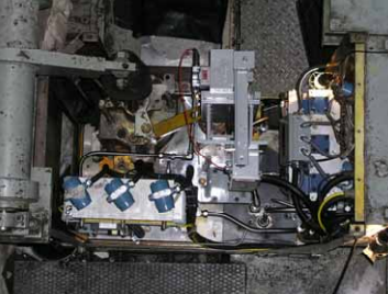
– SONG’s and Almaraz have tripped a feed
pump at power and stayed on line
Almaraz Feed Pump
Turbine
41
pump at power and stayed on line
-
 Hirschmann RS20-1600M2T1SDAEHH03.1.02 Rail Switch
 -
 Hirschmann BRS30-24TX Industrial Rail Switch
 -
 Hirschmann RSPM20-4T14T1EV9HHS999.9.99 Managed Ethernet Switch
 -
 Hirschmann BELDEN RS40-0009CCCCSDAPHH09.0.14 / RS400009CCCCSDAPHH09014
 -
Hirschmann RS40 Rail Switch RS40-0009CCCCSDAE
-
 Hirschmann BELDEN RS30-0802T1T1SDAP / RS300802T1T1SDAP Fully Managed Layer 2 Compact Rail Switch
 -
 Hirschmann BELDEN RS20-0800M2M2SDAUHH / RS200800M2M2SDAUHH
 -
 Hirschmann EAGLE30-04022O6TT999SCCY9HSE3F Industrial Firewall Router Switch
 -
 Hirschmann RS20-1600T1T1SDAEHH09.0.14 RS20 Rail Mount Ethernet Switch
 -
 Hirschmann EAGLE0200T1T1TDDY90000HHE05.3.03 Industrial Security Router
 -
Hirschmann - BELDEN MIPP-AD-1L9P
-
 HIRSCHMANN RSPM20-4Z64Z6TV9HHS9 942 106-999 RAIL SAFETY SWITCH
 -
 HIRSCHMANN FIBEROPTIC MODULE FIP P/N: OZDFIPG3T
 -
 HIRSCHMANN RS20-1600M2M2SDAUHH Ethernet rack-mounted switch
 -
 HIRSCHMANN BELDEN RS20-0400T1T1SDAEHH04.0.01 / RS200400T1T1SDAEHH04001
 -
HIRSCHMANN MM2-4FXM3 MICE Media Module
-
HIRSCHMANN RS20-0800M2M2SDAE Industrial Ethernet Rail Switch
-
 Hirschmann RS20-2400T1T1SDAP / RS20-2400T1T1SDAPHH05.0.02
 -
 GE MLJ1005B010H00C MLJ Digital Synchromism Check
 -
 ALSTOM MICROTECH DX21-M2 Digital Excitation Controller
 -
HIRSCHMANN BRS20-1200ZZZZ-STCY99HHSES
-
 HIRSCHMANN MM3-4FXM2 MICE Media Module
 -
Hirschmann RSB20-0800T1T1SAABHH 8Port ENet Rail Switch RSB20
-
 Hirschmann MACH102-8TP Ethernet Switch
 -
 SAACKE DDZ-M marine steam pressure atomizer
 -
 SAACKE SKV-A marine rotary cup atomizer
 -
 SAACKE Seavis HMI05e
 -
 Kollmorgen MMC-SD-2.0-230 Servo Drive 100-240VAC 2KW 10A Output 3PH 100-240VAC
 -
 Kollmorgen Servo drive CR10550
 -
 Kollmorgen AKD-P01207-NACN-0054 Servo Driver
 -
 Kollmorgen S406M-CA-036 Servostar
 -
.png) Kollmorgen AKD-B02407-NAAN-0000 Digital Servo Drive
Kollmorgen AKD-B02407-NAAN-0000 Digital Servo Drive -
 Kollmorgen SERVOSTAR S406AM-CA Digital Servo Drive
 -
 KOLLMORGEN SERVOSTAR 603-AS SERVO AMPLIFIER_SERVOSTAR603AS_S60301
 -
Kollmorgen S700 Servo Controller (S70602-NANANA-NA)
-
 Kollmorgen MPK411 controller
 -
 KOLLMORGEN MMC-SD-1.3-460-D Smart Drive
 -
 KOLLMORGEN AKM21C-CKB2AA-00 / AKM21CCKB2AA00 Servomotor
 -
 BECKHOFF AX5106-0000-0200 | Digital Compact Servo Drives 1-channel
 -
 BECKHOFF C3620-0000 INDUSTRIAL COMPUTER (MOTORSHELVES)
 -
 Beckhoff EK1960-0000 TwinSAFE Compact Controller
 -
 Beckhoff C6930-0050 Control Cabinet Industrial PC
 -
 Beckhoff CP7711-0001-0030 Industrial Computer Detection
 -
 Beckhoff CX1001-0111 Embedded PC CPU Module
 -
 Beckhoff C6017-0020 | Ultra-compact Industrial PC
 -
 Beckhoff EK1322 | 2-port EtherCAT P junction with feed-in
 -
 Beckhoff CP2219-0010 Panel
 -
 BECKHOFF C6015-0020 ULTRA COMPACT INDUSTRIAL PC
 -
 BECKHOFF CX2030-0120/Standard CPU Module Embedded PC Windows PLC controller
 -
 Beckhoff CP7721-1090-0020 Panel PC
 -
 Beckhoff PC CPU Module CX5130-0175
 -
 Beckhoff C6920-0050 Control Cabinet
 -
 Beckhoff EL6631 EtherCAT 2-Port Communication Interface, Profinet RT Controller
 -
 Beckhoff CP6202-0001-0060 touch screen panel PC
 -
 Beckhoff CP3916-1002-0000 Multi-Touch Control Panel
 -
 Beckhoff EP1809-0021 | EtherCAT Box, 16-channel digital input, 24 V DC, 3 ms, M8Preferred type
 -
 Beckhoff CX8190 PLC Embedded Industrial PC Ethernet Controller
 -
 Beckhoff CX2100-0914 Power Supply for External
 -
 Beckhoff Automation CP6906-0001-0000 HMI
 -
 Beckhoff EP7342-0002 Module
 -
 Beckhoff CX1020-0112 / CX1100-0910 / CX1020-N010 / CX1100-0003 Windows CPU
 -
 Beckhoff EP7211-0034 EtherCAT Box 1 Channel Motion Interface
 -
 Beckhoff C6240-0030 Control cabinet Industrial PC
 -
 beckhoff motherboard CB1052-0004 CB1052-0004
 -
 Beckhoff AX2006-AS Servo Drive / Variable Frequency Drive
 -
BECKHOFF CP6207-0001-0020 NSMP
-
 Beckhoff C6930-1142-0060 Industrial Computer
 -
 Beckhoff FC7501-0000 interface card
 -
 Beckhoff CX5140-0175 Embedded PC PLC CPU CX5140 Industrial Controller
 -
 Beckhoff CP7802-1100-0010: High-End IP65 Control Panel with DVI/USB Extended Interface
 -
BECKHOFF CP3716-1058-0010 CONTROL PANEL
-
 Beckhoff AX8108-0000 Single-Axis Module
 -
 Beckhoff CU8851-0000 | USB extension, USB Extended 2.0 receiver box
 -
Beckhoff C6017-0030 | Ultra-compact Industrial PC
-
 Beckhoff CX1001-0120/CX10010120.cx1000-n001.cx1000-n000 System Overview
 -
 Beckhoff CPU Module CX5140-0155/4GB CPU Module
 -
 Beckhoff CP6533-0001-005: Built-in Panel PC with High-Definition Multi-Touch Control
 -
 Beckhoff EL5042 | EtherCAT Terminal, 2-channel encoder interface, BiSS® C
 -
 Beckhoff C6920-1080-0040: Premium Control Cabinet Industrial PC
 -
 Beckhoff C6920-0060 | Control cabinet Industrial PC
 -
 Beckhoff Embedded-PC CX5010-1121
 -
 Beckhoff CB3050-0010 Mainboard Motherboard
 -
 Beckhoff PLC module CX1020-0000 Basic CPU module (service phase)
 -
 Beckhoff CP7812-1056-0010 15" Multitouch Display Control Panel
 -
 Beckhoff CX5120-0115 /2GB Controller Module
 -
 Beckhoff CP7201-1000-0000 Industrial Panel PC
 -
 Beckhoff Servo Motor AM8061-0JH1-0000
 -
 BECKHOFF CP6503-0001-0050 Built-in Panel PC
 -
Beckhoff CP3919-0010 Display G190ETN01.2 19" PCT V04. Multi-touch Control Panel
-
 Beckhoff CX5110-0112-9020/000368201 Embedded PC Intel Atom Processor
 -
 Beckhoff AX8206-0000 Dual-Axis Module
 -
Beckhoff Nail Operating Terminal CP7032-1031-0010
-
Beckhoff AM8042-0EH1-0000 Servomotor 4.10 Nm (M0), F4 (87 mm)
-
 Beckhoff EK9300 Beckhoff CPU Module
 -
Beckhoff CP3224-0020 Multitouch-Panel-PC
-
 Beckhoff CP2712-0000 12.1" 24VDC Touch Screen WMD0
 -
 BECKHOFF CX5240-0195 / 0000289234 Embedded PC 40 GB CFast Card
 -
 Beckhoff CP6932-1000-0000 Control Panel
 -
 BECKHOFF CX5120-0121 PLC Module
 -
 Beckhoff EL3218 | EtherCAT Terminal, 8-channel analog input
 -
Beckhoff C6640-0050 | Control cabinet Industrial PC
-
 Beckhoff Cx5130-0120/4GB Embedded-PC
 -
 BECKHOFF CX2030-0122 PLC PROCESSOR
 -
 BECKHOFF CX5020-0122 Controller Module
 -
 Beckhoff CP3915-0000 Multitouch Panel
 -
 BECKHOFF EL3014 | EtherCAT Terminal
 -
 BECKHOFF Industrial Computer c6920-1057-0030
 -
 Beckhoff CX5130-0141/4GB CX5130-0141 Embedded PC
 -
 Beckhoff C6240-1052-0040 4-086-06-3073 Industrial Computer
 -
 Beckhoff CX5140-0135 /4GB High-Performance Embedded Industrial PC
 -
 Beckhoff C6515-1001-0000 Industrial PC
 -
 Beckhoff AX5103-0000-0200 - Digital Compact Servo Drives
 -
 Beckhoff CX2030-0130-1003/4GB Basic CPU module
 -
 Beckhoff AX8620-0000 Power Supply Module
 -
 Beckhoff CX9020-0111 module with
 -
 Beckhoff EL7332 PLC Module
 -
 BECKHOFF CP7709-0001-0020 HMI
 -
 Beckhoff CX5120-0155/2GB Embedded PC
 -
 BECKHOFF CP7037-1037-0010 OPERATOR INTERFACE TOUCHSCREEN
 -
 Beckhoff EK9000 | ModbusTCP/UDP Bus Coupler
 -
 Beckhoff Touch Panel Screen CP6020 -0000-0000
 -
 Beckhoff CX2020-0121 Module FAST Shipping
 -
 Beckhoff CX2030-0125 Basic CPU Module
 -
 Beckhoff CP3918-0000 Multi-Touch 18.5" Control Panel
 -
 Automotion LC4A00010 DC BL Motor Control, ATS, Sub Assy, SCP, 115VAC,
 -
 500T-115VAC - VAS ENGINEERING - DORIC 500 SERIES DIGITAL TEMP INDICATOR
 -
 Honeywell X-DCS2000/EN Digital Integrated System Manager 50/60Hz 100-240V #4
 -
 Kollmorgen S60600 Servostar600 606-Fan 4 kVA, 6 A, 3 X 230 - 480 V


