
ABBIndustrialIT Panel 800 - PP865 Version 5.1 Hardware and Installation
NOTICE
This document contains information about one or more ABB products and may include a
description of or a reference to one or more standards that may be generally relevant to
the ABB products. ABB may have one or more patents or pending patent applications
protecting the intellectual property in the ABB product(s) described in this publication.
The presence of any such description of a standard or reference to a standard is not a
representation that all of the ABB products referenced in this document support all of the
features of the described or referenced standard. In order to determine the specific features supported by a particular ABB product, the reader should consult the product specifications for the particular ABB product.
The information in this document is subject to change without notice and should not be
construed as a commitment by ABB. ABB assumes no responsibility for any errors that
may appear in this document.
In no event shall ABB be liable for direct, indirect, special, incidental or consequential
damages of any nature or kind arising from the use of this document, nor shall ABB be
liable for incidental or consequential damages arising from use of any software or hardware described in this document.
This document and parts thereof must not be reproduced or copied without written permission from ABB, and the contents thereof must not be imparted to a third party nor used
for any unauthorized purpose.
The software or hardware described in this document is furnished under a license and
may be used, copied, or disclosed only in accordance with the terms of such license.
This product meets the requirements specified in EMC Directive 89/336/EEC and in Low
Voltage Directive 72/23/EEC.
TRADEMARKS
All rights to copyrights, registered trademarks, and trademarks reside with their respective owners.
Copyright © 2005-2011 by ABB.
All rights reserved.
Release: December 2011
Document number: 3BSE043448R501
Section 1 Introduction
General
The Panel 800 operator panel is developed to satisfy the demands of humanmachine communication. Built-in functions such as displaying and controlling text,
dynamic indication, time channels, alarm and recipe handling are included.
The operator panel work, for the most part, in an object-oriented way, making it
easy to understand and use. The configuration operation of the panel is made in a
personal computer, using the configuration tool Panel Builder 800. The project is
then transferred and stored in the operator panel.
The operator panel can be connected to many types of automation equipment, such
as PLCs, servos or drives. In this manual the expression “the controller“ is used as a
general term for the connected equipment.
This manual explains how to install the operator panel. Please refer to the manual
Panel Builder 800, Programming and Installation (3BSE043445Rxxx) for further
information.
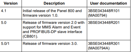
The release history of the Panel 800 is presented below.
Warning, Caution, Information, and Tip Icons
This publication includes Warning, Caution, and Information where appropriate
to point out safety related or other important information. It also includes Tip to
point out useful hints to the reader. The corresponding symbols should be
interpreted as follows:
Although Warning hazards are related to personal injury, and Caution hazards are
associated with equipment or property damage, it should be understood that
operation of damaged equipment could, under certain operational conditions, result
in degraded process performance leading to personal injury or death. Therefore,
fully comply with all Warning and Caution notices.
5.1 Release of firmware version 4.0. 3BSE043448R401
(MA00794B)
5.1/3 Release of PP865A 3BSE043448R501
Electrical warning icon indicates the presence of a hazard which could result in
electrical shock.
Warning icon indicates the presence of a hazard which could result in personal
injury.
Caution icon indicates important information or warning related to the concept
discussed in the text. It might indicate the presence of a hazard which could
result in corruption of software or damage to equipment/property.
Information icon alerts the reader to pertinent facts and conditions.
Tip icon indicates advice on, for example, how to design your project or how to
use a certain function
Section 2 Safety Precautions
Both the installer and the owner and/or operator of the operator panel must read and
understand this installation manual.
UL and cUL Installation
• This equipment is suitable for use in Class I, Division 2, Groups A, B, C and D
OR non-hazardous locations only. [Combinations of equipment in your system
are subject to investigation by the local Authority Having Jurisdiction at the
time of installation].
• Maximum ambient temperature 40 °C when mounted horizontal or 50 °C when
mounted vertical.
• WARNING – EXPLOSION HAZARD – Do not disconnect equipment unless
power has been removed or the area is known to be non-hazardous.
• For Canada also AVERTISSEMENT – RISQUE D’EXPLOSION – AVANT
DE DECONNECTER L’EQUIPEMENT, COUPER LE COURANT
OUS’ASSURER QUE L‘EMPLACEMENT EST DESIGNE NON
DANGEREUX.
• WARNING – EXPLOSION HAZARD - Substitution of components may
impair suitability for Class I, Division 2.
• For Canada also AVERTISSEMENT – RISQUE D’EXPLOSION – LA
SUBSTITUTION DE COMPOSANTS PEUT RENDRE CE MATERIEL
INACCEPTABLE POUR LES EMPLACEMENTS DE CLASSE I, DIVISION
2.
• WARNING – EXPLOSION HAZARD – only UL and cUL approved
expansion units are allowed to be connected to the port designated
“EXPANSION”. At the moment there are no such units evaluated or allowed.
• WARNING – EXPLOSION HAZARD - Do not replace expansion unit unless
power has been switched off or the area is known to be non-hazardous.
• This product contains battery, this must only be changed in an area known to be
non-hazardous. Permitted types are shown in the Section 4, Technical Data.
• For use on a flat surface of a type 4X enclosure indoor use only.
• To make wiring connections to the power supply connector, use an AWG 28-12
cable and a tightening torque of min. 0.5 Nm.
General
• Read the safety precautions carefully.
• Check the delivery for transportation damage. If damage is found, notify the
supplier as soon as possible.
• Do not use the operator panel in an environment with high explosive hazards.
• The supplier is not responsible for modified, altered or reconstructed
equipment.
• Use only parts and accessories manufactured according to specifications of the
supplier.
• Read the installation and operating instructions carefully before installing,
using or repairing the operator panel.
• Never allow fluids, metal filings or wiring debris to enter any openings in the
operator panel. This may cause fire or electrical shock.
• Only qualified personnel may operate the operator panel.
• Storing the operator panel where the temperature is lower/higher than
recommended in this manual can cause the LCD display liquid to
congeal/become isotopic.
• The LCD display liquid contains a powerful irritant. In case of skin contact,
wash immediately with plenty of water. In case of eye contact, hold the eye
open, flush with plenty of water and get medical attention.
• The figures in this manual serves an illustrative purpose. Because of the many
variables associated with any particular installation, the supplier cannot assume
responsibility for actual use based on the figures.
• The supplier neither guarantees that the operator panel is suitable for your
particular application, nor assumes responsibility for your product design,
installation or operation.
During Installation
• The operator panel is designed for stationary installation on a plane surface,
where the following conditions are fulfilled:
– no high explosive risks.
– no strong magnetic fields.
– no direct sunlight.
– no large, sudden temperature changes.
• Install the product according to the accompanying installation instructions.
• Ground the product according to the accompanying installation instructions.
• Only qualified personnel may install the operator panel.
• Separate the high voltage, signal and supply cables.
• Make sure that the voltage and polarity of the power source is correct before
connecting the product to the power outlet.
• Peripheral equipment must be appropriate for the application and location.
During Use
• Keep the operator panel clean.
• Emergency stop and other safety functions may not be controlled from the
operator panel.
• Do not use too much force or sharp objects when touching the keys, display
etc.
Service and Maintenance
• Only qualified personnel should carry out repairs.
• The agreed warranty applies.
• Before carrying out any cleaning or maintenance operations, disconnect the
equipment from the electrical supply.
• Clean the display and surrounding front cover with a soft cloth and mild
detergent.
• Replacing the battery incorrectly may result in explosion. Only use batteries
recommended by the supplier.
Dismantling and Scrapping
• The operator panel or parts thereof shall be recycled according to local
regulations.
• The following components contain substances that might be hazardous to
health and the environment: lithium battery, electrolytic capacitor and display.
Section 3 Installation
Space Requirements
• Installation plate thickness: 1.5 - 9.0 mm (0.06 - 0.35 inch)
• Space requirements when installing the operator panel:
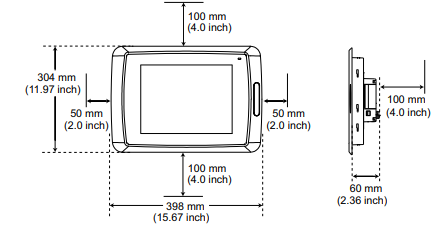
The openings on the enclosure are for air convection. Do not cover these
openings.
-
 Hirschmann RS20-1600M2T1SDAEHH03.1.02 Rail Switch
 -
 Hirschmann BRS30-24TX Industrial Rail Switch
 -
 Hirschmann RSPM20-4T14T1EV9HHS999.9.99 Managed Ethernet Switch
 -
 Hirschmann BELDEN RS40-0009CCCCSDAPHH09.0.14 / RS400009CCCCSDAPHH09014
 -
Hirschmann RS40 Rail Switch RS40-0009CCCCSDAE
-
 Hirschmann BELDEN RS30-0802T1T1SDAP / RS300802T1T1SDAP Fully Managed Layer 2 Compact Rail Switch
 -
 Hirschmann BELDEN RS20-0800M2M2SDAUHH / RS200800M2M2SDAUHH
 -
 Hirschmann EAGLE30-04022O6TT999SCCY9HSE3F Industrial Firewall Router Switch
 -
 Hirschmann RS20-1600T1T1SDAEHH09.0.14 RS20 Rail Mount Ethernet Switch
 -
 Hirschmann EAGLE0200T1T1TDDY90000HHE05.3.03 Industrial Security Router
 -
Hirschmann - BELDEN MIPP-AD-1L9P
-
 HIRSCHMANN RSPM20-4Z64Z6TV9HHS9 942 106-999 RAIL SAFETY SWITCH
 -
 HIRSCHMANN FIBEROPTIC MODULE FIP P/N: OZDFIPG3T
 -
 HIRSCHMANN RS20-1600M2M2SDAUHH Ethernet rack-mounted switch
 -
 HIRSCHMANN BELDEN RS20-0400T1T1SDAEHH04.0.01 / RS200400T1T1SDAEHH04001
 -
HIRSCHMANN MM2-4FXM3 MICE Media Module
-
HIRSCHMANN RS20-0800M2M2SDAE Industrial Ethernet Rail Switch
-
 Hirschmann RS20-2400T1T1SDAP / RS20-2400T1T1SDAPHH05.0.02
 -
 GE MLJ1005B010H00C MLJ Digital Synchromism Check
 -
 ALSTOM MICROTECH DX21-M2 Digital Excitation Controller
 -
HIRSCHMANN BRS20-1200ZZZZ-STCY99HHSES
-
 HIRSCHMANN MM3-4FXM2 MICE Media Module
 -
Hirschmann RSB20-0800T1T1SAABHH 8Port ENet Rail Switch RSB20
-
 Hirschmann MACH102-8TP Ethernet Switch
 -
 SAACKE DDZ-M marine steam pressure atomizer
 -
 SAACKE SKV-A marine rotary cup atomizer
 -
 SAACKE Seavis HMI05e
 -
 Kollmorgen MMC-SD-2.0-230 Servo Drive 100-240VAC 2KW 10A Output 3PH 100-240VAC
 -
 Kollmorgen Servo drive CR10550
 -
 Kollmorgen AKD-P01207-NACN-0054 Servo Driver
 -
 Kollmorgen S406M-CA-036 Servostar
 -
.png) Kollmorgen AKD-B02407-NAAN-0000 Digital Servo Drive
Kollmorgen AKD-B02407-NAAN-0000 Digital Servo Drive -
 Kollmorgen SERVOSTAR S406AM-CA Digital Servo Drive
 -
 KOLLMORGEN SERVOSTAR 603-AS SERVO AMPLIFIER_SERVOSTAR603AS_S60301
 -
Kollmorgen S700 Servo Controller (S70602-NANANA-NA)
-
 Kollmorgen MPK411 controller
 -
 KOLLMORGEN MMC-SD-1.3-460-D Smart Drive
 -
 KOLLMORGEN AKM21C-CKB2AA-00 / AKM21CCKB2AA00 Servomotor
 -
 BECKHOFF AX5106-0000-0200 | Digital Compact Servo Drives 1-channel
 -
 BECKHOFF C3620-0000 INDUSTRIAL COMPUTER (MOTORSHELVES)
 -
 Beckhoff EK1960-0000 TwinSAFE Compact Controller
 -
 Beckhoff C6930-0050 Control Cabinet Industrial PC
 -
 Beckhoff CP7711-0001-0030 Industrial Computer Detection
 -
 Beckhoff CX1001-0111 Embedded PC CPU Module
 -
 Beckhoff C6017-0020 | Ultra-compact Industrial PC
 -
 Beckhoff EK1322 | 2-port EtherCAT P junction with feed-in
 -
 Beckhoff CP2219-0010 Panel
 -
 BECKHOFF C6015-0020 ULTRA COMPACT INDUSTRIAL PC
 -
 BECKHOFF CX2030-0120/Standard CPU Module Embedded PC Windows PLC controller
 -
 Beckhoff CP7721-1090-0020 Panel PC
 -
 Beckhoff PC CPU Module CX5130-0175
 -
 Beckhoff C6920-0050 Control Cabinet
 -
 Beckhoff EL6631 EtherCAT 2-Port Communication Interface, Profinet RT Controller
 -
 Beckhoff CP6202-0001-0060 touch screen panel PC
 -
 Beckhoff CP3916-1002-0000 Multi-Touch Control Panel
 -
 Beckhoff EP1809-0021 | EtherCAT Box, 16-channel digital input, 24 V DC, 3 ms, M8Preferred type
 -
 Beckhoff CX8190 PLC Embedded Industrial PC Ethernet Controller
 -
 Beckhoff CX2100-0914 Power Supply for External
 -
 Beckhoff Automation CP6906-0001-0000 HMI
 -
 Beckhoff EP7342-0002 Module
 -
 Beckhoff CX1020-0112 / CX1100-0910 / CX1020-N010 / CX1100-0003 Windows CPU
 -
 Beckhoff EP7211-0034 EtherCAT Box 1 Channel Motion Interface
 -
 Beckhoff C6240-0030 Control cabinet Industrial PC
 -
 beckhoff motherboard CB1052-0004 CB1052-0004
 -
 Beckhoff AX2006-AS Servo Drive / Variable Frequency Drive
 -
BECKHOFF CP6207-0001-0020 NSMP
-
 Beckhoff C6930-1142-0060 Industrial Computer
 -
 Beckhoff FC7501-0000 interface card
 -
 Beckhoff CX5140-0175 Embedded PC PLC CPU CX5140 Industrial Controller
 -
 Beckhoff CP7802-1100-0010: High-End IP65 Control Panel with DVI/USB Extended Interface
 -
BECKHOFF CP3716-1058-0010 CONTROL PANEL
-
 Beckhoff AX8108-0000 Single-Axis Module
 -
 Beckhoff CU8851-0000 | USB extension, USB Extended 2.0 receiver box
 -
Beckhoff C6017-0030 | Ultra-compact Industrial PC
-
 Beckhoff CX1001-0120/CX10010120.cx1000-n001.cx1000-n000 System Overview
 -
 Beckhoff CPU Module CX5140-0155/4GB CPU Module
 -
 Beckhoff CP6533-0001-005: Built-in Panel PC with High-Definition Multi-Touch Control
 -
 Beckhoff EL5042 | EtherCAT Terminal, 2-channel encoder interface, BiSS® C
 -
 Beckhoff C6920-1080-0040: Premium Control Cabinet Industrial PC
 -
 Beckhoff C6920-0060 | Control cabinet Industrial PC
 -
 Beckhoff Embedded-PC CX5010-1121
 -
 Beckhoff CB3050-0010 Mainboard Motherboard
 -
 Beckhoff PLC module CX1020-0000 Basic CPU module (service phase)
 -
 Beckhoff CP7812-1056-0010 15" Multitouch Display Control Panel
 -
 Beckhoff CX5120-0115 /2GB Controller Module
 -
 Beckhoff CP7201-1000-0000 Industrial Panel PC
 -
 Beckhoff Servo Motor AM8061-0JH1-0000
 -
 BECKHOFF CP6503-0001-0050 Built-in Panel PC
 -
Beckhoff CP3919-0010 Display G190ETN01.2 19" PCT V04. Multi-touch Control Panel
-
 Beckhoff CX5110-0112-9020/000368201 Embedded PC Intel Atom Processor
 -
 Beckhoff AX8206-0000 Dual-Axis Module
 -
Beckhoff Nail Operating Terminal CP7032-1031-0010
-
Beckhoff AM8042-0EH1-0000 Servomotor 4.10 Nm (M0), F4 (87 mm)
-
 Beckhoff EK9300 Beckhoff CPU Module
 -
Beckhoff CP3224-0020 Multitouch-Panel-PC
-
 Beckhoff CP2712-0000 12.1" 24VDC Touch Screen WMD0
 -
 BECKHOFF CX5240-0195 / 0000289234 Embedded PC 40 GB CFast Card
 -
 Beckhoff CP6932-1000-0000 Control Panel
 -
 BECKHOFF CX5120-0121 PLC Module
 -
 Beckhoff EL3218 | EtherCAT Terminal, 8-channel analog input
 -
Beckhoff C6640-0050 | Control cabinet Industrial PC
-
 Beckhoff Cx5130-0120/4GB Embedded-PC
 -
 BECKHOFF CX2030-0122 PLC PROCESSOR
 -
 BECKHOFF CX5020-0122 Controller Module
 -
 Beckhoff CP3915-0000 Multitouch Panel
 -
 BECKHOFF EL3014 | EtherCAT Terminal
 -
 BECKHOFF Industrial Computer c6920-1057-0030
 -
 Beckhoff CX5130-0141/4GB CX5130-0141 Embedded PC
 -
 Beckhoff C6240-1052-0040 4-086-06-3073 Industrial Computer
 -
 Beckhoff CX5140-0135 /4GB High-Performance Embedded Industrial PC
 -
 Beckhoff C6515-1001-0000 Industrial PC
 -
 Beckhoff AX5103-0000-0200 - Digital Compact Servo Drives
 -
 Beckhoff CX2030-0130-1003/4GB Basic CPU module
 -
 Beckhoff AX8620-0000 Power Supply Module
 -
 Beckhoff CX9020-0111 module with
 -
 Beckhoff EL7332 PLC Module
 -
 BECKHOFF CP7709-0001-0020 HMI
 -
 Beckhoff CX5120-0155/2GB Embedded PC
 -
 BECKHOFF CP7037-1037-0010 OPERATOR INTERFACE TOUCHSCREEN
 -
 Beckhoff EK9000 | ModbusTCP/UDP Bus Coupler
 -
 Beckhoff Touch Panel Screen CP6020 -0000-0000
 -
 Beckhoff CX2020-0121 Module FAST Shipping
 -
 Beckhoff CX2030-0125 Basic CPU Module
 -
 Beckhoff CP3918-0000 Multi-Touch 18.5" Control Panel
 -
 Automotion LC4A00010 DC BL Motor Control, ATS, Sub Assy, SCP, 115VAC,
 -
 500T-115VAC - VAS ENGINEERING - DORIC 500 SERIES DIGITAL TEMP INDICATOR
 -
 Honeywell X-DCS2000/EN Digital Integrated System Manager 50/60Hz 100-240V #4
 -
 Kollmorgen S60600 Servostar600 606-Fan 4 kVA, 6 A, 3 X 230 - 480 V


