ABBIndustrialIT Panel 800 - PP865 Version 5.1 Hardware and Installation
NOTICE
This document contains information about one or more ABB products and may include a
description of or a reference to one or more standards that may be generally relevant to
the ABB products. ABB may have one or more patents or pending patent applications
protecting the intellectual property in the ABB product(s) described in this publication.
The presence of any such description of a standard or reference to a standard is not a
representation that all of the ABB products referenced in this document support all of the
features of the described or referenced standard. In order to determine the specific features supported by a particular ABB product, the reader should consult the product specifications for the particular ABB product.
The information in this document is subject to change without notice and should not be
construed as a commitment by ABB. ABB assumes no responsibility for any errors that
may appear in this document.
In no event shall ABB be liable for direct, indirect, special, incidental or consequential
damages of any nature or kind arising from the use of this document, nor shall ABB be
liable for incidental or consequential damages arising from use of any software or hardware described in this document.
This document and parts thereof must not be reproduced or copied without written permission from ABB, and the contents thereof must not be imparted to a third party nor used
for any unauthorized purpose.
The software or hardware described in this document is furnished under a license and
may be used, copied, or disclosed only in accordance with the terms of such license.
This product meets the requirements specified in EMC Directive 89/336/EEC and in Low
Voltage Directive 72/23/EEC.
TRADEMARKS
All rights to copyrights, registered trademarks, and trademarks reside with their respective owners.
Copyright © 2005-2011 by ABB.
All rights reserved.
Release: December 2011
Document number: 3BSE043448R501
Section 1 Introduction
General
The Panel 800 operator panel is developed to satisfy the demands of humanmachine communication. Built-in functions such as displaying and controlling text,
dynamic indication, time channels, alarm and recipe handling are included.
The operator panel work, for the most part, in an object-oriented way, making it
easy to understand and use. The configuration operation of the panel is made in a
personal computer, using the configuration tool Panel Builder 800. The project is
then transferred and stored in the operator panel.
The operator panel can be connected to many types of automation equipment, such
as PLCs, servos or drives. In this manual the expression “the controller“ is used as a
general term for the connected equipment.
This manual explains how to install the operator panel. Please refer to the manual
Panel Builder 800, Programming and Installation (3BSE043445Rxxx) for further
information.
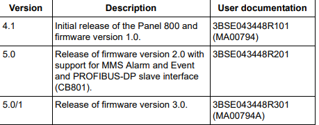
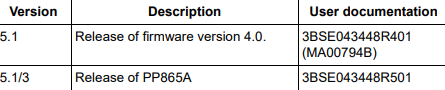
The release history of the Panel 800 is presented below.
Warning, Caution, Information, and Tip Icons
This publication includes Warning, Caution, and Information where appropriate
to point out safety related or other important information. It also includes Tip to
point out useful hints to the reader. The corresponding symbols should be
interpreted as follows:
Although Warning hazards are related to personal injury, and Caution hazards are
associated with equipment or property damage, it should be understood that
operation of damaged equipment could, under certain operational conditions, result
in degraded process performance leading to personal injury or death. Therefore,
fully comply with all Warning and Caution notices.
5.1 Release of firmware version 4.0. 3BSE043448R401
(MA00794B)
5.1/3 Release of PP865A 3BSE043448R501
Electrical warning icon indicates the presence of a hazard which could result in
electrical shock.
Warning icon indicates the presence of a hazard which could result in personal
injury.
Caution icon indicates important information or warning related to the concept
discussed in the text. It might indicate the presence of a hazard which could
result in corruption of software or damage to equipment/property.
Information icon alerts the reader to pertinent facts and conditions.
Tip icon indicates advice on, for example, how to design your project or how to
use a certain function
Section 2 Safety Precautions
Both the installer and the owner and/or operator of the operator panel must read and
understand this installation manual.
UL and cUL Installation
• This equipment is suitable for use in Class I, Division 2, Groups A, B, C and D
OR non-hazardous locations only. [Combinations of equipment in your system
are subject to investigation by the local Authority Having Jurisdiction at the
time of installation].
• Maximum ambient temperature 40 °C when mounted horizontal or 50 °C when
mounted vertical.
• WARNING – EXPLOSION HAZARD – Do not disconnect equipment unless
power has been removed or the area is known to be non-hazardous.
• For Canada also AVERTISSEMENT – RISQUE D’EXPLOSION – AVANT
-
 Beckhoff CX5130-0160 CPU module
-
Beckhoff CX5130-0155 CPU module
-
 Beckhoff CX5130-0150 CPU module
-
Beckhoff CX5130-0143 CPU module
-
 Beckhoff CX5130-0142 CPU module
-
Beckhoff CX5130-0140 CPU module
-
Beckhoff CX5130-0135 CPU module
-
Beckhoff CX5130-0130 CPU module
-
Beckhoff CX5130-0125 CPU module
-
 Beckhoff CX5130-0123 CPU module
-
Beckhoff CX5130-0122 CPU module
-
Beckhoff CX5130-0121 CPU module
-
 Beckhoff CX5130-0115 CPU module
-
Beckhoff CX5130-0113 CPU module
-
Beckhoff CX5130-0112 CPU module
-
Beckhoff CX5130-0111 CPU module
-
Beckhoff CX5130-0110 CPU module, Microsoft Windows Embedded Compact 7. no TwinCAT
-
Beckhoff CX5130-0100 CPU module, no operating system, no TwinCAT
-
 DEIF FAS-113DG Synchronisation & circuit breaker closing
-
 DEIF FAS-115DG Synchronisation & circuit breaker closing
-
 DEIF HAS-111DG Synchronisation & circuit breaker closing
-
 DEIF LSU-122DG Load sharing, paralleling & operation
-
 DEIF LSU-114DG Load sharing, paralleling & operation
-
 DEIF LSU-113DG Load sharing, paralleling & operation
-
 DEIF LSU-112DG Load sharing, paralleling & operation
-
 DEIF RMF-112D Frequency relay
-
 DEIF RMC-142D Current relay
-
 DEIF RMC-132D Current relay
-
 DEIF RMC-131D Current relay
-
 DEIF RMC-122D Current relay
-
 DEIF RMC-121D Current relay
-
 DEIF RMC-111D Current relay
-
 DEIF MVR-V211 Busbar Protection
-
 DEIF MVR-T257 Transformer Differential Protection
-
 DEIF MVR-T256 Transformer Differential Protection
-
 DEIF MVR-T216 Transformer Differential Protection
-
DEIF MVR-T215 Transformer Protection
-
 DEIF MVR-M257 Motor Differential Protection
-
 DEIF MVR-M255 Motor Protection
-
 DEIF MVR-M215 Motor Protection
-
 DEIF MVR-M210 Motor Protection
-
 DEIF MVR-G257 Generator Differential Protection
-
 DEIF MVR-G215 Generator Protection
-
 DEIF MVR-F255 Directional Feeder Protection
-
 DEIF MVR-F215 Directional Feeder Protection
-
DEIF MVR-F210 Feeder Protection
-
 DEIF MVR-F205 Directional Feeder Protection
-
 DEIF MVR-F201 Basic Feeder Protection
-
DEIF MVR-200 series Medium Voltage Relay
-
 DEIF MDR-2 Multi-differential relay
-
 DEIF LMR-122D Loss of mains relay
-
 DEIF LMR-111D Loss of mains relay
-
 DEIF APU-4 Advanced G59 and G99 protection unit
-
 DEIF iE 650 PLC - The most robust programmable automation controller available
-
 DEIF iE 350 PLC - Programmable Automation PLC Controller
-
 DEIF iE 250 PLC Versatile and modular intelligent energy PLC controller
-
 DEIF PPM-3 EDG Protection and Power Management
-
 DEIF AGC 3X 4198000234E AUTOMATIC GENSET CONTROLLER
-
 SAUTER ASF123 Damper actuator with spring return
-
SAUTER ASF122 Damper actuator with spring return
-
SAUTER ASF113F122 Damper actuator with spring return
-
SAUTER ASF113F120 Damper actuator with spring return
-
SAUTER ASF112F122 Damper actuator with spring return
-
SAUTER ASF112F120 Damper actuator with spring return
-
 SAUTER ASM 124/134 series - ASM134F130 Damper actuator
-
SAUTER ASM 134 series - ASM134SF132 Damper actuator
-
SAUTER ASM 124/134 series - ASM124SF132 Damper actuator
-
SAUTER ASM 124/134 series - ASM124F122 Damper actuator
-
SAUTER ASM 124/134 series - ASM124F120 Damper actuator
-
 SAUTER Valve actuator ASM 105S/115S series ASM115SF152
-
SAUTER Valve actuator ASM 105S/115S series ASM105SF152
-
SAUTER Valve actuator ASM 105S/115S series ASM115SF132
-
SAUTER Valve actuator ASM 105/115 series ASM105SF132
-
 SAUTER Valve actuator ASM 105/115 series ASM115F122
-
SAUTER Valve actuator ASM 105/115 series ASM115F120
-
SAUTER Valve actuator ASM 105/115 series ASM105F122
-
SAUTER Valve actuator ASM 105/115 series ASM105F120
-
SAUTER Valve actuator ASM 105/115 series ASM105F10
-
 SAUTER AKF113S Rotating actuator AKF 112/113 series
-
SAUTER AKF113F122 Rotating actuator AKF 112/113 series
-
SAUTER AKF113F120 Rotating actuator AKF 112/113 series
-
SAUTER AKF112F122 Rotating actuator AKF 112/113 series
-
SAUTER AKF112F120 Rotating actuator AKF 112/113 series
-
 SAUTER AKM115SAF332: Smart Actuator for ball valve, BACnet/IP
-
 SAUTER AKM115SAF232 Rotating Actuator AKM 115SA Smart Actuator
-
 SAUTER AKM115SF152 Rotating Actuator AKM 105S/115S Series
-
SAUTER AKM115SF132 Rotating Actuator AKM 105S/115S Series
-
SAUTER AKM105SF132 Rotating Actuator AKM 105S/115S Series
-
 SAUTER AKM115F122 Rotating actuator AKM 105/115 series
-
 SAUTER Rotating actuator AKM 105/115 series AKM115F120
-
SAUTER Rotating actuator AKM 105/115 series AKM105F122
-
SAUTER Rotating actuator AKM 105/115 series AKM105F120
-
 SAUTER Continuous actuator for unit valves, with stroke AXS215S
-
 SAUTER Linear valve actuator AXT/AXS series AXT211
-
SAUTER Linear valve actuator AXT/AXS series AXT201
-
 SAUTER Linear valve actuator AXM/AXF series AXF217S
-
SAUTER Linear valve actuator AXM/AXF series AXM217S
-
SAUTER AXM217SF404 is an electric actuator for unit valves.
-
SAUTER AXM217SF402 is an electric actuator for unit valves.
-
SAUTER Linear valve actuator AXM/AXF series AXM217
-
 SAUTER Linear valve actuator AVF 124/125 series AVF125S
-
SAUTER Linear valve actuator AVF 124/125 series AVF124S
-
SAUTER Linear valve actuator AVF 124/125 series AVF124S
-
 SAUTER AVM322S-R Linear valve actuator AVM 234S series
-
SAUTER AVM322-R Linear valve actuator AVM 234S series
-
SAUTER AVM322SF132 Linear valve actuator AVM 234S series
-
 SAUTER AVM321SF132 Linear Valve Actuator
-
 GE Power Conversion P112-6053 Advanced Micro Controller (AMC2)
-
GE Power Conversion P111-6053 Advanced Micro Controller (AMC2)
-
 GE Power Conversion P110-6053 Advanced Micro Controller (AMC2)
-
 GE Power Conversion P122-6052 Advanced Micro Controller (AMC2)
-
GE Power Conversion P121-6052 Advanced Micro Controller (AMC2)
-
 GE Power Conversion P112-6152 Advanced Micro Controller (AMC2)
-
GE Power Conversion P110-6152 Advanced Micro Controller (AMC2)
-
GE Power Conversion P112-6052 Advanced Micro Controller (AMC2)
-
GE P106-6052 AMC2 Advanced Micro Controller Unit
-
SAUTER AVF234SF232 Linear valve actuator AVM 234S series
-
SAUTER AVF234SF132 Linear valve actuator AVM 234S series
-
 SAUTER Linear valve actuator AVM 234S series AVM234SF132-6
-
SAUTER Linear valve actuator AVM 234S series AVM234SF132-5
-
SAUTER Linear valve actuator AVM 234S series AVM234SF132
-
SAUTER Linear valve actuator AVM215SF132-7
-
SAUTER Linear valve actuator AVM215SF132R
-
 Linear valve actuator AVM 115SA Smart Actuator AVM115SAF332
-
Linear valve actuator AVM 115SA Smart Actuator AVM115SAF232
-
 SAUTER Linear valve actuator AVM 105S/115S series AVM115SF132
-
SAUTER Linear valve actuator AVM 105S/115S series AVM105SF132
-
 SAUTER AVM115F901 Linear Valve Actuator