
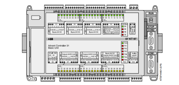
ABBAdvant Controller 31 Intelligent Decentralized Automation System
Basic Unit 07 KT 97
Basic unit with max. 480 kB user program
+ 256 kB user data, CS31 system bus
Fig. 2.1-1: Basic unit 07 KT 97 R0200
The basic unit 07 KT 97 R200 is the standard device for all applications. In addition, there are basic units with reduced
performance (e.g. 07 KT 95 or 07 KT 96) as well as ones with extended performance (e.g. 07 KT 97 R260 with
ARCNET connection, 07 KT 97 R0220 with PROFIBUS connection and 07 KT 97 R0262 with both ARCNET and
PROFIBUS connection). A comparison table is given on page 3. This document describes the basic unit 07 KT 97
R200 and then adds the data sheets of the other devices which only show the differences
2.1.1 Brief description
The basic unit 07 KT 97 works either as
· bus master in the decentralized automation system
Advant Controller 31 or as
· slave (remote processor) in the decentralized automation system Advant Controller 31 or as
· stand-alone basic unit.
The basic unit is powered by 24 V DC.
2.1.1.1 Main features
· 24 digital inputs with LED displays
· 16 digital transistor outputs with LED displays
· 8 digital inputs/outputs with LED displays
· 8 individually configurable analog inputs 0...10 V,
0...5 V, ±10 V, ±5 V, 0...20 mA, 4...20 mA, differential
inputs, Pt100 (2-wire or 3-wire), the analog inputs are
also individually configurable as digital inputs
· 4 individually configurable analog outputs ±10 V,
0...20 mA, 4...20 mA
· 2 counters for counting frequencies up to 50 kHz, configurable in 7 different operating modes
· 1 CS31 system bus interface for system expansion
· 1 interface for connecting communication modules
(e.g. 07 KP 90)
· 2 serial interfaces COM1, COM2
– as MODBUS interfaces and
– for programming and test functions
· Real-time clock
· LEDs for displaying operating conditions and error
messages
· Detachable screw-type terminal blocks
· Fastening by screws or by snapping the device onto a
DIN rail
· The lithium battery 07 LE 90 can be put into the
battery compartment in order to
– store and backup the user program in the RAM
– store and backup data which is additionally contained in the RAM, e.g. the status of flags
– backup the time and date (real-time clock)
· RUN/STOP switch for starting and aborting the program execution
· Extensive diagnosis functions
– self-diagnosis of the basic unit
– diagnosis of the CS31 system bus and the
connected modules
· Integrated Flash EPROM for storing program and data
· Exchangeable SmartMedia Card 07 MC 90 for user
data or for updating the operating system or PLC program
2.1.1.2 Project planning / start-up
The following has to be observed for project planning and
start-up:
· Programming
is performed with AC31 programming software, which
can be run on commercially available IBM compatible
PCs (see documentation of the programming system
907 AC 1131).
· Online program modification
A quick modification of the user program is possible
without interrupting the operation (see programming
system 907 AC 1131).
· Possible operating modes
– Stand-alone basic unit
– Bus master basic unit
– Slave basic unit
· Backup of data areas,
i.e. saving of data during power OFF/ON, is possible
with an integrated battery and/or
by storing them in the Flash EPROM
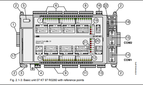
(1) Fastening the device on DIN rail
(2) Fastening the device by screws
(3) Faston earthing terminal 6.3 mm
(4) Supply voltage connection 24 V DC
(5) Battery compartment
(6) 24 digital inputs in 3 groups
(7) 24 green LEDs for the digital inputs
(8) 8 individually configurable analog inputs in
one group 0...10 V, 0...5 V, ±10 V, ±5 V,
0...20 mA, 4...20 mA, Pt100 (2-wire or 3-wire),
differential inputs, the analog inputs are
also individually configurable as digital inputs
(9) 16 digital transistor outputs in two groups
(10) 16 yellow LEDs for the digital outputs
(11) 8 digital inputs/outputs in one group
(12) 8 yellow LEDs for the digital inputs/outputs
(13) 4 individually configurable analog outputs
±10 V, 0...20 mA, 4...20 mA in one group
(14) Serial interface COM1 (programming, MMC)
(15) Serial interface COM2 (programming, MMC)
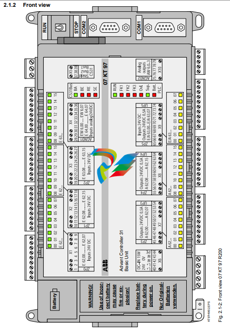
2.1.3 Structure of the front panel
Fig. 2.1-3: Basic unit 07 KT 97 R0260 with reference points
KT97HW03.EPS
(16) Connection for CS31 system bus
(17) Cover of the interface for the connection of communication modules (may only be removed for
connecting communication modules)
(18) Switch for RUN/STOP operation:
With the RUN/STOP switch the execution of the
user program is started or stopped.
(19) LED displays for CS31 system bus
BA LED green Bus active
BE LED red Bus error
RE LED red Remote unit error
SE LED red Serial unit error
(20) LED displays for RUN and error class
RUN LED green User progr. is running
FK1 LED red Fatal error
FK2 LED red Serious error
FK3 LED red Light error
(21) Other LED displays
Over- LED red Overload/short-circuit
load at an output
Supply LED green Supply voltage
available
Battery LED red Batt. not effective
(22) Insertable SmartMedia Card 07 MC 90 for
operatingsystem, user program and user data
-
 Hirschmann RS20-1600M2T1SDAEHH03.1.02 Rail Switch
 -
 Hirschmann BRS30-24TX Industrial Rail Switch
 -
 Hirschmann RSPM20-4T14T1EV9HHS999.9.99 Managed Ethernet Switch
 -
 Hirschmann BELDEN RS40-0009CCCCSDAPHH09.0.14 / RS400009CCCCSDAPHH09014
 -
Hirschmann RS40 Rail Switch RS40-0009CCCCSDAE
-
 Hirschmann BELDEN RS30-0802T1T1SDAP / RS300802T1T1SDAP Fully Managed Layer 2 Compact Rail Switch
 -
 Hirschmann BELDEN RS20-0800M2M2SDAUHH / RS200800M2M2SDAUHH
 -
 Hirschmann EAGLE30-04022O6TT999SCCY9HSE3F Industrial Firewall Router Switch
 -
 Hirschmann RS20-1600T1T1SDAEHH09.0.14 RS20 Rail Mount Ethernet Switch
 -
 Hirschmann EAGLE0200T1T1TDDY90000HHE05.3.03 Industrial Security Router
 -
Hirschmann - BELDEN MIPP-AD-1L9P
-
 HIRSCHMANN RSPM20-4Z64Z6TV9HHS9 942 106-999 RAIL SAFETY SWITCH
 -
 HIRSCHMANN FIBEROPTIC MODULE FIP P/N: OZDFIPG3T
 -
 HIRSCHMANN RS20-1600M2M2SDAUHH Ethernet rack-mounted switch
 -
 HIRSCHMANN BELDEN RS20-0400T1T1SDAEHH04.0.01 / RS200400T1T1SDAEHH04001
 -
HIRSCHMANN MM2-4FXM3 MICE Media Module
-
HIRSCHMANN RS20-0800M2M2SDAE Industrial Ethernet Rail Switch
-
 Hirschmann RS20-2400T1T1SDAP / RS20-2400T1T1SDAPHH05.0.02
 -
 GE MLJ1005B010H00C MLJ Digital Synchromism Check
 -
 ALSTOM MICROTECH DX21-M2 Digital Excitation Controller
 -
HIRSCHMANN BRS20-1200ZZZZ-STCY99HHSES
-
 HIRSCHMANN MM3-4FXM2 MICE Media Module
 -
Hirschmann RSB20-0800T1T1SAABHH 8Port ENet Rail Switch RSB20
-
 Hirschmann MACH102-8TP Ethernet Switch
 -
 SAACKE DDZ-M marine steam pressure atomizer
 -
 SAACKE SKV-A marine rotary cup atomizer
 -
 SAACKE Seavis HMI05e
 -
 Kollmorgen MMC-SD-2.0-230 Servo Drive 100-240VAC 2KW 10A Output 3PH 100-240VAC
 -
 Kollmorgen Servo drive CR10550
 -
 Kollmorgen AKD-P01207-NACN-0054 Servo Driver
 -
 Kollmorgen S406M-CA-036 Servostar
 -
.png) Kollmorgen AKD-B02407-NAAN-0000 Digital Servo Drive
Kollmorgen AKD-B02407-NAAN-0000 Digital Servo Drive -
 Kollmorgen SERVOSTAR S406AM-CA Digital Servo Drive
 -
 KOLLMORGEN SERVOSTAR 603-AS SERVO AMPLIFIER_SERVOSTAR603AS_S60301
 -
Kollmorgen S700 Servo Controller (S70602-NANANA-NA)
-
 Kollmorgen MPK411 controller
 -
 KOLLMORGEN MMC-SD-1.3-460-D Smart Drive
 -
 KOLLMORGEN AKM21C-CKB2AA-00 / AKM21CCKB2AA00 Servomotor
 -
 BECKHOFF AX5106-0000-0200 | Digital Compact Servo Drives 1-channel
 -
 BECKHOFF C3620-0000 INDUSTRIAL COMPUTER (MOTORSHELVES)
 -
 Beckhoff EK1960-0000 TwinSAFE Compact Controller
 -
 Beckhoff C6930-0050 Control Cabinet Industrial PC
 -
 Beckhoff CP7711-0001-0030 Industrial Computer Detection
 -
 Beckhoff CX1001-0111 Embedded PC CPU Module
 -
 Beckhoff C6017-0020 | Ultra-compact Industrial PC
 -
 Beckhoff EK1322 | 2-port EtherCAT P junction with feed-in
 -
 Beckhoff CP2219-0010 Panel
 -
 BECKHOFF C6015-0020 ULTRA COMPACT INDUSTRIAL PC
 -
 BECKHOFF CX2030-0120/Standard CPU Module Embedded PC Windows PLC controller
 -
 Beckhoff CP7721-1090-0020 Panel PC
 -
 Beckhoff PC CPU Module CX5130-0175
 -
 Beckhoff C6920-0050 Control Cabinet
 -
 Beckhoff EL6631 EtherCAT 2-Port Communication Interface, Profinet RT Controller
 -
 Beckhoff CP6202-0001-0060 touch screen panel PC
 -
 Beckhoff CP3916-1002-0000 Multi-Touch Control Panel
 -
 Beckhoff EP1809-0021 | EtherCAT Box, 16-channel digital input, 24 V DC, 3 ms, M8Preferred type
 -
 Beckhoff CX8190 PLC Embedded Industrial PC Ethernet Controller
 -
 Beckhoff CX2100-0914 Power Supply for External
 -
 Beckhoff Automation CP6906-0001-0000 HMI
 -
 Beckhoff EP7342-0002 Module
 -
 Beckhoff CX1020-0112 / CX1100-0910 / CX1020-N010 / CX1100-0003 Windows CPU
 -
 Beckhoff EP7211-0034 EtherCAT Box 1 Channel Motion Interface
 -
 Beckhoff C6240-0030 Control cabinet Industrial PC
 -
 beckhoff motherboard CB1052-0004 CB1052-0004
 -
 Beckhoff AX2006-AS Servo Drive / Variable Frequency Drive
 -
BECKHOFF CP6207-0001-0020 NSMP
-
 Beckhoff C6930-1142-0060 Industrial Computer
 -
 Beckhoff FC7501-0000 interface card
 -
 Beckhoff CX5140-0175 Embedded PC PLC CPU CX5140 Industrial Controller
 -
 Beckhoff CP7802-1100-0010: High-End IP65 Control Panel with DVI/USB Extended Interface
 -
BECKHOFF CP3716-1058-0010 CONTROL PANEL
-
 Beckhoff AX8108-0000 Single-Axis Module
 -
 Beckhoff CU8851-0000 | USB extension, USB Extended 2.0 receiver box
 -
Beckhoff C6017-0030 | Ultra-compact Industrial PC
-
 Beckhoff CX1001-0120/CX10010120.cx1000-n001.cx1000-n000 System Overview
 -
 Beckhoff CPU Module CX5140-0155/4GB CPU Module
 -
 Beckhoff CP6533-0001-005: Built-in Panel PC with High-Definition Multi-Touch Control
 -
 Beckhoff EL5042 | EtherCAT Terminal, 2-channel encoder interface, BiSS® C
 -
 Beckhoff C6920-1080-0040: Premium Control Cabinet Industrial PC
 -
 Beckhoff C6920-0060 | Control cabinet Industrial PC
 -
 Beckhoff Embedded-PC CX5010-1121
 -
 Beckhoff CB3050-0010 Mainboard Motherboard
 -
 Beckhoff PLC module CX1020-0000 Basic CPU module (service phase)
 -
 Beckhoff CP7812-1056-0010 15" Multitouch Display Control Panel
 -
 Beckhoff CX5120-0115 /2GB Controller Module
 -
 Beckhoff CP7201-1000-0000 Industrial Panel PC
 -
 Beckhoff Servo Motor AM8061-0JH1-0000
 -
 BECKHOFF CP6503-0001-0050 Built-in Panel PC
 -
Beckhoff CP3919-0010 Display G190ETN01.2 19" PCT V04. Multi-touch Control Panel
-
 Beckhoff CX5110-0112-9020/000368201 Embedded PC Intel Atom Processor
 -
 Beckhoff AX8206-0000 Dual-Axis Module
 -
Beckhoff Nail Operating Terminal CP7032-1031-0010
-
Beckhoff AM8042-0EH1-0000 Servomotor 4.10 Nm (M0), F4 (87 mm)
-
 Beckhoff EK9300 Beckhoff CPU Module
 -
Beckhoff CP3224-0020 Multitouch-Panel-PC
-
 Beckhoff CP2712-0000 12.1" 24VDC Touch Screen WMD0
 -
 BECKHOFF CX5240-0195 / 0000289234 Embedded PC 40 GB CFast Card
 -
 Beckhoff CP6932-1000-0000 Control Panel
 -
 BECKHOFF CX5120-0121 PLC Module
 -
 Beckhoff EL3218 | EtherCAT Terminal, 8-channel analog input
 -
Beckhoff C6640-0050 | Control cabinet Industrial PC
-
 Beckhoff Cx5130-0120/4GB Embedded-PC
 -
 BECKHOFF CX2030-0122 PLC PROCESSOR
 -
 BECKHOFF CX5020-0122 Controller Module
 -
 Beckhoff CP3915-0000 Multitouch Panel
 -
 BECKHOFF EL3014 | EtherCAT Terminal
 -
 BECKHOFF Industrial Computer c6920-1057-0030
 -
 Beckhoff CX5130-0141/4GB CX5130-0141 Embedded PC
 -
 Beckhoff C6240-1052-0040 4-086-06-3073 Industrial Computer
 -
 Beckhoff CX5140-0135 /4GB High-Performance Embedded Industrial PC
 -
 Beckhoff C6515-1001-0000 Industrial PC
 -
 Beckhoff AX5103-0000-0200 - Digital Compact Servo Drives
 -
 Beckhoff CX2030-0130-1003/4GB Basic CPU module
 -
 Beckhoff AX8620-0000 Power Supply Module
 -
 Beckhoff CX9020-0111 module with
 -
 Beckhoff EL7332 PLC Module
 -
 BECKHOFF CP7709-0001-0020 HMI
 -
 Beckhoff CX5120-0155/2GB Embedded PC
 -
 BECKHOFF CP7037-1037-0010 OPERATOR INTERFACE TOUCHSCREEN
 -
 Beckhoff EK9000 | ModbusTCP/UDP Bus Coupler
 -
 Beckhoff Touch Panel Screen CP6020 -0000-0000
 -
 Beckhoff CX2020-0121 Module FAST Shipping
 -
 Beckhoff CX2030-0125 Basic CPU Module
 -
 Beckhoff CP3918-0000 Multi-Touch 18.5" Control Panel
 -
 Automotion LC4A00010 DC BL Motor Control, ATS, Sub Assy, SCP, 115VAC,
 -
 500T-115VAC - VAS ENGINEERING - DORIC 500 SERIES DIGITAL TEMP INDICATOR
 -
 Honeywell X-DCS2000/EN Digital Integrated System Manager 50/60Hz 100-240V #4
 -
 Kollmorgen S60600 Servostar600 606-Fan 4 kVA, 6 A, 3 X 230 - 480 V


