
ABB Procontic CS 31 Intelligent decentralized automation system
This technical documentation supplied in a loose-leaf file can be easily up-dated.
In order to be registered in our revision and up-dating service, the enclosed Original Registration Form(1) should be
filled-in and addressed to your local ABB contact engineer.
The supplements contain either new sections of the documentation or replacement pages for existing sections.
Instructions for these supplements are enclosed in the corresponding parcel.
All rights reserved to change design, size, weight of the equipment described in our documentation.
Dear Sirs,
I want to keep my technical documentation updated, which is why I would like to
have my name to your list for distribution of revised documentation. The returned
original reply card contains all relevant information.
I am interested in detailled information about modifications on existing devices as
well as technical details of novel devices forming part of the control system used in
my installation.
ABB CS31
Intelligent decentralized
automation system
General
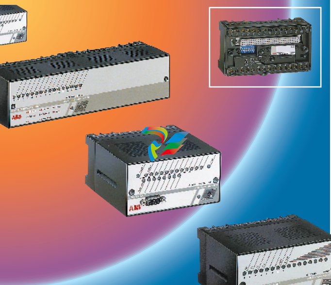
Machines and plant equipment, for
reasons of competitiveness are becoming even more
complex, the amount of information required from sensors
and actuating devices is constantly expanding, causing
heavier implementation and higher wiring costs.
The ABB Procontic CS 31 is designed to simplify
implementation and wiring.
The CS 31 is a decentralized automation system.
The system is ideally suited to applications where
modularity and cost reduction are key factors.
The CS 31 system comprises of the following :
– a central unit, enclosed within a compact case which
can be screw or DIN rail mounted,
– remote input/output plug-in units, wich are easily
removeable. The plug-in base can be screw or DIN
rail mounted,
– a simple twisted pair wire arrangement (RS 485),
which is utilized for connection of the central unit to
the I/O units.
The decentralized architecture of the ABB
Procontic CS 31 system offers a superior solution to
control system requirements:
– The central unit can be mounted within the control
panel.
– The input/output units can be mounted local to the
sensors and actuators.
As an example the central unit may be connected to
remote units distributed along a process line.
A cost reduction in wiring is possible upto 80% with the
implementation of the CS 31 system.
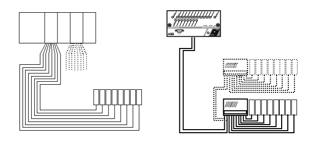
2.1 CS 31 benefits
– decentralized architecture as opposed to centralized
system,
– reduction of wiring costs (design, materials and
commissioning time),
– configurable input/output units,
– extensive diagnosis functions,
– freely expandable network. Additional units can be
connected whilst the installation is operational,
– simple transparent programming. All remote I/O channels
are handled as though they were centralized,
– remote I/O facility is integral feature and not an additional
unit,
– programmable serial communications (RS 232)
connection to modem, printer, operator display etc...
2.2 Modular system
The comprehensive range of units enhances the modularity
of the system.
For example :
The low profile 16 channel user configurable input/output
unit can be mounted on the control panel door, with inputs
and outputs connected to pushbuttons and pilot lamps.
2.3 Versatile range
The CS 31 is based upon two types of central units,
07 KR 91, 07 KT 92/07 KT 93 and 07 KR 31/07 KT 31.
The system can be configured to comply with most control
system requirements (See previous configuration
examples).
● 07 KR 91, 07 KT 92/07 KT 93 is designed for complex
applications with an higher level of functionality (Data
manipulation, PID regulation, etc...).
● 07 KR 31/07 KT 31 incorporates all of the functions
required for smaller decentralized applications, thus
providing an excellent Price/Performance ratio.
2.4 Diagnosis
The CS 31 system incorporates extensive diagnosis
functions.
All of the remote units contain a microprocessor which is
dedicated to the management of inputs/outputs and
diagnosis facilities.
The diagnosis are accessed using the "test" button on the
front of each remote unit, the results are displayed on the
I/O status led's.
The diagnosis results can be incorporated with the user
program thus enabling effective fault management.
2.5 Use of the CS 31 system
All of the remote units are easily interchangeable, even
with the process in operation, as they are plug-in base
mounted.
The screw terminals of the plug-in bases are used for
connection to the process inputs and outputs.
Bases are screw or DIN rail mounted.
The DIL switches on the bases are used for coding the
address of units.
Any additional connected units are automatically
recognized by the central unit.
NOTE : The system may comprise of remote units of
varying supply and input voltages.
2.6 Emergency operation
A system may comprise of many central units, however
one single master and the remainders slaves.
If the bus communication is interrupted or the master unit
fails the individual slave units continue with their own
operation.
2.8 General characteristics
The CS 31 system is developped according to the international standard IEC 1131-2.
● Operating conditions
– Temperature :
● operation 0 °C ... + 55 °C 32 ... 131 °F
● storage - 40 °C ... + 75 °C - 40 ... 167 °F
● transport - 25 °C ... + 75 °C - 13 ... 167 °F
– Humidity acc. to DIN 40040 class F without
condensation :
● average over the year 75 %
● up to 30 days of a year 95 %
● on the other days withregard to the average of the
year, occasionnally 85 %
– Air pressure :
● operation 800 hPA ( 2000 m)
● storage 660 hPA ( 3500 m)
● Mechanical data
– degree of
protection IP 20
– housing UL94 V0
UL94 V1 for central units serie 90,
coupler 07KPxx and units ICDxx
– vibration each of three mutually
perpendicular axes 10 Hz ...57 Hz
continuous : 0.0375 mm amplitude
occasional : 0.075 mm amplitude
57 Hz ... 150 Hz
continuous : 0.5 g acceleration
occasional : 1.0 g acceleration
– shocks occasional excursion to 15 g, 11 ms,
halfsine in each of three mutually
perpendicular axes
– impact for units with a power supply > 30 VAC.
withstand According to IEC 950 : a steel sphere
test with a mass of 500 g is to fall freely
from a height of 1300 mm
● Mounting
– DIN rail 35 mm
– Screw screws Ø 4 mm (M4)
mounting
● Serial interfaces
– for connection of the RS485,
central unit to using screw terminals
the remote units
– for programming and RS232-C
setting parameter 9 pole D connector
(female)
● Termination
– on the plug-in base ECZ use 60 °C copper conductor only
Cross section :
– bus wiring terminal : twisted pair
AWG 24 (0.22 mm2
) to AWG 18 (0.8 mm2
)
– earth terminal : rigid or stranded connector
AWG 10 (5.2 mm2
)
– Others terminals :
● inputs : stranded connector
AWG 18 (0.8 mm2
) to AWG 14 (2.1 mm2
)
● outputs : stranded connector
AWG 14 (2.1 mm2
)
● power supply
AWG 14 (2.1 mm2
)
– on removable terminal 2.5 mm2 (copper N°
AWG14)
block (small section)
– on removable terminal 1.5 mm2 (copper N°
AWG16)
block (small section)
– screws tightening 7 ibs. inch (0.8 Nm)
torque (for guidance only)
● Supply connections
– 24 VDC (process and 24 VDC
power supply (-20 %, +25 %, i.e. 19.2 ... 30V)
incl. ripple
ripple factor < 5 %
– 120 VAC power supply 120 VAC
(-15%, +10%, i.e. 102 ... 132V)
50 Hz or 60 Hz (± 5 %)
– 230 VAC power supply 230 VAC
(-15%, +10%, i.e. 195.5 ... 253V)
50 Hz or 60 Hz (± 5 %)
● Voltage drops and interruptions
– DC power supply interruption time 10 ms
time interval between two
drops 1s
– AC power supply interruption time 0.5 period
time interval between two
drops 1s
● Creepage distances and clearances
according to EN 61131-2 /
IEC1131-2
● Insulation test voltages
the insulation test voltages
are according to IEC 1131-2
● Electromagnetic compatibility (EMC)
– electrostatic discharge (ESD) according to
IEC 1000-4-2
(severity level 3)
test peak voltage :
● at discharge thru air 8 kV
● at discharge
thru relay's contact 6 kV
time between two discharges > 1s
number of discharges on each
selected point 10
– radiated electromagnetic
field immunity test according to
IEC 1000-4-3
field strength 10 V/m
(severity level 3)
frequency range 27 MHz to 1000 MHz
sweep speed 1.5 x 10E-3
decade/s
– fast transient burst test (FTT) according to
IEC 1000-4-4
interference voltage for :
mains terminals 115/230 V 2 kV
mains terminals 24 V 2 kV
output terminals 24 V 1 kV
output terminals 115/230 V 2 kV
input terminals 24 V 1 kV
input terminals 115/230 V 2 kV
analogue input/output terminals 1 kV
CS 31 bus 2 kV
programming interface 0.5 kV
– surge immunity according to
IEC 1000-4-5
test voltage for
assymetric coupling common mode
power supply (115/230 VAC) 2 kV
power supply (24 VDC) 1 kV
digital inputs/outputs 1 kV
test voltage for
symetric coupling differential mode
power supply (115/230 VAC) 1 kV
power supply (24 VDC) 1 kV
digital inputs/outputs 1 kV
● ABB Procontic CS 31 system bus
The CS 31 bus is a shield twisted pair RS485
– cross 0.22 ... 0.8 mm2
(N°
AWG 24 ... N°
AWG 18)
– twists > 10 per metre
– resistance 100 /km
-
 Hirschmann RS20-1600M2T1SDAEHH03.1.02 Rail Switch
 -
 Hirschmann BRS30-24TX Industrial Rail Switch
 -
 Hirschmann RSPM20-4T14T1EV9HHS999.9.99 Managed Ethernet Switch
 -
 Hirschmann BELDEN RS40-0009CCCCSDAPHH09.0.14 / RS400009CCCCSDAPHH09014
 -
Hirschmann RS40 Rail Switch RS40-0009CCCCSDAE
-
 Hirschmann BELDEN RS30-0802T1T1SDAP / RS300802T1T1SDAP Fully Managed Layer 2 Compact Rail Switch
 -
 Hirschmann BELDEN RS20-0800M2M2SDAUHH / RS200800M2M2SDAUHH
 -
 Hirschmann EAGLE30-04022O6TT999SCCY9HSE3F Industrial Firewall Router Switch
 -
 Hirschmann RS20-1600T1T1SDAEHH09.0.14 RS20 Rail Mount Ethernet Switch
 -
 Hirschmann EAGLE0200T1T1TDDY90000HHE05.3.03 Industrial Security Router
 -
Hirschmann - BELDEN MIPP-AD-1L9P
-
 HIRSCHMANN RSPM20-4Z64Z6TV9HHS9 942 106-999 RAIL SAFETY SWITCH
 -
 HIRSCHMANN FIBEROPTIC MODULE FIP P/N: OZDFIPG3T
 -
 HIRSCHMANN RS20-1600M2M2SDAUHH Ethernet rack-mounted switch
 -
 HIRSCHMANN BELDEN RS20-0400T1T1SDAEHH04.0.01 / RS200400T1T1SDAEHH04001
 -
HIRSCHMANN MM2-4FXM3 MICE Media Module
-
HIRSCHMANN RS20-0800M2M2SDAE Industrial Ethernet Rail Switch
-
 Hirschmann RS20-2400T1T1SDAP / RS20-2400T1T1SDAPHH05.0.02
 -
 GE MLJ1005B010H00C MLJ Digital Synchromism Check
 -
 ALSTOM MICROTECH DX21-M2 Digital Excitation Controller
 -
HIRSCHMANN BRS20-1200ZZZZ-STCY99HHSES
-
 HIRSCHMANN MM3-4FXM2 MICE Media Module
 -
Hirschmann RSB20-0800T1T1SAABHH 8Port ENet Rail Switch RSB20
-
 Hirschmann MACH102-8TP Ethernet Switch
 -
 SAACKE DDZ-M marine steam pressure atomizer
 -
 SAACKE SKV-A marine rotary cup atomizer
 -
 SAACKE Seavis HMI05e
 -
 Kollmorgen MMC-SD-2.0-230 Servo Drive 100-240VAC 2KW 10A Output 3PH 100-240VAC
 -
 Kollmorgen Servo drive CR10550
 -
 Kollmorgen AKD-P01207-NACN-0054 Servo Driver
 -
 Kollmorgen S406M-CA-036 Servostar
 -
.png) Kollmorgen AKD-B02407-NAAN-0000 Digital Servo Drive
Kollmorgen AKD-B02407-NAAN-0000 Digital Servo Drive -
 Kollmorgen SERVOSTAR S406AM-CA Digital Servo Drive
 -
 KOLLMORGEN SERVOSTAR 603-AS SERVO AMPLIFIER_SERVOSTAR603AS_S60301
 -
Kollmorgen S700 Servo Controller (S70602-NANANA-NA)
-
 Kollmorgen MPK411 controller
 -
 KOLLMORGEN MMC-SD-1.3-460-D Smart Drive
 -
 KOLLMORGEN AKM21C-CKB2AA-00 / AKM21CCKB2AA00 Servomotor
 -
 BECKHOFF AX5106-0000-0200 | Digital Compact Servo Drives 1-channel
 -
 BECKHOFF C3620-0000 INDUSTRIAL COMPUTER (MOTORSHELVES)
 -
 Beckhoff EK1960-0000 TwinSAFE Compact Controller
 -
 Beckhoff C6930-0050 Control Cabinet Industrial PC
 -
 Beckhoff CP7711-0001-0030 Industrial Computer Detection
 -
 Beckhoff CX1001-0111 Embedded PC CPU Module
 -
 Beckhoff C6017-0020 | Ultra-compact Industrial PC
 -
 Beckhoff EK1322 | 2-port EtherCAT P junction with feed-in
 -
 Beckhoff CP2219-0010 Panel
 -
 BECKHOFF C6015-0020 ULTRA COMPACT INDUSTRIAL PC
 -
 BECKHOFF CX2030-0120/Standard CPU Module Embedded PC Windows PLC controller
 -
 Beckhoff CP7721-1090-0020 Panel PC
 -
 Beckhoff PC CPU Module CX5130-0175
 -
 Beckhoff C6920-0050 Control Cabinet
 -
 Beckhoff EL6631 EtherCAT 2-Port Communication Interface, Profinet RT Controller
 -
 Beckhoff CP6202-0001-0060 touch screen panel PC
 -
 Beckhoff CP3916-1002-0000 Multi-Touch Control Panel
 -
 Beckhoff EP1809-0021 | EtherCAT Box, 16-channel digital input, 24 V DC, 3 ms, M8Preferred type
 -
 Beckhoff CX8190 PLC Embedded Industrial PC Ethernet Controller
 -
 Beckhoff CX2100-0914 Power Supply for External
 -
 Beckhoff Automation CP6906-0001-0000 HMI
 -
 Beckhoff EP7342-0002 Module
 -
 Beckhoff CX1020-0112 / CX1100-0910 / CX1020-N010 / CX1100-0003 Windows CPU
 -
 Beckhoff EP7211-0034 EtherCAT Box 1 Channel Motion Interface
 -
 Beckhoff C6240-0030 Control cabinet Industrial PC
 -
 beckhoff motherboard CB1052-0004 CB1052-0004
 -
 Beckhoff AX2006-AS Servo Drive / Variable Frequency Drive
 -
BECKHOFF CP6207-0001-0020 NSMP
-
 Beckhoff C6930-1142-0060 Industrial Computer
 -
 Beckhoff FC7501-0000 interface card
 -
 Beckhoff CX5140-0175 Embedded PC PLC CPU CX5140 Industrial Controller
 -
 Beckhoff CP7802-1100-0010: High-End IP65 Control Panel with DVI/USB Extended Interface
 -
BECKHOFF CP3716-1058-0010 CONTROL PANEL
-
 Beckhoff AX8108-0000 Single-Axis Module
 -
 Beckhoff CU8851-0000 | USB extension, USB Extended 2.0 receiver box
 -
Beckhoff C6017-0030 | Ultra-compact Industrial PC
-
 Beckhoff CX1001-0120/CX10010120.cx1000-n001.cx1000-n000 System Overview
 -
 Beckhoff CPU Module CX5140-0155/4GB CPU Module
 -
 Beckhoff CP6533-0001-005: Built-in Panel PC with High-Definition Multi-Touch Control
 -
 Beckhoff EL5042 | EtherCAT Terminal, 2-channel encoder interface, BiSS® C
 -
 Beckhoff C6920-1080-0040: Premium Control Cabinet Industrial PC
 -
 Beckhoff C6920-0060 | Control cabinet Industrial PC
 -
 Beckhoff Embedded-PC CX5010-1121
 -
 Beckhoff CB3050-0010 Mainboard Motherboard
 -
 Beckhoff PLC module CX1020-0000 Basic CPU module (service phase)
 -
 Beckhoff CP7812-1056-0010 15" Multitouch Display Control Panel
 -
 Beckhoff CX5120-0115 /2GB Controller Module
 -
 Beckhoff CP7201-1000-0000 Industrial Panel PC
 -
 Beckhoff Servo Motor AM8061-0JH1-0000
 -
 BECKHOFF CP6503-0001-0050 Built-in Panel PC
 -
Beckhoff CP3919-0010 Display G190ETN01.2 19" PCT V04. Multi-touch Control Panel
-
 Beckhoff CX5110-0112-9020/000368201 Embedded PC Intel Atom Processor
 -
 Beckhoff AX8206-0000 Dual-Axis Module
 -
Beckhoff Nail Operating Terminal CP7032-1031-0010
-
Beckhoff AM8042-0EH1-0000 Servomotor 4.10 Nm (M0), F4 (87 mm)
-
 Beckhoff EK9300 Beckhoff CPU Module
 -
Beckhoff CP3224-0020 Multitouch-Panel-PC
-
 Beckhoff CP2712-0000 12.1" 24VDC Touch Screen WMD0
 -
 BECKHOFF CX5240-0195 / 0000289234 Embedded PC 40 GB CFast Card
 -
 Beckhoff CP6932-1000-0000 Control Panel
 -
 BECKHOFF CX5120-0121 PLC Module
 -
 Beckhoff EL3218 | EtherCAT Terminal, 8-channel analog input
 -
Beckhoff C6640-0050 | Control cabinet Industrial PC
-
 Beckhoff Cx5130-0120/4GB Embedded-PC
 -
 BECKHOFF CX2030-0122 PLC PROCESSOR
 -
 BECKHOFF CX5020-0122 Controller Module
 -
 Beckhoff CP3915-0000 Multitouch Panel
 -
 BECKHOFF EL3014 | EtherCAT Terminal
 -
 BECKHOFF Industrial Computer c6920-1057-0030
 -
 Beckhoff CX5130-0141/4GB CX5130-0141 Embedded PC
 -
 Beckhoff C6240-1052-0040 4-086-06-3073 Industrial Computer
 -
 Beckhoff CX5140-0135 /4GB High-Performance Embedded Industrial PC
 -
 Beckhoff C6515-1001-0000 Industrial PC
 -
 Beckhoff AX5103-0000-0200 - Digital Compact Servo Drives
 -
 Beckhoff CX2030-0130-1003/4GB Basic CPU module
 -
 Beckhoff AX8620-0000 Power Supply Module
 -
 Beckhoff CX9020-0111 module with
 -
 Beckhoff EL7332 PLC Module
 -
 BECKHOFF CP7709-0001-0020 HMI
 -
 Beckhoff CX5120-0155/2GB Embedded PC
 -
 BECKHOFF CP7037-1037-0010 OPERATOR INTERFACE TOUCHSCREEN
 -
 Beckhoff EK9000 | ModbusTCP/UDP Bus Coupler
 -
 Beckhoff Touch Panel Screen CP6020 -0000-0000
 -
 Beckhoff CX2020-0121 Module FAST Shipping
 -
 Beckhoff CX2030-0125 Basic CPU Module
 -
 Beckhoff CP3918-0000 Multi-Touch 18.5" Control Panel
 -
 Automotion LC4A00010 DC BL Motor Control, ATS, Sub Assy, SCP, 115VAC,
 -
 500T-115VAC - VAS ENGINEERING - DORIC 500 SERIES DIGITAL TEMP INDICATOR
 -
 Honeywell X-DCS2000/EN Digital Integrated System Manager 50/60Hz 100-240V #4
 -
 Kollmorgen S60600 Servostar600 606-Fan 4 kVA, 6 A, 3 X 230 - 480 V


