ABBAO2000-LS25
Introduction
1.1 General This manual contains information of installation, operation and maintenance of the AO2000- LS25 Laser analyzer. A description of the analyzer and its basic features is also included. Please read sections 3 and 4 carefully before using the analyzer. It is a sophisticated instrument utilizing state-of-the-art electronic and laser technology. Installation and maintenance of the instrument require care and preparation. Failure to do so may damage the instrument and void the warranty.
1.2 Measuring principle The analyzer is an optical instrument for continuous in-situ gas monitoring in stack, pipes, process chambers or similar and is based on tunable diode laser absorption spectroscopy (TDLAS). The analyzer utilizes a transmitter/receiver configuration (mounted diametrically opposite each other) to measure the average gas concentration along the line-of-sight path. The measuring principle is infrared single-line absorption spectroscopy, which is based on the fact that each gas has distinct absorption lines at specific wavelengths. The measuring principle is illustrated in Figure 1-1. The laser wavelength is scanned across a chosen absorption line of the gas to be measured. The absorption line is carefully selected to avoid cross interference from other (background) gases. The detected light intensity varies as a function of the laser wavelength due to absorption of the targeted gas molecules in the optical path between transmitter and receiver. In order to increase sensitivity the wavelength modulation technique is employed: the laser wavelength is slightly modulated while scanning the absorption line. The detector signal is spectrally decomposed into frequency components at harmonics of the laser modulation frequency. The second harmonics of the signal is used to measure the concentration of the absorbing gas. The line amplitude and line width are both extracted from the second harmonics line shape, which makes the measured concentration insensitive to line shape variations (line broadening effect) caused by background gases. NOTE: The analyzer measures the concentration of only the FREE molecules of the specific gas, thus not being sensitive to the molecules bound with some other molecules into complexes and to the molecules attached to or dissolved in particles and droplets. Care should be taken when comparing the measurements with the results from other measurement techniques.
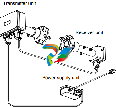
1.3 Instrument description The analyzer consists of 3 separate units (see Figure 1-2): Transmitter unit with purging
Receiver unit with purging
Power supply unit

The transmitter unit contains the laser module with a temperature stabilized diode laser, collimating optics, and the main electronics in a coated Aluminum box. The receiver unit contains a focusing lens, the photodetector and the receiver electronics in a coated Aluminum box. Both transmitter and receiver units have environmental protection IP66, and the standard optical windows withstand pressures up to 5 bar (absolute pressure). The monitor is installed by assembling the transmitter and receiver units with the supplied purging & alignment units, which in turn are mounted onto the DN50 process flanges (see Figure 3-1). The optical alignment is easy and reliable, and the purging prevents dust and other contamination from settling on the optical windows. A block diagram of AO2000-LS25 is shown in Figure 1-3. The power supply unit transforms 100-240 V AC to 24 V DC (if 24 VDC is available it can be supplied directly to the transmitter unit). The power supply box is connected to the transmitter box with a cable. The 4–20 mA input signals from external gas temperature/pressure sensors can be connected to the screw terminals inside the power box or directly to the cable connector on the transmitter unit. The receiver electronics is connected with the transmitter electronics with a cable. The detected absorption signal from the photodetector is amplified and transferred to the transmitter unit through this cable. The same cable transfers the required power from the transmitter unit to the receiver unit. The transmitter Al box contains the major part of the electronics. The CPU board performs all instrument control and calculation of the gas concentration. The main board incorporates all electronics required for instrument operation such as diode laser current and temperature control and analogue-to-digital signal conversion. A display (LCD) continuously displays the gas concentration, laser beam transmission and instrument status. The RS-232 port can be used for direct serial communication with a PC. The optional Ethernet board provides TCP/IP communication via LAN (local area network), which can be used instead of serial communication. All cable connectors are Phoenix VARIOSUB type and waterproof.
Software Software for the analyzer consists of 2 programs: 1. A program hidden to the user and integrated in the CPU electronics, running the micro controller on the CPU card. The program performs all necessary calculations and selfmonitoring tasks. 2. A Windows based program running on a standard PC connected through the RS-232 connection. The program enables communication with the instrument during installation, service and calibration. The operator will need to use the PC based program only during installation and calibration and not during normal operation of the instrument. See Section 4 for more details. 1.5 Laser classification and warnings The diode lasers used in the analyzer operate in the near infrared (NIR) range between 700 and 2400 nm depending on the gas to be measured. Laser Class 1M for sample component O2 Laser Class 1 for all other sample components according to IEC 60825-1. NOTE: The lasers emit invisible light! WARNING: Class 1M Laser Product – Do not open when energized! Do not view directly with optical instruments! WARNING: Class 1 Laser Product – Do not open when energized!


