
ABBSYSTEM DRIVES MEGADRIVE-LCI water-cooled User manual
—
LEGAL DISCLAIMER
This document contains information about one or more ABB products and may include a description of or a reference to one
or more standards that are relevant to the ABB products. The presence of any such description of a standard or reference to
a standard is not a representation that all of the ABB products referenced in this document include all the features of the
described or referenced standard. In order to determine the specific features included in a particular ABB product, the
product specifications for the particular ABB product apply.
The buyer acknowledges the proprietary and confidential nature of the information contained in this document and agrees
that all rights to and concerning the information contained in this document remain vested in ABB, in particular with regard
to any intellectual property rights. Nothing contained herein shall oblige ABB to furnish any particular information to the
buyer.
The information in this document is subject to change without notice and should not be construed as a binding declaration
of ABB. ABB assumes no responsibility for any errors or omissions in this document.
Products described or referenced in this document are designed to be connected with networks and provide information and
data through network interfaces. The products must be connected to a secure network. It is the sole responsibility of the
buyer of the products to provide and continuously ensure a secure connection between the product and the system network
and/or any other networks that may be connected to the product. ABB is in no event liable for the security of the network used
by buyer.
The buyer of the product must establish and maintain appropriate measures, including, but not limited to, the installation of
firewalls, application of authentication measures, encryption of data, installation of antivirus programs, and so on, to protect
these products, the network, its system, and interfaces against security breaches, unauthorized access, interference,
intrusion, leakage, and/or theft of data or information. Any liability of ABB in this regard is excluded.
ABB may perform functionality testing on the products and may release updates. However, it is the sole responsibility of the
buyer of the product to ensure that any product updates or other major system updates (to include but not limited to code
changes, configuration file changes, third-party software updates or patches, hardware change out, and so on) are
compatible with the security measures implemented. The buyer of the product must verify that the system and associated
products function as expected in the environment in which they are deployed. ABB has no obligations in this regard.
In no event shall ABB be liable for any damages inclusive but not limited to indirect, special, incidental or consequential
damages of any nature or kind whatsoever arising from the use of this document, nor shall ABB be liable for any damages
inclusive but not limited to indirect, special, incidental or consequential damages arising from the use of any software or
hardware described in this document.
This document and parts thereof must be kept strictly confidential and must not be reproduced or copied without the prior
written permission from ABB, and the contents thereof must not be disclosed or made available to any third party nor used
for any unauthorized purpose.
The software or hardware described in this document may be furnished under a license and may be used, copied, or disclosed
only in accordance with the terms of such license.
—
TRADEMARKS
ABB is a registered trademark of ASEA BROWN BOVERI LTD.
All rights to copyrights, registered trademarks, and trademarks reside with their respective owners.
Copyright © 2025 ABB.
All rights reserved.
1. About this manual
1.1. Equipment covered by this manual
This manual covers a standard drive and provides generic information on the drive. The manual does
not claim to cover all variations and details of the drive, nor to consider all eventualities that may
arise during installation, commissioning, operation and maintenance of the drive.
If the drive is adapted to specific customer needs or applications, and handling, installation and
operation of the drive are affected by these modifications, information on these modifications is
provided in the appropriate documentation (eg, layout drawings, wiring diagrams, technical data,
engineering notes).
If information is required beyond the instructions in this manual, refer the matter to ABB.
1.2. Terms and abbreviations
The following table lists terms and abbreviations you should be familiar with when using this user
manual. Some of the terms and abbreviations used in this user manual are unique to ABB and might
differ from the normal usage.
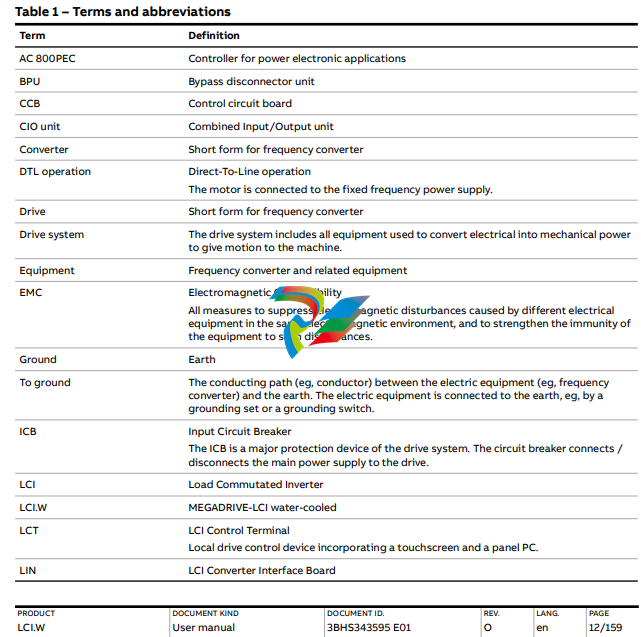
Table 1 – Terms and abbreviations (continued)
Term Definition
Line voltage RMS voltage of the main power supply of the drive
PE Protective Earth PPE Personal Protective Equipment
1.3. Structure of the user documentation
The documentation for a standard drive consists of this document and the following project-specific
appendices.
NOTE – These appendices are NOT included in this document.
– Appendix A - Technical data contains the technical data sheets of the drive.
– Appendix B - Mechanical drawings provides the outline drawings of the drive. The drawings
are generated according to the customer-specific project.
– Appendix C - Electrical drawings including parts list contains the circuit diagrams with
information on device identification, cross-reference and device identification conventions. The
diagrams are generated according to the customer-specific project. “Setting of protective
devices” is generated according to the customer-specific project. The parts list is produced for
each project and contains all information to identify a component.
– Appendix D - Signal and parameter table includes descriptions of actual signals, control and
status words, and control parameters and their default settings.
– Appendix F - Test reports and certificates provides the test reports of the drive. Quality
certificates, and codes and standards the drive complies with are added if necessary for the
project.
– Appendix G - Additional manuals / options provides manuals about additional equipment
delivered with the drive (such as project-specific options like pulse encoder or fieldbus
interfaces), or information on modifications of the standard drive.
– Appendix H - Water-cooling unit includes raw-water specification and water cooling unit user
manual.
1.4. Related documents
Line voltage RMS voltage of the main power supply of the drive
PE Protective Earth
PPE Personal Protective Equipment
1.4.1. Service documents
Title ABB ID
MEGADRIVE-LCI preventive maintenance schedule 3BHS855047 E01
Ethernet - NETA-21 remote monitoring tool user manual 3AUA0000096939
1.4.2. Specifications and guidelines
Title ABB ID
Auxiliary power and control cables guideline 3BHS813742 E01
1.5. Target groups and required qualifications
The drive presented in this manual is part of an industrial environment where voltages are present
that contain a potential hazard of electric shock and/or burn. For this reason, only personnel who
have a thorough knowledge of the drive and the industrial environment and have obtained the
required qualification must handle, install, operate, or maintain the drive.
The manual addresses personnel who are responsible for unpacking, transportation, installation,
operation and maintenance of the equipment. The personnel must carry out the below listed tasks
in a manner that does not cause physical harm or danger, and to ensure the safe and reliable
functioning of the drive.
IMPORTANT! Commissioning of drive equipment must only be performed by qualified and certified
personnel.
1.5.1. Handling
The personnel must be skilled and experienced in unpacking and transporting heavy equipment.
1.5.2. Mechanical installation
The personnel must be qualified to prepare the installation site according to the site and equipment
requirements and to perform the installation accordingly.
1.5.3. Electrical installation
The personnel must have a sound knowledge of the relevant electrical codes and specifications
covering low and medium voltage equipment, be experienced with electrical wiring principles, and
know the electrical symbols typically used in wiring diagrams.
1.5.4. Operation
The personnel include all persons who operate the equipment from the local operating panel of the
drive. The personnel must know the functions of the operating panel, be adequately trained for the
drive, and know the driven process. Special knowledge of frequency converter technology is not
required.
1.5.5. Maintenance
The personnel include all persons who:
– Are qualified to carry out preventive and corrective maintenance on the drive as described in
this manual
– Are thoroughly familiar with the drive
– Have a sound knowledge of the relevant electrical codes and specifications covering low and
medium voltage equipment
– Are able to assess the hazards associated with the energy sources of the drive system and act
correspondingly
– Know the safe shutdown and grounding procedures for the drive system
1.6. Intended use of the equipment
Those in charge of the drive must ensure that the equipment is only used as specified in the
contractual documents, operated under the conditions stipulated in the technical specifications and
on the rating plate of the drive, and serviced in the intervals as specified by ABB.
Use of the drive outside the scope of the specifications is not permitted.
Intended equipment use also implies that only spare parts recommended and approved by ABB must
be used.
Unauthorized modifications and constructional changes of the drive are not permitted.
1.7. Cyber security features
The following sections describe the cyber security features of the drive.
1.7.1. Software security
The cyber security robustness of the drive is achieved with technical solutions (security features on
the component level) as well as using the following best practices when you integrate the drive into
your system and when you interact with the drive:
– Isolate drive control network (172.16.0.0) from other networks.
– Restrict drive connections to the interfaces in Table 2.
– Scan USB flash drives for viruses/malware before you connect them to the LCT.
– Route Ethernet-based bus communication (if existing) for the plant control system through a
protected control network infrastructure that is isolated from the Internet.
– Follow the remote access gateway setup recommendations to establish a network connection
to the ABB Ability platform.
– Restrict physical access to the drive and control network access to authorized personnel.
– Only allow control network access for drive servicing by qualified personnel.
Table 2 – Drive connection interfaces
Connection type Interface
Drive control (remote) Hardwired IO or fieldbus
Data collection (local) USB ports on control terminal (LCT)
Data collection and monitoring (remote) Remote access gateway
1.7.2. PEC controller security features
The PEC controller software fulfills the minimum cyber-security requirements by using security
features of AC 800PEC platform. The following Ethernet ports are open by default to ensure that the
system operates properly.
The AC 800PEC controller is also equipped with a serial port that provides a root shell for a user to
directly change a password. This port must be secured and only made accessible to authorized
persons.
IMPORTANT! Connecting the serial port to a remote terminal server to gain access the serial port
remotely can create security risks. Exposure of the Ethernet ports, serial port or controller password
to unauthorized persons can create significant security risk.
1.7.3. Control terminal (LCT) security features
The LCT Ethernet interface (AC 800PEC) is used for the internal exchange of drive data.
The main security features of the LCT are:
– System files are write-protected
A few storage locations for user data and settings do not have write protection.
– LCT regularly reboots from write-protected system storage to restore the original state and
configuration of the LCT operating system
– Unused ports (Ethernet and others) are disabled or blocked.
Ports and services that are required by the system are left open and are described in Table 4.
Table 3 – Open Ethernet ports for PEC controller software
Port Service Usage
22/tcp ssh/sftp Secure communication with AC 800PEC controller
(used by AC 800PEC Tool, LCT, Shell Terminal)
8080 / tcp http-proxy,
gSOAP soap2.8
SOAP communication with AC 800PEC controller
8081 / tcp blackice-icecap,
gSOAP soap2.8
SOAP communication with AC 800PEC controller
102 / tcp mms/IEC61850 MMS Server (only running with Industrial IT), IEC61850
123 / udp ntp Network Time Protocol: Synchronize computer clock times in a network
of computers.
5002 / udp rfe/PEC Scanner For scanning controller over network (used by AC 800PEC Tool)
Table 4 – Opens ports for the LCT
Port Service Usage
102 / tcp MMS Communication with AC 800PEC controller
135 / tcp msrpc Windows service
139 / tcp NetBIOS-ssn Windows service
445 / tcp Microsoft-ds? Windows service
3050 / tcp Gds_db Database access
3389 / tcp ms-wbt-server Windows service
5040 / tcp CDP Windows external devices communication
7680 / tcp WUDO Windows Updates Optimization
49664 / tcp WinInit Windows startup
49665 / tcp EventLog Logging windows events
49666 / tcp Schedule Task scheduling
49667 / tcp SessionEnv Remote Desktop configuration
49668 / tcp Spooler Printer communication
49669 / tcp PolicyAgent Securing TCP/IP connections
49670 / tcp Services.exe Windows services control
49672 / tcp Vaultsvc, KeyIso, SamSS Windows credential and accounts management
137 / udp NetBIOS-ns Windows service
138 / udp NetBIOS-dgm Windows service
147 / udp iso-ip Used for automatic detection of other OPC nodes on the network
500 / udp ISAKMP Cryptographic key management
2423 / udp RNRP Routing in redundant industrial networks
3339 / udp RNRP Routing in redundant industrial networks
3389 / udp ms-wbt-server
4500 / udp NAT-T.IKE NAT traversal
5050 / udp CDP As 5040/tcp but connectionless
49665 / udp unknown Used for automatic detection of other OPC nodes on the network
1.7.4. List of software accounts
The following tables contain the login credentials.
Table 5 – Control terminal software accounts
Account description User Password
Windows user account
(local user account)
LCTuser N/A (undisclosed)
Windows account
(administrator)
LCT N/A (undisclosed)
LCT Application1
1 See 9.2.4 User passwords on page 96.
Operator Level 1 ABB1
LCT Application 1 Operator Level 2 ABB2
LCT Application 1 Operator Level 3 ABB3
LCT Application 1 Administrator N/A (undisclosed)
Table 6 – AC 800PEC, LIN-boards, and CIO-boards software accounts
Account description User Password
FTP and telnet access user N/A (undisclosed)
Table 7 – NETA-21 software account
Account description User Password
Configuration interface Admin N/A (undisclosed)
1.8. Quality certificates and applicable standards
The following certificates and conformity declarations are available with ABB:
– ISO 9001 and ISO 14001 certificates stating that ABB Switzerland Ltd has implemented and
maintains a management system that fulfills the requirements of the normative standards
Table 8 – Standards
Standard Title
ANSI Z535.6 American national standard for product safety information in product manuals, instructions, and
other collateral materials
ISO 3864-2 2004 (E) - Graphical symbols – Safety colors and safety signs – Part 2: Design principles for product
safety labels
ISO 7010 2011 (E) - Graphical symbols - Safety colours and safety signs - Registered safety sign
EN 50110 European standard code for electrical work safety
ISO 13849-1 Safety of machinery - Safety-related parts of control systems - Part 1: General principles for design,
section 6.2.6 Category 3
IEC 60204-1 Safety of machinery - Electrical equipment of machines - Part 1: General requirements
IEC 60721-3-1 Classification of environmental conditions - Part 3-1: Classification of groups of environmental
parameters and their severities - Storage
IEC 60721-3-2 Classification of environmental conditions - Part 3-2: Classification of groups of environmental
parameters and their severities - Transportation and Handling
IEC 60721-3-3 Classification of environmental conditions - Part 3: Classification of groups of environmental
parameters and their severities - Section 3: Stationary use at weather-protected locations
IEC 62477-2 Safety requirements for power electronic converter systems and equipment - Part 2: Power electronic
converters from 1 000 V AC or 1 500 V DC up to 36 kV AC or 54 kV DC
1.9. Document conventions
The document uses the following font formats and symbols. See also 2.1 Safety messages and safety
signs in this document on page 22.
Font formats
Convention Description
Prerequisite for a task
1. Sequential procedural steps in a task
▶
•
Non-sequential procedural steps in a task or items in a list
→ Instructions on how to avoid a safety hazard
1) Numbered list
(1) Explanation for callout keys in legend under an illustration or refers to a callout key in the
main text, eg, “Lift fan (1)” or “Remove cover (1, Fig. 2) and…”
Italic text Identifies software parameters, eg, 16.02 PARAMETER LOCK.
Bold text Depending on the context, indicates a safety hazard, the text that you type, a software or
physical button, or a link to another part of the document
Underlined text Identifies a hyperlink
Courier font Identifies software file names and file paths
Cursor Represents blinking text on a screen
. Important safety information
2.1. Safety messages and safety signs in this document
This document uses ANSI Z535.6 signal words, ISO 7010 safety signs, and ISO 3864-2 colors to
highlight safety-related information.
2.1.1. Safety messages
2.1.2. Safety signs
Read this material carefully before working on or around the equipment. Failure to do so
can result in serious Injury or DEATH! Keep for future reference.
This is the safety alert symbol. It is used to alert you to potential physical injury hazards.
Obey all safety messages that follow this symbol to avoid possible injury or death.
DANGER
Danger indicates a hazardous situation which, if not avoided, will result in death or
serious injury.
WARNING
Warning indicates a hazardous situation which, if not avoided, could result in death
or serious injury.
CAUTION
Caution indicates a hazardous situation which, if not avoided, could result in minor
or moderate injury.
NOTICE
Notice is used to address practices not related to physical injury, but which can
result in equipment damage
-
 Hirschmann RS20-1600M2T1SDAEHH03.1.02 Rail Switch
 -
 Hirschmann BRS30-24TX Industrial Rail Switch
 -
 Hirschmann RSPM20-4T14T1EV9HHS999.9.99 Managed Ethernet Switch
 -
 Hirschmann BELDEN RS40-0009CCCCSDAPHH09.0.14 / RS400009CCCCSDAPHH09014
 -
Hirschmann RS40 Rail Switch RS40-0009CCCCSDAE
-
 Hirschmann BELDEN RS30-0802T1T1SDAP / RS300802T1T1SDAP Fully Managed Layer 2 Compact Rail Switch
 -
 Hirschmann BELDEN RS20-0800M2M2SDAUHH / RS200800M2M2SDAUHH
 -
 Hirschmann EAGLE30-04022O6TT999SCCY9HSE3F Industrial Firewall Router Switch
 -
 Hirschmann RS20-1600T1T1SDAEHH09.0.14 RS20 Rail Mount Ethernet Switch
 -
 Hirschmann EAGLE0200T1T1TDDY90000HHE05.3.03 Industrial Security Router
 -
Hirschmann - BELDEN MIPP-AD-1L9P
-
 HIRSCHMANN RSPM20-4Z64Z6TV9HHS9 942 106-999 RAIL SAFETY SWITCH
 -
 HIRSCHMANN FIBEROPTIC MODULE FIP P/N: OZDFIPG3T
 -
 HIRSCHMANN RS20-1600M2M2SDAUHH Ethernet rack-mounted switch
 -
 HIRSCHMANN BELDEN RS20-0400T1T1SDAEHH04.0.01 / RS200400T1T1SDAEHH04001
 -
HIRSCHMANN MM2-4FXM3 MICE Media Module
-
HIRSCHMANN RS20-0800M2M2SDAE Industrial Ethernet Rail Switch
-
 Hirschmann RS20-2400T1T1SDAP / RS20-2400T1T1SDAPHH05.0.02
 -
 GE MLJ1005B010H00C MLJ Digital Synchromism Check
 -
 ALSTOM MICROTECH DX21-M2 Digital Excitation Controller
 -
HIRSCHMANN BRS20-1200ZZZZ-STCY99HHSES
-
 HIRSCHMANN MM3-4FXM2 MICE Media Module
 -
Hirschmann RSB20-0800T1T1SAABHH 8Port ENet Rail Switch RSB20
-
 Hirschmann MACH102-8TP Ethernet Switch
 -
 SAACKE DDZ-M marine steam pressure atomizer
 -
 SAACKE SKV-A marine rotary cup atomizer
 -
 SAACKE Seavis HMI05e
 -
 Kollmorgen MMC-SD-2.0-230 Servo Drive 100-240VAC 2KW 10A Output 3PH 100-240VAC
 -
 Kollmorgen Servo drive CR10550
 -
 Kollmorgen AKD-P01207-NACN-0054 Servo Driver
 -
 Kollmorgen S406M-CA-036 Servostar
 -
.png) Kollmorgen AKD-B02407-NAAN-0000 Digital Servo Drive
Kollmorgen AKD-B02407-NAAN-0000 Digital Servo Drive -
 Kollmorgen SERVOSTAR S406AM-CA Digital Servo Drive
 -
 KOLLMORGEN SERVOSTAR 603-AS SERVO AMPLIFIER_SERVOSTAR603AS_S60301
 -
Kollmorgen S700 Servo Controller (S70602-NANANA-NA)
-
 Kollmorgen MPK411 controller
 -
 KOLLMORGEN MMC-SD-1.3-460-D Smart Drive
 -
 KOLLMORGEN AKM21C-CKB2AA-00 / AKM21CCKB2AA00 Servomotor
 -
 BECKHOFF AX5106-0000-0200 | Digital Compact Servo Drives 1-channel
 -
 BECKHOFF C3620-0000 INDUSTRIAL COMPUTER (MOTORSHELVES)
 -
 Beckhoff EK1960-0000 TwinSAFE Compact Controller
 -
 Beckhoff C6930-0050 Control Cabinet Industrial PC
 -
 Beckhoff CP7711-0001-0030 Industrial Computer Detection
 -
 Beckhoff CX1001-0111 Embedded PC CPU Module
 -
 Beckhoff C6017-0020 | Ultra-compact Industrial PC
 -
 Beckhoff EK1322 | 2-port EtherCAT P junction with feed-in
 -
 Beckhoff CP2219-0010 Panel
 -
 BECKHOFF C6015-0020 ULTRA COMPACT INDUSTRIAL PC
 -
 BECKHOFF CX2030-0120/Standard CPU Module Embedded PC Windows PLC controller
 -
 Beckhoff CP7721-1090-0020 Panel PC
 -
 Beckhoff PC CPU Module CX5130-0175
 -
 Beckhoff C6920-0050 Control Cabinet
 -
 Beckhoff EL6631 EtherCAT 2-Port Communication Interface, Profinet RT Controller
 -
 Beckhoff CP6202-0001-0060 touch screen panel PC
 -
 Beckhoff CP3916-1002-0000 Multi-Touch Control Panel
 -
 Beckhoff EP1809-0021 | EtherCAT Box, 16-channel digital input, 24 V DC, 3 ms, M8Preferred type
 -
 Beckhoff CX8190 PLC Embedded Industrial PC Ethernet Controller
 -
 Beckhoff CX2100-0914 Power Supply for External
 -
 Beckhoff Automation CP6906-0001-0000 HMI
 -
 Beckhoff EP7342-0002 Module
 -
 Beckhoff CX1020-0112 / CX1100-0910 / CX1020-N010 / CX1100-0003 Windows CPU
 -
 Beckhoff EP7211-0034 EtherCAT Box 1 Channel Motion Interface
 -
 Beckhoff C6240-0030 Control cabinet Industrial PC
 -
 beckhoff motherboard CB1052-0004 CB1052-0004
 -
 Beckhoff AX2006-AS Servo Drive / Variable Frequency Drive
 -
BECKHOFF CP6207-0001-0020 NSMP
-
 Beckhoff C6930-1142-0060 Industrial Computer
 -
 Beckhoff FC7501-0000 interface card
 -
 Beckhoff CX5140-0175 Embedded PC PLC CPU CX5140 Industrial Controller
 -
 Beckhoff CP7802-1100-0010: High-End IP65 Control Panel with DVI/USB Extended Interface
 -
BECKHOFF CP3716-1058-0010 CONTROL PANEL
-
 Beckhoff AX8108-0000 Single-Axis Module
 -
 Beckhoff CU8851-0000 | USB extension, USB Extended 2.0 receiver box
 -
Beckhoff C6017-0030 | Ultra-compact Industrial PC
-
 Beckhoff CX1001-0120/CX10010120.cx1000-n001.cx1000-n000 System Overview
 -
 Beckhoff CPU Module CX5140-0155/4GB CPU Module
 -
 Beckhoff CP6533-0001-005: Built-in Panel PC with High-Definition Multi-Touch Control
 -
 Beckhoff EL5042 | EtherCAT Terminal, 2-channel encoder interface, BiSS® C
 -
 Beckhoff C6920-1080-0040: Premium Control Cabinet Industrial PC
 -
 Beckhoff C6920-0060 | Control cabinet Industrial PC
 -
 Beckhoff Embedded-PC CX5010-1121
 -
 Beckhoff CB3050-0010 Mainboard Motherboard
 -
 Beckhoff PLC module CX1020-0000 Basic CPU module (service phase)
 -
 Beckhoff CP7812-1056-0010 15" Multitouch Display Control Panel
 -
 Beckhoff CX5120-0115 /2GB Controller Module
 -
 Beckhoff CP7201-1000-0000 Industrial Panel PC
 -
 Beckhoff Servo Motor AM8061-0JH1-0000
 -
 BECKHOFF CP6503-0001-0050 Built-in Panel PC
 -
Beckhoff CP3919-0010 Display G190ETN01.2 19" PCT V04. Multi-touch Control Panel
-
 Beckhoff CX5110-0112-9020/000368201 Embedded PC Intel Atom Processor
 -
 Beckhoff AX8206-0000 Dual-Axis Module
 -
Beckhoff Nail Operating Terminal CP7032-1031-0010
-
Beckhoff AM8042-0EH1-0000 Servomotor 4.10 Nm (M0), F4 (87 mm)
-
 Beckhoff EK9300 Beckhoff CPU Module
 -
Beckhoff CP3224-0020 Multitouch-Panel-PC
-
 Beckhoff CP2712-0000 12.1" 24VDC Touch Screen WMD0
 -
 BECKHOFF CX5240-0195 / 0000289234 Embedded PC 40 GB CFast Card
 -
 Beckhoff CP6932-1000-0000 Control Panel
 -
 BECKHOFF CX5120-0121 PLC Module
 -
 Beckhoff EL3218 | EtherCAT Terminal, 8-channel analog input
 -
Beckhoff C6640-0050 | Control cabinet Industrial PC
-
 Beckhoff Cx5130-0120/4GB Embedded-PC
 -
 BECKHOFF CX2030-0122 PLC PROCESSOR
 -
 BECKHOFF CX5020-0122 Controller Module
 -
 Beckhoff CP3915-0000 Multitouch Panel
 -
 BECKHOFF EL3014 | EtherCAT Terminal
 -
 BECKHOFF Industrial Computer c6920-1057-0030
 -
 Beckhoff CX5130-0141/4GB CX5130-0141 Embedded PC
 -
 Beckhoff C6240-1052-0040 4-086-06-3073 Industrial Computer
 -
 Beckhoff CX5140-0135 /4GB High-Performance Embedded Industrial PC
 -
 Beckhoff C6515-1001-0000 Industrial PC
 -
 Beckhoff AX5103-0000-0200 - Digital Compact Servo Drives
 -
 Beckhoff CX2030-0130-1003/4GB Basic CPU module
 -
 Beckhoff AX8620-0000 Power Supply Module
 -
 Beckhoff CX9020-0111 module with
 -
 Beckhoff EL7332 PLC Module
 -
 BECKHOFF CP7709-0001-0020 HMI
 -
 Beckhoff CX5120-0155/2GB Embedded PC
 -
 BECKHOFF CP7037-1037-0010 OPERATOR INTERFACE TOUCHSCREEN
 -
 Beckhoff EK9000 | ModbusTCP/UDP Bus Coupler
 -
 Beckhoff Touch Panel Screen CP6020 -0000-0000
 -
 Beckhoff CX2020-0121 Module FAST Shipping
 -
 Beckhoff CX2030-0125 Basic CPU Module
 -
 Beckhoff CP3918-0000 Multi-Touch 18.5" Control Panel
 -
 Automotion LC4A00010 DC BL Motor Control, ATS, Sub Assy, SCP, 115VAC,
 -
 500T-115VAC - VAS ENGINEERING - DORIC 500 SERIES DIGITAL TEMP INDICATOR
 -
 Honeywell X-DCS2000/EN Digital Integrated System Manager 50/60Hz 100-240V #4
 -
 Kollmorgen S60600 Servostar600 606-Fan 4 kVA, 6 A, 3 X 230 - 480 V


