
GE Energy Mark* VIe Control Product Description
locations.
An infrared transceiver is useful for low-level diagnostics. I/O values can be
monitored, I/O pack host/function names can be programmed, and error statuses can
be checked. This requires a Windows®-based diagnostic tool on a laptop or a
handheld computer.
• Dual 100 MB Ethernet ports
• 100 MB full duplex ports
• Online repair per I/O pack
• Operation -30°C to 65°C (-22 °F to 149 °F)
• Accuracy -30°C to 65°C (-22 °F to 149 °F)
• I/O packs rated Class 1, Div. 2
• Ambient temperature sensor
• LEDs: power status and attention
• LEDs: Ethernet link-connected and communication-active
• LEDs: application-specific
• Processor: 32-bit RISC CPU 266 mHz
• Infrared Transceiver: Low level diagnostics, monitor I/O,
set host/function names, error status
• Power: 28 V dc (typical)
• Internal solid-state circuit breaker and soft start
The I/O Processor contains a temperature sensor that is accurate to within ±2°C
(±3.6 °F). Detection of an excessive temperature generates a diagnostic alarm, and
the logic is available in the database (signal space) to facilitate additional control
action or unique process alarm messages. In addition, the temperature is
continuously available in the database.
A power supply provides a regulated 28 V dc power feed to each I/O pack. The
negative side of the 28 V dc is grounded through the I/O pack metal enclosure and its
mounting base. The positive side has solid-state circuit protection built-into the I/O
pack with a nominal 2 A trip point. Online repair is possible by removing the
28 V dc connector, replacing the I/O pack, reinserting the power connector, and
downloading software from the software maintenance tools.
Note Every I/O pack communicates directly on IONet, which enables each I/O pack
to be replaced individually without affecting any other I/O in the system. Also, the
I/O pack can be replaced without disconnecting any field wiring
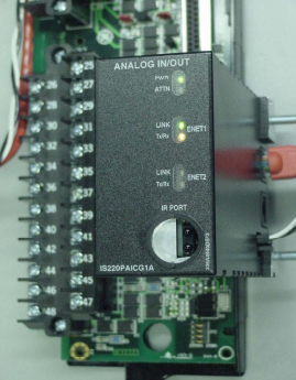
Terminal Blocks
Signal flow begins with a sensor connected to a terminal block on a board. There are
two types of boards available. T-type boards contain two 24 point, barrier-type,
removable, terminal blocks. Each point can accept two 3.0 mm2
(#12AWG) wires
with 300 V insulation per point with spade or ring type lugs. In addition, captive
clamps are provided for terminating bare wires. Screw spacing is 9.53 mm (0.375
inch) minimum, center-to-center.
A shield strip is provided next to each block, which is actually the left-hand side of
the metal base where the board is mounted. Wide and narrow boards are arranged in
vertical columns of high and low-level wiring that can be accessed from top and/or
bottom cable entrances. An example of a wide board is a board that contains
magnetic relays with fused circuits for solenoid drivers. T-type boards are normally
surface mounted, but can also be DIN-rail mounted.
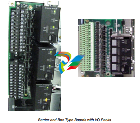
S-type boards have one I/O pack for simplex and dual redundant systems. They are
half the size of T-type boards and are DIN-rail or surface mounted. Two versions of
the boards are available, H1 and H3. H1 boards have fixed terminal blocks, and H3
boards have removable terminal blocks. A H2 version is available for mounting of
custom blocks such as spring-cage or insulation displacement.
S-type boards have box type terminal blocks that accept one 3.0 mm2
(#12AWG)
wire or two 2.0 mm2
(#14AWG) wires with 300 V insulation per point. Screw
spacing is 5.08 mm (0.2 inch) minimum, center-to-center. A shield strip is provided
to the left of each block. It can be connected to a metal base for immediate grounding
or floated to allow individual ground wires from each board to be wired to a
centralized, cabinet ground strip.
I/O Types
General purpose I/O is used for both turbine applications and process control.
Turbine-specific I/O is used for direct interface to the unique sensors and actuators
on turbines. This reduces or eliminates a substantial amount of interposing
instrumentation. As a result, many potential single point failures are eliminated in the
most critical area for improved running reliability and reduced long-term
maintenance. Direct interface to the sensors and actuators also enables the
diagnostics to directly interrogate the devices on the equipment for maximum
effectiveness. This data is used to analyze device and system performance. Also,
fewer spare parts are needed.
I/O Type - General Purpose Board
Redundant
Packs/Boards
24 DI (125 V dc, group isolated) 1 ms SOE TBCIH1 1 or 2 or 3
24 DI (24 V dc, group isolated) 1 ms SOE TBCIH2 1 or 2 or 3
24 DI (48 V dc, group isolated) 1 ms SOE TBCIH3 1 or 2 or 3
24 DI (115/230 V ac, 125 V dc, point isolated) 1 ms SOE on 125 V dc TBCIH1 1 or 2 or 3
24 DI (24 V dc, point isolated) TBCIH2 1 or 2 or 3
24 DI (24 V dc, group isolated) STCIH1 1
-
 GE IS200AEPBH1B IS200AEPBH1B‑REV‑AA Pitch-Charger Control PCB Board
 -
 GE IS200EDEXG1ADA EX2100 SCR Trigger Control Board
 -
 GE 151X1207CK01SA01 IS200EDEXG1A EX2100 SCR
 -
 GE 151X1233DD02SA02 IS200AEPBH1B - Variant for pitch control charger assembly
 -
 GE 151X1233DB01SA01 IS200AEPBH1B - 10kW Wind Power Converter
 -
 GE 151X1233DB01SA01R | IS200AEPBH1B 10KW Converter
 -
GE 151X1233DD01SA02 Pitch Battery Charger (109W6931P001)
-
GE 151X1233DD01SA02 Pitch Battery Charger Assy IS200AEPBH1B
-
 GE 151X1233DB02SA02 Rev A IS200AEPBH1B Wind Turbine Converter
 -
 GE 151X1207CK02SA02 SCR 4400 V 1850 A IS200EDEXG1ADA General Electric EX2100
 -
 Triconex 3723X 32-Channel TMR Analog Input Module with HART
 -
 SHINKAWA VM-21G SIGNAL CONDITIONER SOCKET
 -
SHINKAWA VM-21R REVOLUTION SIGNAL CONDITIONER
-
SHINKAWA VM-21T DISPLACEMENT INPUT THRUST SIGNAL CONDITIONER
-
SHINKAWA VM-21D 6-WIRE LVDT SIGNAL CONDITIONER
-
 SHINKAWA VM-21P 3-WIRE LVDT SIGNAL CONDITIONER
 -
SHINKAWA VM-21A VIBRATION SIGNAL CONDITIONER
-
SHINKAWA VM-21K DISPLACEMENT INPUT VIBRATION SIGNAL CONDITIONER
-
 SHINKAWA VM-25S01 CONDITION MONITORING SYSTEM
 -
SHINKAWA VM-25 CONDITION MONITORING SYSTEM
-
SHINKAWA VM-772B DEVICE CONFIG
-
SHINKAWA VM-771B MCL VIEW
-
 SHINKAWA VM-76B INSTRUMENT RACK
 -
SHINKAWA VM-75B POWER SUPPLY MODULE
-
 SHINKAWA VM-742B NETWORK COMMUNICATION MODULE
 -
 SHINKAWA VM-741B LOCAL COMMUNICATION & PHASE MARKER MODULE
 -
SHINKAWA VM-722B 9-CHANNEL RELAY MODULE
-
SHINKAWA VM-707B AERODERIVATIVE GAS TURBINE MONITOR MODULE
-
 SHINKAWA VM-706B ROD DROP MONITOR MODULE
 -
 SHINKAWA VM-705B 18-CHANNEL TEMPERATURE MONITOR MODULE
 -
 SHINKAWA VM-704B TEMPERATURE MONITOR MODULE
 -
 SHINKAWA VM-702B ABSOLUTE VIBRATION MONITOR MODULE
 -
SHINKAWA VM-701B VIBRATION / DISPLACEMENT MONITOR MODULE
-
 SHINKAWA MODEL VM-5X INTERFACE UNIT
 -
 SHINKAWA MODEL VM-5W2 DUAL POWER SUPPLY INSTRUMENT RACK
 -
 SHINKAWA MODEL VM-5H4 INSTRUMENT RACK (for VM-5Z5.6.7)
 -
SHINKAWA MODEL VM-5G SINGLE UNIT INSTRUMENT RACK
-
SHINKAWA MODEL VM-5Z5,6,7 POWER SUPPLY UNIT
-
SHINKAWA MODEL VM-5Y1,2,3 RELAY MODULE UNIT
-
 SHINKAWA MODEL VM-5P3 PHASE MARKER UNIT
 -
 SHINKAWA MODEL VM-53 DUAL COMMUNICATION UNIT
 -
 SHINKAWA MODEL VM-52 BOTTOM HOLD MONITOR
 -
SHINKAWA MODEL VM-51 ROD DROP MONITOR
-
SHINKAWA MODEL VM-5R TACHOMETER
-
SHINKAWA MODEL VM-5S DUAL TACHOMETER
-
SHINKAWA MODEL VM-5A DUAL VALVE
-
SHINKAWA MODEL VM-5E DUAL CASE
-
SHINKAWA MODEL VM-5L COMPLEMENTARY INPUT
-
SHINKAWA MODEL VM-5N RAMP DIFFERENTIAL
-
SHINKAWA MODEL VM-5D DUAL DIFFERENTIAL
-
SHINKAWA MODEL VM-5T DUAL THRUST MONITOR
-
SHINKAWA MODEL VM-5C ECCENTRICITY MONITOR
-
SHINKAWA MODEL VM-5M DUAL PATH MONITOR
-
SHINKAWA MODEL VM-5B DUAL ACCELERATION MONITOR
-
SHINKAWA MODEL VM-5U DUAL SEISMIC MONITOR
-
SHINKAWA MODEL VM-55 VIBRATION MONITOR
-
 SHINKAWA VM-742B1-5 VIBRATION MONITORING SYSTEM CARD
 -
 Shinkawa PSP-17B P-24-64A P-24-64B Circuit Board Module
 -
 SHINKAWA MGP-67 PCB
 -
 Shinkawa JBP-278 P-22-48A-1 P-22-48B-1 Circuit Board Module
 -
 Shinkawa VM-721B 18-CHANNEL RELAY MODULE
 -
Shinkawa FRP-337 P-26-54A P-26-54B Circuit Board Module
-
 Shinkawa CPP-111 P-25-59A P-25-59B Circuit Board Module
 -
Shinkawa WKN-142K2-2 Vibration Transmitter
-
 SHINKAWA VL-202A08L-1012 Rotor Position Monitor Probe Sensor
 -
 Shinkawa CPP-128 P-26-74A P-26-74B Circuit Board Module
 -
 Honeywell 51402755-100 PROCESSOR CARD
 -
 Honeywell 51107595-100 Power
 -
HONEYWELL 51304544-100 Control Board
-
 HONEYWELL 51109919-100 BOARD
 -
 HHoneywell 51204160-175 Digital Input Module
 -
 Honeywell 51304754-150 High Level Analog Input Module
 -
 HONEYWELL 51304690-100 DIGITAL INPUT CARD
 -
 Honeywell 51401635-150 COMM CONTROL
 -
 HONEYWELL 51204174-175 MC-TAOY 52 ANALOG OUTPUT BOARD
 -
 HONEYWELL 51400596-100
 -
 HONEYWELL 51401291-100 board card
 -
 HONEYWELL 51401642-150 I/O LINK MODULE
 -
 Honeywell LCN‑E Hub Power Supply 38500148‑300
 -
 Honeywell LCN‑E Hub redundant 38500143‑202 Twisted‑pair LCN
 -
 Honeywell LCN‑E Hub non‑redundant,38500143‑102
 -
Honeywell Enhanced Micro‑TDC‑3000 System Unit MX‑DTAC01K2
-
 Honeywell Enhanced Micro‑TDC‑3000 System Unit MX‑DTAB01K2
 -
 Honeywell Enhanced Micro‑TDC‑3000 System Unit MT11‑520
 -
 Honeywell STI‑CE Smart Transmitter Interface 51304516‑150
 -
 Honeywell STI Smart Transmitter Interface 51304516‑100 MC‑PSTX02
 -
 Honeywell ulse Counter IOP,51304386‑100.MU‑PPIX02
 -
 Honeywell DO Digital Output IOP‑CE 51304487‑150 CE version
 -
.png) Honeywell DO Digital Output IOP 51304487‑100 MC‑PDOX02
Honeywell DO Digital Output IOP 51304487‑100 MC‑PDOX02 -
 Honeywell TDC‑3000 SOE DI IOP,51402625-175 MC‑PDIS12
 -
 Honeywell TDC‑3000 DI Digital Input IOP‑CE 51304485‑150
 -
Honeywell TDC‑3000 DI Digital Input IOP 51304485‑100 MC‑PDIX02
-
Honeywell TDC‑3000 AO Analog Output IOP 51304757‑100 MU‑PAOX02
-
Honeywell TDC‑3000 TC Thermocouple IOP 51304756‑100 MU‑TAMT03
-
 Honeywell TDC‑3000 51304755‑100 MU‑TAMR03
 -
 Honeywell TDC‑3000 LLAI Multiplex AI IOP,51304362‑150
 -
 Honeywell TDC‑3000 HLAI Analog Input IOP‑CE,51304363‑150
 -
 Honeywell TDC‑3000 HLAI Analog Input IOP,51304363‑100.4‑20mA
 -
Honeywell TDC‑3000 HPM Power Supply,51401731‑100
-
 Honeywell TDC‑3000 Standard 1986.HPM High‑Performance PM CPU,51402362‑100
 -
Honeywell TDC‑3000 APM Advanced Process Manager CPU,51304459‑100
-
Honeywell TDC‑3000 Standard 1986.PM Process Manager CPU,51304362‑100
-
Honeywell TDC‑3000 NIM Network Interface Module,51304481‑200
-
 Honeywell TDC‑3000 NIM Network Interface Module 51304481‑100
 -
 Honeywell TDC‑3000 BASIC,LCN Terminator Resistor,30732052‑001.Coaxial
 -
Honeywell TDC‑3000 BASIC,Hiway Coupler,30753732-001
-
 Honeywell TDC‑3000 BASIC,LEPIU Low‑Energy PIU,4DP7APCFA309
 -
Honeywell TDC‑3000 BASIC,HLPIU High‑Level PIU,4DP7APCFA106
-
Honeywell TDC‑3000 BASIC,Multifunction Controller(TDC‑2000 DHW),4DP7MFA103
-
 Honeywell TDC‑3000 BASIC,Extended Controller(TDC‑2000 DHW),4DP7AXA102
 -
Honeywell TDC‑3000 BASIC,Basic Controller(TDC‑2000 DHW),4DP7BBA101
-
Honeywell TDC‑3000 BASIC,XLCNE2 LCN Extender,51305508‑100.Coaxial LCN
-
 Honeywell TDC‑3000 BASIC,E‑PLCG PLC Gateway,51400997‑200
 -
 Honeywell TDC‑3000 BASIC,PLNM Plant Network Module,51401163‑100
 -
 Honeywell TDC‑3000 BASIC,CG Computer Gateway,80360206‑001
 -
 Honeywell TDC‑3000 BASIC,HG High‑Speed Gateway,51304526‑100
 -
 Honeywell TDC‑3000 BASIC,HM History Module,51191596‑200
 -
Honeywell TDC‑3000 BASIC,HM History Module,51191596‑100
-
Honeywell TDC‑3000 BASIC,AM Application Module CPU,51401551‑800.K2LCN‑8
-
Honeywell TDC‑3000 BASIC,AM Application Module CPU,51401551‑600.K2LCN‑6
-
 Honeywell TDC‑3000 BASIC,AM Application Module CPU,51401551‑400,K2LCN‑4
 -
 Honeywell TDC‑3000 BASIC,AM Application Module CPU,51401551‑300.K2LCN‑3
 -
Honeywell TDC‑3000 BASIC,AM Application Module CPU,51401551‑200,K2LCN‑2
-
 Honeywell TDC‑3000 BASIC,US Universal Station CPU,51401288‑200
 -
TDC‑3000 BASIC,US Universal Station CPU,51401288‑100
-
 SHINKAWA VM-21P1 Signal Conditioner 0-50MM 24VDC
 -
 Shinkawa RiverNew Vibration Transducer VK202 Series
 -
 Shinkawa Electric VM-3E2 Vibration Monitor Module


