
GE Energy Mark* VIe Control Product Description
and are mounted on a DIN-rail. LEDs indicate the status of the IONet link, speed,
activity, and duplex.
100BaseTx 100BaseFx
IEEE specification 802.3u 802.3u
Wire speed 100 Mbps 100 Mbps
Cable type UTP Cat. 5 Fiber (multi-mode)
Connector type RJ-45 SC
Maximum length of a segment at full-duplex 100 m/328 ft 2 km/6,600 ft
Maximum taps per segment 2 2
Maximum I/O packs per network 199 199
Maximum number of switches 2 2
Topology Star Star
Operator and Maintenance Tools
Operator Interface
The operator interface is commonly referred to as the Human-Machine Interface
(HMI). It is a computer with a Microsoft® Windows-based operating system,
client/server capability, a CIMPLICITY® graphics display system, and software
maintenance tools (ToolboxST). It can be applied as:
• Primary operator station for one unit or the entire plant
• Maintenance station gateway
• Engineers station
• Gateway for communications
All local and remote data in
the Mark VIe is accessible for
screens with high-resolution
time tags for alarms and
events.
The HMI can be re-initialized or replaced with the process running with no impact
on the control system. It communicates with the main processor board in the Mark
VIe controller(s) through the control network Unit Data Highway (UDH) and to
third-party control and monitoring systems through the information network Plant
Data Highway (PDH).
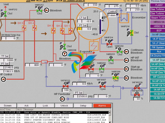
System (process) alarms for fault conditions are time-tagged at frame rate in the
controller(s) and transmitted to the HMI alarm management system. System events
are time-tagged at frame rate, and sequence of events (SOE) for contact inputs are
time-tagged at 1 ms in the I/O packs. Alarms can be sorted according to ID,
Resource, Device, Time, and Priority. Operators can add comments to alarm
messages or link specific alarm messages to supporting graphics.
A standard alarm/event log stores data for 30 days and can be sorted in chronological
order or according to the frequency of occurrence. In addition, a trip history is
provided that stores the key control parameters and alarms/events for the last 30
trips. This includes up to 200 alarms, 200 events, 200 SOE messages, and analog
data before and after the trip.
Data is displayed in English or Metric engineering units with a one-second update
rate and one second to repaint a typical display graphic. Operator commands can be
issued to increment/decrement a setpoint, or a numerical value can be entered for a
new setpoint.
Security for HMI users is important to restrict access to certain maintenance
functions, such as editors and tuning capability, and to limit certain operations.
A system called User Accounts is provided to limit access or use of particular HMI
features.
Software Maintenance Tools (ToolboxST)
The Mark VIe is a fully programmable control system. Application software is
maintained by factory software automation tools that select proven GE control and
protection algorithms and integrate them with the I/O, sequencing, and displays for
each application. Multiple block libraries are provided with general-purpose blocks,
math blocks, macros (user blocks), and application-specific blocks.
Changes to the application software can be made with multi-level password
protection and downloaded to the controller(s) while the system is running without
rebooting the main processors. In redundant control systems, the application
software in each controller is identical, and is represented as a single program to
maintenance personnel. Downloads of changes are automatically distributed to the
redundant controllers by the control system, and any discrepancies between the
controllers are monitored by diagnostics. All application software is stored in the
controller(s) in non-volatile memory.
Application software is run sequentially, and dynamic data displays in function block
and ladder diagram formats. Maintenance personnel can add, delete, or change
analog loops, sequencing, I/O assignments, and tuning constants. To simplify
editing, data points can be selected, dragged, and dropped on the screen from one
block to another. Points can also be dragged from the application software diagrams
onto trends. Other features include Boolean (digital) forcing, analog forcing, and
trending at the rate the application software is running, frame rate.
Application software documentation is created directly from source code and can be
compiled and printed at the site. This includes the application software diagram, I/O
assignments, the settings of tuning constants, and such. The software maintenance
tools are available for use in the HMI or as a separate software package on a
Windows-based computer.
Diagnostics
High/low (hardware) limit checking is provided for each analog input. These limits
-
 GE IS200AEPBH1B IS200AEPBH1B‑REV‑AA Pitch-Charger Control PCB Board
 -
 GE IS200EDEXG1ADA EX2100 SCR Trigger Control Board
 -
 GE 151X1207CK01SA01 IS200EDEXG1A EX2100 SCR
 -
 GE 151X1233DD02SA02 IS200AEPBH1B - Variant for pitch control charger assembly
 -
 GE 151X1233DB01SA01 IS200AEPBH1B - 10kW Wind Power Converter
 -
 GE 151X1233DB01SA01R | IS200AEPBH1B 10KW Converter
 -
GE 151X1233DD01SA02 Pitch Battery Charger (109W6931P001)
-
GE 151X1233DD01SA02 Pitch Battery Charger Assy IS200AEPBH1B
-
 GE 151X1233DB02SA02 Rev A IS200AEPBH1B Wind Turbine Converter
 -
 GE 151X1207CK02SA02 SCR 4400 V 1850 A IS200EDEXG1ADA General Electric EX2100
 -
 Triconex 3723X 32-Channel TMR Analog Input Module with HART
 -
 SHINKAWA VM-21G SIGNAL CONDITIONER SOCKET
 -
SHINKAWA VM-21R REVOLUTION SIGNAL CONDITIONER
-
SHINKAWA VM-21T DISPLACEMENT INPUT THRUST SIGNAL CONDITIONER
-
SHINKAWA VM-21D 6-WIRE LVDT SIGNAL CONDITIONER
-
 SHINKAWA VM-21P 3-WIRE LVDT SIGNAL CONDITIONER
 -
SHINKAWA VM-21A VIBRATION SIGNAL CONDITIONER
-
SHINKAWA VM-21K DISPLACEMENT INPUT VIBRATION SIGNAL CONDITIONER
-
 SHINKAWA VM-25S01 CONDITION MONITORING SYSTEM
 -
SHINKAWA VM-25 CONDITION MONITORING SYSTEM
-
SHINKAWA VM-772B DEVICE CONFIG
-
SHINKAWA VM-771B MCL VIEW
-
 SHINKAWA VM-76B INSTRUMENT RACK
 -
SHINKAWA VM-75B POWER SUPPLY MODULE
-
 SHINKAWA VM-742B NETWORK COMMUNICATION MODULE
 -
 SHINKAWA VM-741B LOCAL COMMUNICATION & PHASE MARKER MODULE
 -
SHINKAWA VM-722B 9-CHANNEL RELAY MODULE
-
SHINKAWA VM-707B AERODERIVATIVE GAS TURBINE MONITOR MODULE
-
 SHINKAWA VM-706B ROD DROP MONITOR MODULE
 -
 SHINKAWA VM-705B 18-CHANNEL TEMPERATURE MONITOR MODULE
 -
 SHINKAWA VM-704B TEMPERATURE MONITOR MODULE
 -
 SHINKAWA VM-702B ABSOLUTE VIBRATION MONITOR MODULE
 -
SHINKAWA VM-701B VIBRATION / DISPLACEMENT MONITOR MODULE
-
 SHINKAWA MODEL VM-5X INTERFACE UNIT
 -
 SHINKAWA MODEL VM-5W2 DUAL POWER SUPPLY INSTRUMENT RACK
 -
 SHINKAWA MODEL VM-5H4 INSTRUMENT RACK (for VM-5Z5.6.7)
 -
SHINKAWA MODEL VM-5G SINGLE UNIT INSTRUMENT RACK
-
SHINKAWA MODEL VM-5Z5,6,7 POWER SUPPLY UNIT
-
SHINKAWA MODEL VM-5Y1,2,3 RELAY MODULE UNIT
-
 SHINKAWA MODEL VM-5P3 PHASE MARKER UNIT
 -
 SHINKAWA MODEL VM-53 DUAL COMMUNICATION UNIT
 -
 SHINKAWA MODEL VM-52 BOTTOM HOLD MONITOR
 -
SHINKAWA MODEL VM-51 ROD DROP MONITOR
-
SHINKAWA MODEL VM-5R TACHOMETER
-
SHINKAWA MODEL VM-5S DUAL TACHOMETER
-
SHINKAWA MODEL VM-5A DUAL VALVE
-
SHINKAWA MODEL VM-5E DUAL CASE
-
SHINKAWA MODEL VM-5L COMPLEMENTARY INPUT
-
SHINKAWA MODEL VM-5N RAMP DIFFERENTIAL
-
SHINKAWA MODEL VM-5D DUAL DIFFERENTIAL
-
SHINKAWA MODEL VM-5T DUAL THRUST MONITOR
-
SHINKAWA MODEL VM-5C ECCENTRICITY MONITOR
-
SHINKAWA MODEL VM-5M DUAL PATH MONITOR
-
SHINKAWA MODEL VM-5B DUAL ACCELERATION MONITOR
-
SHINKAWA MODEL VM-5U DUAL SEISMIC MONITOR
-
SHINKAWA MODEL VM-55 VIBRATION MONITOR
-
 SHINKAWA VM-742B1-5 VIBRATION MONITORING SYSTEM CARD
 -
 Shinkawa PSP-17B P-24-64A P-24-64B Circuit Board Module
 -
 SHINKAWA MGP-67 PCB
 -
 Shinkawa JBP-278 P-22-48A-1 P-22-48B-1 Circuit Board Module
 -
 Shinkawa VM-721B 18-CHANNEL RELAY MODULE
 -
Shinkawa FRP-337 P-26-54A P-26-54B Circuit Board Module
-
 Shinkawa CPP-111 P-25-59A P-25-59B Circuit Board Module
 -
Shinkawa WKN-142K2-2 Vibration Transmitter
-
 SHINKAWA VL-202A08L-1012 Rotor Position Monitor Probe Sensor
 -
 Shinkawa CPP-128 P-26-74A P-26-74B Circuit Board Module
 -
 Honeywell 51402755-100 PROCESSOR CARD
 -
 Honeywell 51107595-100 Power
 -
HONEYWELL 51304544-100 Control Board
-
 HONEYWELL 51109919-100 BOARD
 -
 HHoneywell 51204160-175 Digital Input Module
 -
 Honeywell 51304754-150 High Level Analog Input Module
 -
 HONEYWELL 51304690-100 DIGITAL INPUT CARD
 -
 Honeywell 51401635-150 COMM CONTROL
 -
 HONEYWELL 51204174-175 MC-TAOY 52 ANALOG OUTPUT BOARD
 -
 HONEYWELL 51400596-100
 -
 HONEYWELL 51401291-100 board card
 -
 HONEYWELL 51401642-150 I/O LINK MODULE
 -
 Honeywell LCN‑E Hub Power Supply 38500148‑300
 -
 Honeywell LCN‑E Hub redundant 38500143‑202 Twisted‑pair LCN
 -
 Honeywell LCN‑E Hub non‑redundant,38500143‑102
 -
Honeywell Enhanced Micro‑TDC‑3000 System Unit MX‑DTAC01K2
-
 Honeywell Enhanced Micro‑TDC‑3000 System Unit MX‑DTAB01K2
 -
 Honeywell Enhanced Micro‑TDC‑3000 System Unit MT11‑520
 -
 Honeywell STI‑CE Smart Transmitter Interface 51304516‑150
 -
 Honeywell STI Smart Transmitter Interface 51304516‑100 MC‑PSTX02
 -
 Honeywell ulse Counter IOP,51304386‑100.MU‑PPIX02
 -
 Honeywell DO Digital Output IOP‑CE 51304487‑150 CE version
 -
.png) Honeywell DO Digital Output IOP 51304487‑100 MC‑PDOX02
Honeywell DO Digital Output IOP 51304487‑100 MC‑PDOX02 -
 Honeywell TDC‑3000 SOE DI IOP,51402625-175 MC‑PDIS12
 -
 Honeywell TDC‑3000 DI Digital Input IOP‑CE 51304485‑150
 -
Honeywell TDC‑3000 DI Digital Input IOP 51304485‑100 MC‑PDIX02
-
Honeywell TDC‑3000 AO Analog Output IOP 51304757‑100 MU‑PAOX02
-
Honeywell TDC‑3000 TC Thermocouple IOP 51304756‑100 MU‑TAMT03
-
 Honeywell TDC‑3000 51304755‑100 MU‑TAMR03
 -
 Honeywell TDC‑3000 LLAI Multiplex AI IOP,51304362‑150
 -
 Honeywell TDC‑3000 HLAI Analog Input IOP‑CE,51304363‑150
 -
 Honeywell TDC‑3000 HLAI Analog Input IOP,51304363‑100.4‑20mA
 -
Honeywell TDC‑3000 HPM Power Supply,51401731‑100
-
 Honeywell TDC‑3000 Standard 1986.HPM High‑Performance PM CPU,51402362‑100
 -
Honeywell TDC‑3000 APM Advanced Process Manager CPU,51304459‑100
-
Honeywell TDC‑3000 Standard 1986.PM Process Manager CPU,51304362‑100
-
Honeywell TDC‑3000 NIM Network Interface Module,51304481‑200
-
 Honeywell TDC‑3000 NIM Network Interface Module 51304481‑100
 -
 Honeywell TDC‑3000 BASIC,LCN Terminator Resistor,30732052‑001.Coaxial
 -
Honeywell TDC‑3000 BASIC,Hiway Coupler,30753732-001
-
 Honeywell TDC‑3000 BASIC,LEPIU Low‑Energy PIU,4DP7APCFA309
 -
Honeywell TDC‑3000 BASIC,HLPIU High‑Level PIU,4DP7APCFA106
-
Honeywell TDC‑3000 BASIC,Multifunction Controller(TDC‑2000 DHW),4DP7MFA103
-
 Honeywell TDC‑3000 BASIC,Extended Controller(TDC‑2000 DHW),4DP7AXA102
 -
Honeywell TDC‑3000 BASIC,Basic Controller(TDC‑2000 DHW),4DP7BBA101
-
Honeywell TDC‑3000 BASIC,XLCNE2 LCN Extender,51305508‑100.Coaxial LCN
-
 Honeywell TDC‑3000 BASIC,E‑PLCG PLC Gateway,51400997‑200
 -
 Honeywell TDC‑3000 BASIC,PLNM Plant Network Module,51401163‑100
 -
 Honeywell TDC‑3000 BASIC,CG Computer Gateway,80360206‑001
 -
 Honeywell TDC‑3000 BASIC,HG High‑Speed Gateway,51304526‑100
 -
 Honeywell TDC‑3000 BASIC,HM History Module,51191596‑200
 -
Honeywell TDC‑3000 BASIC,HM History Module,51191596‑100
-
Honeywell TDC‑3000 BASIC,AM Application Module CPU,51401551‑800.K2LCN‑8
-
Honeywell TDC‑3000 BASIC,AM Application Module CPU,51401551‑600.K2LCN‑6
-
 Honeywell TDC‑3000 BASIC,AM Application Module CPU,51401551‑400,K2LCN‑4
 -
 Honeywell TDC‑3000 BASIC,AM Application Module CPU,51401551‑300.K2LCN‑3
 -
Honeywell TDC‑3000 BASIC,AM Application Module CPU,51401551‑200,K2LCN‑2
-
 Honeywell TDC‑3000 BASIC,US Universal Station CPU,51401288‑200
 -
TDC‑3000 BASIC,US Universal Station CPU,51401288‑100
-
 SHINKAWA VM-21P1 Signal Conditioner 0-50MM 24VDC
 -
 Shinkawa RiverNew Vibration Transducer VK202 Series
 -
 Shinkawa Electric VM-3E2 Vibration Monitor Module


