
SYNCHROTACT® 5 Operating Instructions SYN 5201 SYN 5202
Functional principle
2.1 Brief description
The SYNCHROTACT 5 digital synchronizer is used for automatic synchronizing and
paralleling of generators with lines and for the paralleling of already synchronous lines.
The device is designed for system frequencies of either 50/60 Hz or 16 2
/3 Hz.
SYN 5201 is a single-channel synchronizing device whose component choice and
software design provides the highest security against incorrect paralleling.
SYN 5202 consists of two independent channels with different hardware and software.
This dual-channel property maximizes security against incorrect paralleling.
All parameters required for paralleling are stored in a parameter set. The paralleling
conditions and the characteristics of the voltage and frequency matchers are defined in
this set. With the option providing seven parameter sets, paralleling can be carried out
under different conditions or with different matcher characteristics using the same
device. Seven configurable digital inputs and outputs are available for the selection and
back indication of a parameter set.
The data which are important for commissioning and for control purposes can be
uploaded or downloaded using the PC tool SynView or, alternatively, via the keypad on
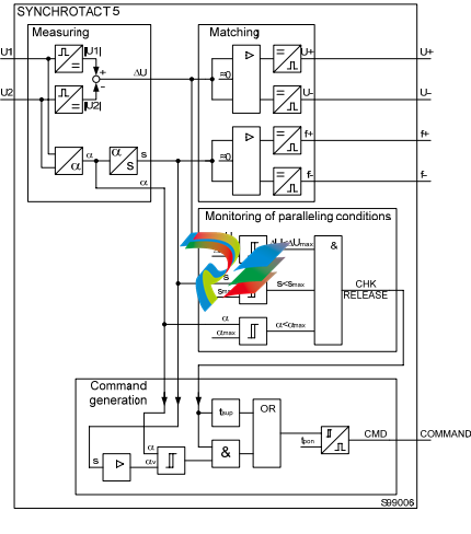
Paralleling functions
The automatic paralleling process can basically be divided into four function blocks:
1. Measuring
2. Voltage and frequency matching
3. Monitoring of paralleling conditions
4. Paralleling command generation
In the following figure, the block circuit diagram of the basic paralleling functions of
SYNCHROTACT 5 is simplified and shows a single-channel configuration. The
individual functions are described more precisely in the following sections.
Measuring
The following measured variables are generated from the two single-phase measuring
voltages:
Voltage U1, U2
U1 is the reference voltage e.g. line
U2 is the adjustable voltage e.g. generator.
Frequency f1, f2
f1 is the reference frequency
f2 is the adjustable frequency.
Voltage difference ΔU
ΔU = IU1I – IU2I
ΔU > 0 Adjustable voltage is lower
ΔU < 0 Adjustable voltage is higher
Slip s
%100*
1
21
f
ff s − =
s > 0 Adjustable frequency is less (e.g. generator is sub-synchronous)
s < 0 Adjustable frequency is greater (e.g. generator is oversynchronous)
Phase-angle difference α
α ϕ −= ϕ21
α > 0 Adjustable frequency is lagging
α < 0 Adjustable frequency is leading
Acceleration ds/dt
dtds [ ]ss
x
x
x /%*2/
56
1
∑
=
=
Δ=
(Every 0.5 s, an average value is formed from 56 measurements; sampling period:
9 ms)
ds/dt > 0 Adjustable frequency is reduced (e.g. generator accelerates)
ds/dt < 0 Adjustable frequency increases (e.g. generator is slowed down)
With SYN 5202, the measurement is carried out separately for each channel. It is
possible to carry out three-phase measurements in order to detect connection faults
(rotary field, polarity) and losses of phase.
Voltage measurement (SYN 5202: channel 1)
The two input voltages U1 and U2 are passed to the processor via high-impedance input
resistors, differential amplifiers, low-pass filters and A/D converters.
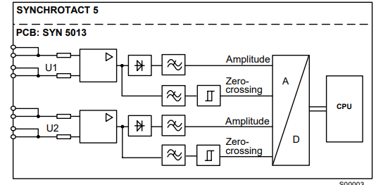
Voltage measurement channel 2 (SYN 5202 only)
The two input voltages U1 and U2 are passed through high-impedance input resistors
and differential amplifiers. The signal for the amplitude value is formed from this by
conversion and filtering . For zero-passage detection, the signal is filtered and passed
through a comparator. The signals prepared in this way are passed to the processor via
the A/D converter
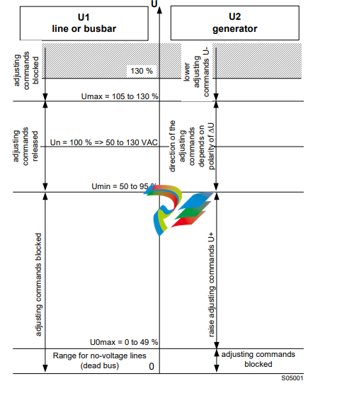
Voltage and frequency matching
Working range of the voltage matcher
If the voltage U1 is in the range between Umin and Umax and the voltage U2 is greater
than U0max the adjusting commands are released. The direction of the adjusting
commands depends on the polarity of ΔU.
As an additional condition, both frequencies must be in the range fn±5 Hz.
Voltage matcher with variable pulse times
The voltage matcher issues a command the length of which is proportional to the current
voltage difference. The proportionality factor dU/dt can be adapted to the voltage
regulator. The voltage matcher aims at a value in the middle of the set tolerance band.
The adjusting command length tp U is:
dtdU
U U
U
tpU /
2
max max
⎟
⎟
⎠
⎞
⎜
⎜
⎝
⎛ Δ−−Δ+
−Δ
=
The adjusting pulse is discontinued as soon as the voltage difference passes through
the target value. The command length does not fall below a settable minimum value.
After an adjusting command, the system waits for the set pulse interval ts U so that the
actual values can stabilise to the new setpoint.
Voltage matching with variable intervals
The function INVERSE U changes the way the voltage matcher functions. The pulses
are now always the same length, but the intervals are inversely proportional to the
voltage difference.
Pulse length: adjustable by means of the parameter tp Umin: tp = tp Umin
Pause interval: adjustable by means of the parameter ts U; dependent on ts U and
±ΔUmax:
[( ) ( )] 0
2
max max
*325,01* ≥
⎪⎭
⎪
⎬
⎫
⎪⎩
⎪
⎨
⎧
⎥
⎥
⎦
⎤
⎢
⎢
⎣
⎡ Δ−+Δ+ = −Δ−
U U
Utsts U
Voltage matcher for tap changer
The function TAP CHANGER allows constant pulse durations and pulse intervals to be
generated, which is necessary for matching by means of the tap changer.
Frequency matcher with variable pulse durations
The frequency matcher issues a command the length of which is proportional to the
current slip. The proportionality factor df/dt can be adapted to the governor. The
frequency matcher aims at a value midway between the nearer slip limit and zero. The
adjusting command length tpf is:
dtdf
s
s
tpf /
2
± max
−±
=
Between 1/3 and 2/3 of smax there is a range where no adjustment takes place. The
adjusting pulse is discontinued as soon as the slip passes through zero. The command
length does not fall below a settable minimum value. After an adjusting command, the
system waits for the set pulse interval ts f so that the actual values can stabilise to the
new setpoint.
Frequency matcher with variable intervals
The function INVERSE f changes the way the frequency matcher functions. The pulses
are now always the same length, but the intervals are inversely proportional to the slip.
Pulse length: adjustable by means of the parameter tp fmin: tp = tp fmin
Pause interval: is calculated according to the following formula (can not be set as a
parameter):
[ ]s
sfff
ts 30
*1
1
21
1
≤= − =
2.2.3 Monitoring of paralleling conditions
The monitoring of the paralleling conditions can be divided into these parallel-functioning
blocks:
• voltage-carrying lines
• no-voltage lines
Paralleling of two voltage-carrying lines
The monitoring of the paralleling conditions enables a paralleling command (CHK
RELEASE) if the following conditions are fulfilled simultaneously:
• the phase-angle difference is within the tolerance band
• the slip is within the tolerance band
• the voltage difference is within the tolerance band
• the voltage does not fall below minimum voltage
• the maximum voltage is not exceeded
• the device is in operating status (OPERATING)
• nominal frequency deviation ≤ 5 Hz
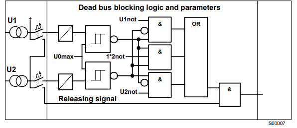
Paralleling of no-voltage lines (dead bus)
A special case for the monitoring is the paralleling of no-voltage lines. A paralleling
command release is only issued if the external release signal is active and the
measuring logic enables the release at the same time. The release by the measuring
logic can be enabled if both voltages are within one of the permitted ranges. The dead
bus range can be defined as permissible for one, the other or both measuring voltages
by means of the parameters U1not, U2not and 1*2not.
The monitoring of the paralleling conditions (CHK RELEASE) releases the paralleling
command if the following conditions are fulfilled simultaneously:
• the releasing signal for dead bus (digital input) is issued
• the zero voltage(s) does not exceed the set threshold U0max
• the current voltage does not fall below the minimum voltage
• the current voltage does not exceed the maximum voltage
• the current zero voltage situation corresponds to a configuration permitted by means
of U1not, U2not, 1*2not
• the device is in Operating status (OPERATING)
2.2.4 Command generation
The command generation makes a distinction between asynchronous and synchronous
sources or no-voltage lines. Two modes, one for asynchronous and one for synchronous
sources, run in parallel, so that a source can be asynchronous or synchronous at any
time. The paralleling command is issued in the mode in which all conditions are fulfilled
first.
In SYN 5202 the actuation of the paralleling relays takes place separately in both
channels.
Asynchronous sources
It is called asynchronous sources, if the two lines to be paralleled (or generator and line)
are asynchronous before the circuit breaker is closed.
From the slip s, the acceleration ds/dt, the line frequency f1 and the set paralleling time
t on, the command generation calculates the necessary lead angle αv by which the
paralleling command is shifted forward in time so that the main contacts close exactly on
phase coincidence (see following figure):
⎥
⎦
⎤ ⎢
⎣
⎡ = + ont
ontdtds sfv *
2
*/
α *1*6,3
If the measured phase-angle difference α corresponds to the lead angle αv and if all
paralleling conditions are fulfilled at the same time (CHK RELEASE), a command is
generated (COMMAND).
The command length always corresponds to the set paralleling command length tp on. If
the latter is set to OFF or zero, the command generation is no longer in operation. The
device then functions like a synchrocheck; as soon as the release is given by the
monitoring (CHK RELEASE) the contacts close, when the release is dropped they open
again.


-
 Hirschmann RS20-1600M2T1SDAEHH03.1.02 Rail Switch
 -
 Hirschmann BRS30-24TX Industrial Rail Switch
 -
 Hirschmann RSPM20-4T14T1EV9HHS999.9.99 Managed Ethernet Switch
 -
 Hirschmann BELDEN RS40-0009CCCCSDAPHH09.0.14 / RS400009CCCCSDAPHH09014
 -
Hirschmann RS40 Rail Switch RS40-0009CCCCSDAE
-
 Hirschmann BELDEN RS30-0802T1T1SDAP / RS300802T1T1SDAP Fully Managed Layer 2 Compact Rail Switch
 -
 Hirschmann BELDEN RS20-0800M2M2SDAUHH / RS200800M2M2SDAUHH
 -
 Hirschmann EAGLE30-04022O6TT999SCCY9HSE3F Industrial Firewall Router Switch
 -
 Hirschmann RS20-1600T1T1SDAEHH09.0.14 RS20 Rail Mount Ethernet Switch
 -
 Hirschmann EAGLE0200T1T1TDDY90000HHE05.3.03 Industrial Security Router
 -
Hirschmann - BELDEN MIPP-AD-1L9P
-
 HIRSCHMANN RSPM20-4Z64Z6TV9HHS9 942 106-999 RAIL SAFETY SWITCH
 -
 HIRSCHMANN FIBEROPTIC MODULE FIP P/N: OZDFIPG3T
 -
 HIRSCHMANN RS20-1600M2M2SDAUHH Ethernet rack-mounted switch
 -
 HIRSCHMANN BELDEN RS20-0400T1T1SDAEHH04.0.01 / RS200400T1T1SDAEHH04001
 -
HIRSCHMANN MM2-4FXM3 MICE Media Module
-
HIRSCHMANN RS20-0800M2M2SDAE Industrial Ethernet Rail Switch
-
 Hirschmann RS20-2400T1T1SDAP / RS20-2400T1T1SDAPHH05.0.02
 -
 GE MLJ1005B010H00C MLJ Digital Synchromism Check
 -
 ALSTOM MICROTECH DX21-M2 Digital Excitation Controller
 -
HIRSCHMANN BRS20-1200ZZZZ-STCY99HHSES
-
 HIRSCHMANN MM3-4FXM2 MICE Media Module
 -
Hirschmann RSB20-0800T1T1SAABHH 8Port ENet Rail Switch RSB20
-
 Hirschmann MACH102-8TP Ethernet Switch
 -
 SAACKE DDZ-M marine steam pressure atomizer
 -
 SAACKE SKV-A marine rotary cup atomizer
 -
 SAACKE Seavis HMI05e
 -
 Kollmorgen MMC-SD-2.0-230 Servo Drive 100-240VAC 2KW 10A Output 3PH 100-240VAC
 -
 Kollmorgen Servo drive CR10550
 -
 Kollmorgen AKD-P01207-NACN-0054 Servo Driver
 -
 Kollmorgen S406M-CA-036 Servostar
 -
.png) Kollmorgen AKD-B02407-NAAN-0000 Digital Servo Drive
Kollmorgen AKD-B02407-NAAN-0000 Digital Servo Drive -
 Kollmorgen SERVOSTAR S406AM-CA Digital Servo Drive
 -
 KOLLMORGEN SERVOSTAR 603-AS SERVO AMPLIFIER_SERVOSTAR603AS_S60301
 -
Kollmorgen S700 Servo Controller (S70602-NANANA-NA)
-
 Kollmorgen MPK411 controller
 -
 KOLLMORGEN MMC-SD-1.3-460-D Smart Drive
 -
 KOLLMORGEN AKM21C-CKB2AA-00 / AKM21CCKB2AA00 Servomotor
 -
 BECKHOFF AX5106-0000-0200 | Digital Compact Servo Drives 1-channel
 -
 BECKHOFF C3620-0000 INDUSTRIAL COMPUTER (MOTORSHELVES)
 -
 Beckhoff EK1960-0000 TwinSAFE Compact Controller
 -
 Beckhoff C6930-0050 Control Cabinet Industrial PC
 -
 Beckhoff CP7711-0001-0030 Industrial Computer Detection
 -
 Beckhoff CX1001-0111 Embedded PC CPU Module
 -
 Beckhoff C6017-0020 | Ultra-compact Industrial PC
 -
 Beckhoff EK1322 | 2-port EtherCAT P junction with feed-in
 -
 Beckhoff CP2219-0010 Panel
 -
 BECKHOFF C6015-0020 ULTRA COMPACT INDUSTRIAL PC
 -
 BECKHOFF CX2030-0120/Standard CPU Module Embedded PC Windows PLC controller
 -
 Beckhoff CP7721-1090-0020 Panel PC
 -
 Beckhoff PC CPU Module CX5130-0175
 -
 Beckhoff C6920-0050 Control Cabinet
 -
 Beckhoff EL6631 EtherCAT 2-Port Communication Interface, Profinet RT Controller
 -
 Beckhoff CP6202-0001-0060 touch screen panel PC
 -
 Beckhoff CP3916-1002-0000 Multi-Touch Control Panel
 -
 Beckhoff EP1809-0021 | EtherCAT Box, 16-channel digital input, 24 V DC, 3 ms, M8Preferred type
 -
 Beckhoff CX8190 PLC Embedded Industrial PC Ethernet Controller
 -
 Beckhoff CX2100-0914 Power Supply for External
 -
 Beckhoff Automation CP6906-0001-0000 HMI
 -
 Beckhoff EP7342-0002 Module
 -
 Beckhoff CX1020-0112 / CX1100-0910 / CX1020-N010 / CX1100-0003 Windows CPU
 -
 Beckhoff EP7211-0034 EtherCAT Box 1 Channel Motion Interface
 -
 Beckhoff C6240-0030 Control cabinet Industrial PC
 -
 beckhoff motherboard CB1052-0004 CB1052-0004
 -
 Beckhoff AX2006-AS Servo Drive / Variable Frequency Drive
 -
BECKHOFF CP6207-0001-0020 NSMP
-
 Beckhoff C6930-1142-0060 Industrial Computer
 -
 Beckhoff FC7501-0000 interface card
 -
 Beckhoff CX5140-0175 Embedded PC PLC CPU CX5140 Industrial Controller
 -
 Beckhoff CP7802-1100-0010: High-End IP65 Control Panel with DVI/USB Extended Interface
 -
BECKHOFF CP3716-1058-0010 CONTROL PANEL
-
 Beckhoff AX8108-0000 Single-Axis Module
 -
 Beckhoff CU8851-0000 | USB extension, USB Extended 2.0 receiver box
 -
Beckhoff C6017-0030 | Ultra-compact Industrial PC
-
 Beckhoff CX1001-0120/CX10010120.cx1000-n001.cx1000-n000 System Overview
 -
 Beckhoff CPU Module CX5140-0155/4GB CPU Module
 -
 Beckhoff CP6533-0001-005: Built-in Panel PC with High-Definition Multi-Touch Control
 -
 Beckhoff EL5042 | EtherCAT Terminal, 2-channel encoder interface, BiSS® C
 -
 Beckhoff C6920-1080-0040: Premium Control Cabinet Industrial PC
 -
 Beckhoff C6920-0060 | Control cabinet Industrial PC
 -
 Beckhoff Embedded-PC CX5010-1121
 -
 Beckhoff CB3050-0010 Mainboard Motherboard
 -
 Beckhoff PLC module CX1020-0000 Basic CPU module (service phase)
 -
 Beckhoff CP7812-1056-0010 15" Multitouch Display Control Panel
 -
 Beckhoff CX5120-0115 /2GB Controller Module
 -
 Beckhoff CP7201-1000-0000 Industrial Panel PC
 -
 Beckhoff Servo Motor AM8061-0JH1-0000
 -
 BECKHOFF CP6503-0001-0050 Built-in Panel PC
 -
Beckhoff CP3919-0010 Display G190ETN01.2 19" PCT V04. Multi-touch Control Panel
-
 Beckhoff CX5110-0112-9020/000368201 Embedded PC Intel Atom Processor
 -
 Beckhoff AX8206-0000 Dual-Axis Module
 -
Beckhoff Nail Operating Terminal CP7032-1031-0010
-
Beckhoff AM8042-0EH1-0000 Servomotor 4.10 Nm (M0), F4 (87 mm)
-
 Beckhoff EK9300 Beckhoff CPU Module
 -
Beckhoff CP3224-0020 Multitouch-Panel-PC
-
 Beckhoff CP2712-0000 12.1" 24VDC Touch Screen WMD0
 -
 BECKHOFF CX5240-0195 / 0000289234 Embedded PC 40 GB CFast Card
 -
 Beckhoff CP6932-1000-0000 Control Panel
 -
 BECKHOFF CX5120-0121 PLC Module
 -
 Beckhoff EL3218 | EtherCAT Terminal, 8-channel analog input
 -
Beckhoff C6640-0050 | Control cabinet Industrial PC
-
 Beckhoff Cx5130-0120/4GB Embedded-PC
 -
 BECKHOFF CX2030-0122 PLC PROCESSOR
 -
 BECKHOFF CX5020-0122 Controller Module
 -
 Beckhoff CP3915-0000 Multitouch Panel
 -
 BECKHOFF EL3014 | EtherCAT Terminal
 -
 BECKHOFF Industrial Computer c6920-1057-0030
 -
 Beckhoff CX5130-0141/4GB CX5130-0141 Embedded PC
 -
 Beckhoff C6240-1052-0040 4-086-06-3073 Industrial Computer
 -
 Beckhoff CX5140-0135 /4GB High-Performance Embedded Industrial PC
 -
 Beckhoff C6515-1001-0000 Industrial PC
 -
 Beckhoff AX5103-0000-0200 - Digital Compact Servo Drives
 -
 Beckhoff CX2030-0130-1003/4GB Basic CPU module
 -
 Beckhoff AX8620-0000 Power Supply Module
 -
 Beckhoff CX9020-0111 module with
 -
 Beckhoff EL7332 PLC Module
 -
 BECKHOFF CP7709-0001-0020 HMI
 -
 Beckhoff CX5120-0155/2GB Embedded PC
 -
 BECKHOFF CP7037-1037-0010 OPERATOR INTERFACE TOUCHSCREEN
 -
 Beckhoff EK9000 | ModbusTCP/UDP Bus Coupler
 -
 Beckhoff Touch Panel Screen CP6020 -0000-0000
 -
 Beckhoff CX2020-0121 Module FAST Shipping
 -
 Beckhoff CX2030-0125 Basic CPU Module
 -
 Beckhoff CP3918-0000 Multi-Touch 18.5" Control Panel
 -
 Automotion LC4A00010 DC BL Motor Control, ATS, Sub Assy, SCP, 115VAC,
 -
 500T-115VAC - VAS ENGINEERING - DORIC 500 SERIES DIGITAL TEMP INDICATOR
 -
 Honeywell X-DCS2000/EN Digital Integrated System Manager 50/60Hz 100-240V #4
 -
 Kollmorgen S60600 Servostar600 606-Fan 4 kVA, 6 A, 3 X 230 - 480 V


