
ABBRER 133 Bus Connection Module
About this manual
Copyrights The information in this document is subject to change without notice and should not be construed as a commitment by ABB Oy. ABB Oy assumes no responsibility for any errors that may appear in this document. In no event shall ABB Oy be liable for direct, indirect, special, incidental or consequential damages of any nature or kind arising from the use of this document, nor shall ABB Oy be liable for incidental or consequential damages arising from use of any software or hardware described in this document. This document and parts thereof must not be reproduced or copied without written permission from ABB Oy, and the contents thereof must not be imparted to a third party nor used for any unauthorized purpose. The software or hardware described in this document is furnished under a license and may be used, copied, or disclosed only in accordance with the terms of such license. Copyright © 2005 ABB Oy All rights reserved.
Trademarks ABB is a registered trademark of ABB Group. All other brand or product names mentioned in this document may be trademarks or registered trademarks of their respective holders.
Guarantee Please inquire about the terms of guarantee from your nearest ABB representative.
Use of symbols This document includes caution and information icons that point out safety-related conditions or other important information. The corresponding icons should be interpreted as follows: Although caution hazards are associated with equipment or property damage, it should be understood that operation of damaged equipment could, under certain operational conditions, result in degraded process performance leading to personal injury or death. Therefore, comply fully with all caution notices. The caution icon indicates important information or warning related to the concept discussed in the text. It might indicate the presence of a hazard which could result in corruption of software or damage to equipment or property. The information icon alerts the reader to relevant facts and conditions
Safety information
General
The RER 133 Bus Connection Module acts as an interfacing unit between an RE_54_ host device and a SPA, Modbus or DNP 3.0 system. The RER 133 module converts RS-232 signals to RS-485 signals. RS-485 can be connected by using 2- or 4-wire mode. The RER 133 module is connected by a cable to the RS-232 D-type connector marked X3.2 on the rear panel of the RE_ 54_ host device. RER 133 is not a stand alone device. An RE_ 54_ host device is always required to power the module. No external power supply is supported. RER 133 supports communication speeds from 300 to 19200 bits/s. Collision detection and collision avoidance is supported for communication speeds 4800, 9600 and 19200 bits/s. A RER 133 delivery includes the RER 133 Bus Connection Module, a connection cable (1MRS120542) and this manual.
Principle of operation
The RER 133 Bus Connection Module is designed to work with RE_ 54_ products. The module utilizes the RS-232 communication port located on the rear panel of the RE_ 54_. The module is not designed to be connected to any other ABB product, nor to any third party products.
The RER 133 Bus Connection Module is designed to work with RE_ 54_ products. The module utilizes the RS-232 communication port located on the rear panel of the RE_ 54_. The module is not designed to be connected to any other ABB product, nor to any third party products.
The signal levels and the functionality of the RER 133 module are defined in the RS-485 standard. RER 133 module is a regular type of RS-485 interface, meaning that a maximum of 32 nodes can be connected in a daisy chain type of bus configuration. Collision detection on the RS-485 bus is supported when a maximum of 32 nodes are connected to the same daisy chain. In order for collision detection to operate, the communication speed has to be set to 4800, 9600 or 19200 bits/s. These speeds are set by using the DIP switches on the front of the module. For an example on how to set these DIP switches, please see section ìModule configurationî on page 9. When collision detection is not used, the communication speed does not have to be set
Construction and installation
The RER 133 module is mounted on the side of the RE_ 54_ host device and is
connected by the supplied cable to the 9-pin female type D-connector (X3.2) of the
RE_ 54_ host device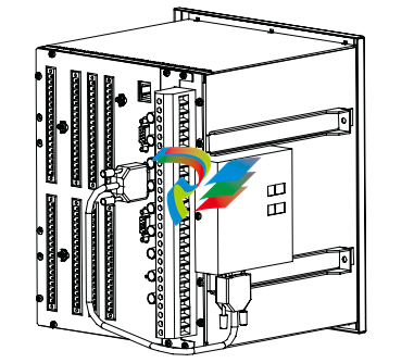
Only the cable supplied with the RER 133 may be used to connect the RER 133 module to the RE_ 54_.
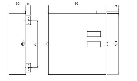
The RER 133 module consists of a printed circuit board and is housed in a metal case. Because shielded cables and an RS-485 interface is used, special attention must be paid to the grounding. The dimensions of the case are: 95 mm x 101 mm x 30 mm (95 mm x 105 mm x 38 mm with mounting bracket).
Module configuration
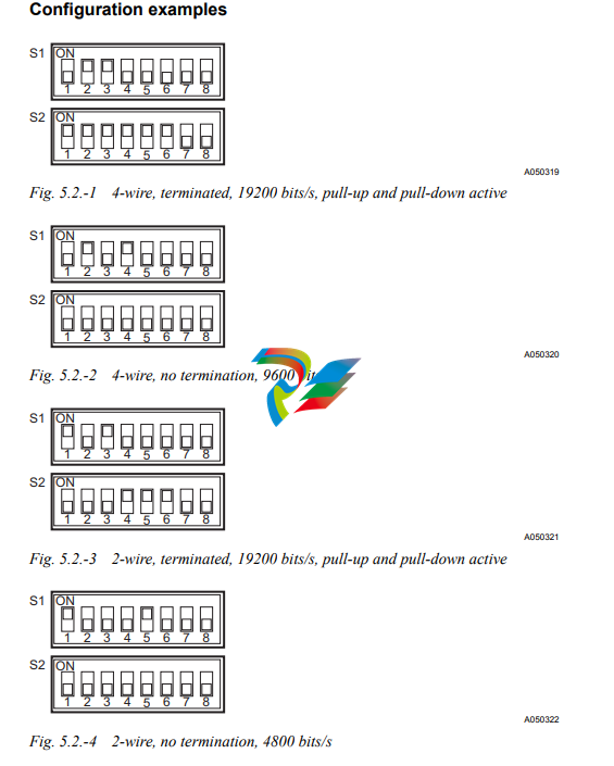
The attributes for the RER 133 can be set through the two DIP switches on the front of the module. The DIP switches are labeled S1 and S2.
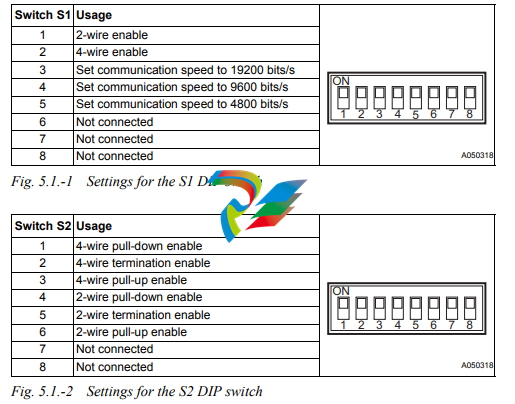
4 wire mode requires both the 2- and 4- wire switches for pull-down/ termination/pull-up to be set.
5.2. Configuration examples
Interfaces
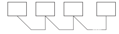
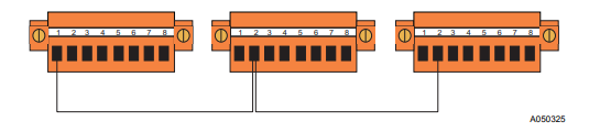
The RS-485 bus used by SPA, Modbus and DNP 3.0 requires a daisy chain topology.
A daisy chain topology means a node-to-node connection, where nodes are chained
using cables of minimal length. The cables must be point to point, no stars, rings or
other topologies are allowed. The bus must be terminated at both ends using 120Ω
resistors. The RER 133 includes as an option the use of internal termination
resistors. These resistors are enabled through DIP switch S2.
Pull-up and pull-down resistors must be used in one of the nodes, in order for the
receivers to be able to determine the state of the bus when it is idle. These resistors
can be enabled through DIP switch S2.
Please see sections ìModule configurationî on page 9 and ìConfiguration
examplesî on page 10 for the correct settings.
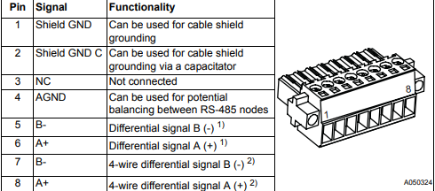
The RS-232 interface (X1) of the RER 133 module is shown in Fig. 6.-1.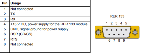
Fig. 6.-1 Pin usage table for the 9-pin D-type connector (X1) The RS-485 interface of the RER 133 module is shown in Fig. 6.-2. The connector (X2) is an 8-pin Weidm¸ller terminal block. If GND (pin 5) is used, then it is required for all other nodes to be isolated as well.
The EIA RS-485 Specification labels the data wires "A" and "B", but many manufacturers label their wires "+" and "-". In our experience, the "+" wire should be connected to the "A" line, and the "-" wire to the "B" line. When wiring RS-485 , use a shielded twisted pair cable with an internal impedance of 100-120Ω. Examples of recommended cables are CAT 5, Belden RS-485 (9841- 9844) and Alpha Wire (Alpha 6222-6230)
The shield of the cables must be directly connected to ground in one of the nodes. In the other nodes the connection should be made via a capacitor, i.e. if the shield of the cable is connected to pin 1 in node 1, all the other nodes must be grounded using pin 2.
-
 OMRON 3G3XV-A2007 3G3XV-A2007-NEV2
 -
 Omron NJ1019000 NJ1 programable logic controller
 -
 OMRON C120-LK202-EV1/C120LK202EV1
 -
 OMRON C200H-AD003 PLC
 -
 OMRON C200H-CPU23-E COIL 24VDC PLC
 -
 Omron C200HG - C200H-ID212- C200H-OC226 C200HW-BC101 PLC Base Unit
 -
 OMRON C200H-OC222(Output Unit),C200H-PS211(Power Supply Unit),SP001 Module Rack
 -
 OMRON C200H-RT201 PROGRAMMABLE CONTROLLER
 -
 OMRON C200HS-CPU01-E SYSMAC PROGRAMMABLE CONTROLLER
 -
 OMRON C200H-SNT31 C200H Programmable Controllers
 -
 OMRON C200HW-MC402-E Motion control unit
 -
 OMRON C200PC-ISA02-DRM-E PLC ISA bus compatible board card
 -
 OMRON C500-CT012 PLC
 -
 OMRON C500-NC103-E PLC
 -
 OMRON C500-NC222-E PLC
 -
 OMRON C500-PRW05-V1 PLC
 -
 OMRON C500-PRW06 PROGRAMMABLE CONTROLLER
 -
 OMRON C500-PS223-E 3G2A5-PS223-E PLC SYSMAC PROGRAMMABLE CONTROLLER
 -
 OMRON C500-TU001 3G2A5-TU001 PLC PLC
 -
 OMRON C60H-C1DR-DE-V1 Programmable Controllers
 -
 OMRON C60H-C5DR-DE-V1 Programmable Controllers
 -
 OMRON C60H-C6DR-DE-V1 Programmable Controllers
 -
 OMRON CJ1G-CPU44H CPU module
 -
 OMRON CJ1G-CPU45H PLC
 -
 OMRON CJ1M-CPU13-ETN V4.0 PLC PLC
 -
 OMRON CJ1W-AD041-V1 Analog input uni
 -
 OMRON CJ1W-CORT21 PLC module
 -
 OMRON CJ1W-IDP01 Input unit
 -
 OMRON CJ1W-MCH71 - MECHATROLINK-II
 -
 OMRON CJ1W-MD261 Digital I/O
 -
 OMRON CJ1W-NC413 Position control unit
 -
 OMRON CJ1W-NCF71 Position Control Units
 -
 OMRON CJ1W-PTS51 Process Simulation I/O Module
 -
 OMRON CJ1W-PTS52 Process Simulation I/O Module
 -
 OMRON CJ1W-SCU21-V1 PLC
 -
 Omron CJ1W-SCU22 Serial Communication Unit
 -
 OMRON CJ1W-TC001 CJ Series Temperature Control Unit
 -
 Omron CK3W-AX1515N Motion Controller
 -
 Omron CP1E-N60DR-D Compact PLC CPU
 -
 OMRON CP1E-NA20DT1-D PLC PLC
 -
 OMRON CP1H-X40DT-D plc PLC
 -
 OMRON CPM2C-S110C-DRT Interface module
 -
 OMRON CQM1-AD041 PLC
 -
 SAACKE F‑GDSA‑1 / F‑GDSA‑2 Feuerungsautomaten
 -
 SAACKE F-GDSA 143303 Controller SHIPS UPS
 -
 ICS Triplex T8270 Trusted 24 Vdc FanAssembly
 -
 SCHNEIDER M522220000 SA SM_DO16R 16 DIGITAL OUTPUTS MODULE
 -
 LENZ EPL10200-W EPZ-10203 CANPT010W3E
 -
 OMRON CQM1H-ADB21 PLC
 -
OMRON CQM1H-CPU61 PLC
-
 OMRON CQM1H-MAB42 PLC
 -
 OMRON CQM1-TC102 CQM1-TC101 PLC
 -
 OMRON CS1G-CPU44-EV1 PLC
 -
 OMRON CS1G-CPU44H CPU
 -
OMRON CS1H-CPU63-EV1 PLC
-
 OMRON CS1H-CPU66-V1 PLC
 -
 OMRON CS1W-CLK13 PLC communication module
 -
OMRON CS1W-EIP21 PLC
-
 OMRON CS1W-MAD44 PLC PLC
 -
 OMRON CS1W-SCU31-V1 CVM1-BC103 PLC
 -
 Omron CVM1-CPU21-V2 CPU Unit
 -
 OMRON F150-C10E-2 Vision Controller
 -
 OMRON F150-C15E-3 Vision Controller
 -
 OMRON F160-C15E VISION MATE CONTROLLER
 -
 OMRON F500-C10-ETN F500-C15-ETN Vision Sensor
 -
 OMRON F500-VS F500-S1
 -
 OMRON FH-3050 FH Vision Controller
 -
 Omron FQ2-S25050F PLC Smart Camera
 -
 Omron FQM1-MMA22 Motion Module
 -
 OMRON GRT1-TS2P Temperature Module
 -
 OMRON H8PR-24 Cam Positioner
 -
 OMRON IDSC-C1DR-A-E Controller
 -
 OMRON K3HB-HTA-DRT1 Temperature Panel Meter
 -
 Omron KM-N1-FLK Power Detector
 -
 OMRON CJ1G-CPU43H CPU
 -
 OMRON NA5-7W001S-V1 NA5-9W001B-V1 NA5-12W101B-V1 Graphic panel
 -
 OMRON NA5-9W001B-V1 Graphic panel
 -
 OMRON NB10W-TW01B INTERACTIVE DISPLAY
 -
 OMRON NB7W-TW01B +CP1L-EL20DR-D Complete Power Panel
 -
 OMRON NB7W-TX01B INTERACTIVE DISPLAY PLC
 -
 Omron NE1A-SCPU02 Network Controller
 -
 OMRON NA5-7W001B-V1 NA5-7W001S-V1 NA5-9W001B-V1 NA5-12W101B-V1 touch screen
 -
 Omron NS5-SQ00B-V2 NS5-SQ00-V2 NS5-SQ01-V2 NS5-SQ01B-V2 touch display panel
 -
 Omron NJ301-1100 Programmable Logic Controller
 -
 OMRON NJ501-1300 CUP Unit Programmable Controller
 -
 Omron NS12-TS01B-V2 Interactive Display
 -
 OMRON NSJW-ETN21 ETHERNET HMI
 -
 OMRON NT10S-SF121 PLC
 -
 OMRON NT20S-ST121-EV3 Touch Screen
 -
 Omron NX1P2-1140DT-BA Programmable Controller
 -
 OMRON 3G3MV-P10CDT3-E RS422/485 INVERTER BOARD
 -
 Omron C500-ID219 3G2A5-ID219 System Microprocessor
 -
 Omron PLC B7AM-8B16
 -
 OMRON PLC Module CJ1W-AD081-V1
 -
 OMRON R88D-HS10 PLC
 -
OMRON R88D-HT10 plc
-
 OMRON R88D-KN01H-ML2 Servos G5-series
 -
 OMRON R88M-H10030-B plc
 -
 OMRON R88S-H306G plc PLC
 -
 Omron Relay G9SX-GS226-T15-RT
 -
 Omron S8AS-24006N S8AS Smart Power Supply FNIP
 -
 Omron Safety Input Unit NX-SIH400
 -
 OMRON SYSMAC SCY-P1 Sequential Controller
 -
OMRON SYSMAC SCY-P0 13E Sequential Controller
-
 OMRON NS8-TV00B-V2 NS8-TV00-V2 NS8-TV00B-ECV2 NS8-TV00-ECV2 touch display Panel
 -
 Omron V680-CA5D02-V2 Programmable Controller
 -
 OMRON SGDH-04AE-OY Servo Drive
 -
OMRON SGDH-10DE-OY Servo Drive
-
 OMRON SGDS-02A12A PLC + SGMAS-C2ACA21
 -
 OMRON SGMPH-04AAA61D-OY Servo Motor
 -
 Omron ZFV-CA40 Smart Sensor Amp Unit 24VDC 0.8A
 -
OMRON ZFV-NX1 CFP0260 ZFV-A20 VISION CONTROL PANEL
-
 OMRON ZFX-C15 SMART SENSOR AMP UNIT, Vision Sensor LCD
 -
 OMRON ZFX-C20/25-CD SMART SENSOR AMP UNIT, Vision Sensor LCD
 -
 OMRON-DIGITAL TEMPERATURE CONTROLLER E5AC-CX4A5M-014 r
 -
 ABB PFVL141V-2.0MN is an industrial-grade, rectangular roll force load cell
 -
 ABB PFVL141V-1.6MN is an industrial-grade, rectangular roll force load cell
 -
ABB PFVL141V-1.25MN high-performance, rectangular roll force load cell
-
 ABB PFVL141V-1.0MN high-precision, heavy-duty rectangular load cell
 -
 ABB PFVL141V-0.8MN high-precision, heavy-duty rectangular load cell
 -
 ABB PFVL141V-0.63MN high-precision, heavy-duty rectangular load cell
 -
 GE 151X1202YE08PP08 Panel of the case / Structural component
 -
 GE 151X1212HB01MG02 Integrated LCI Controller (Old Model)
 -
 GE 151X1212GC01PC02 LCI Static Startup Controller
 -
 GE 151X1235FD01PK01 High-speed Digital Input Interface Board
 -
 GE 151X1215DK01PC01 Signal Processing / Amplification Board
 -
 GE 151X1238WP99BK01 6-pulse LCI power conversion module
 -
 GE 151X1225DF01PC03RA - Power Conversion / Drive Regulation Board


