
ABB UCU-22, UCU-23 andUCU-24control units
ABBINDUSTRIALDRIVES UCU-22, UCU-23 andUCU-24control units
Operation principle and hardware
description
Contents of this chapter
This chapter gives information about the hardware of the control units.
Hardware description
The control unit is an interface for external converter control signals, and it controls
converter modules via fiber optic links. The control unit contains a control board and
connector boards. The control unit contains integrated branching unit functionality
for collecting and storing real-time data from the converter modules to help fault
tracing and analysis. The data is stored on a memory card which can be analyzed by
ABBservice personnel.
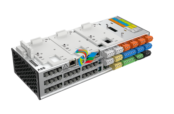
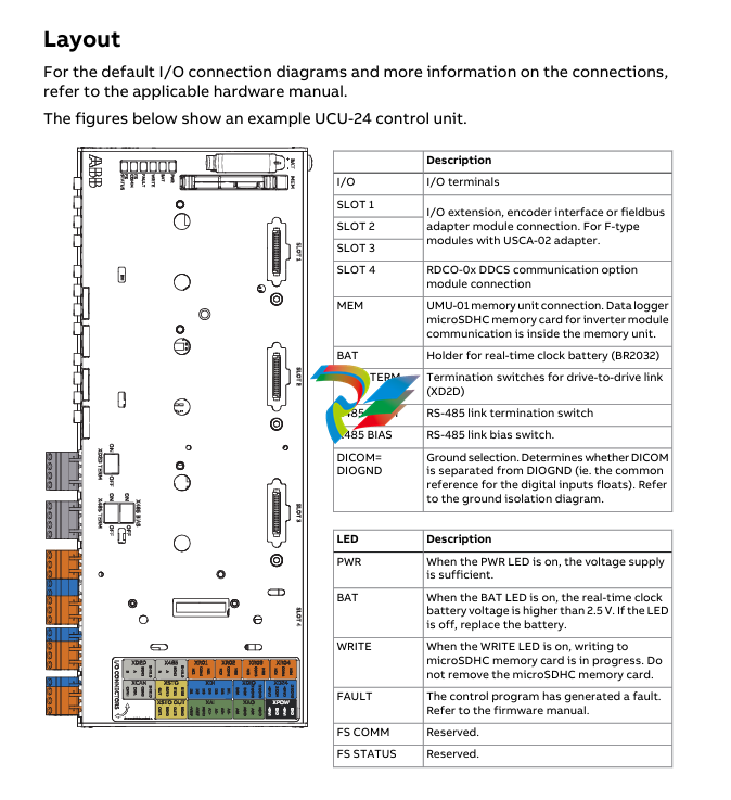
The control unit requires an external 24 V DC power source. It has three option slots
for I/O extensions, encoders and fieldbus adapters and functional safety modules,
and aremovable memoryunit. If it is necessary to replace the control unit, you can
keep the parameter settings by moving the memory unit from the defective control
unit tothenewone. ThecontrolunithasoneoptionslotforconnectingaRDCODDCS
communication option module. The control unit also has a connection for a control
panel.
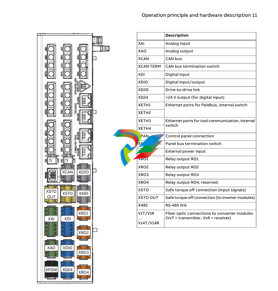
Thedrive-to-drive link (XD2D) is a daisy-chained RS-485 transmission line that allows
basic master/follower communication with one master and multiple followers. The
X485 connection provides a connection for the optional CIO-01 I/O module.
The control unit has two Ethernet ports for control network and two Ethernet ports
fortool/gatewaynetwork. Environmentalsensorsonthecontrolunitmeasurehumidity
and temperature
Contents of this chapter
This chapter gives information on the mechanical installation of the control unit and
the contents of the delivery.
Examining the delivery
Makesurethat these items are included:
• controlunitwiththeI/Oconnector plugs
• memoryunit(UMU-01)
• microSDHCflashmemorycard(insertedinitsslot inside the memory unit)
• optionslotadapters(USCA-02)
• real-timeclock battery (BR2032).
Makesurethat there are no signs of damagetotheitems.
■ Identifying different control unit types
Before you install the control unit, make sure that it has the correct control program.
The control program is shown on the label attached to the memory unit.
Makesurethat the control unit is correct for your equipment configuration
Installing the control unit onto a DIN rail
NOTICE Donotinstallthecontrol unit adjacent to electromagnetic disturbance
sources (for example, relays, contactors, brake choppers, and power cabling). The
minimumrecommendeddistancetosuchcomponentsis200mm(7.9in).ABB
recommendsthatyouinstall metallic screening between the control unit and the
source of disturbance. This can reduce the required distance.
NOTICE Makesurethataircanpassfreelythroughtheventilationholesinthecontrol
unithousing.Donotinstallthecontrolunitdirectlyaboveheat-generatingequipment.
If you do not obeythese instructions, the control unit can become too hot.
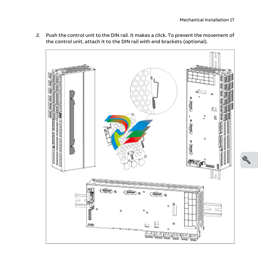
Youcaninstallthecontrolunithorizontallyorverticallyontoastandard35×7.5/15mm
DIN rail. If the control unit is installed horizontally, make sure that the connectors
point down. If the control unit is installed vertically, the connectors can point to the
left or right.
Leave sufficient free space around the control unit for:
• cabling
• cooling
• environmentalsensors
• replacingthememoryunitandreal-time clock battery.
The control unit is grounded through the DIN rail and the grounding screw.
1.
Attach thegroundingscrew(M4×6orM4×8)andwiretothecontrolunit.Ground
the control unit to the cabinet frame with the grounding wire. The minimum
cross-sectional area of the ground conductor is 4 mm2 (12 AWG)
Additional information on the connections
■ Powersupplyforthecontrol unit (XPOW)
Refer to the control unit connector data for the current and voltage ratings of the
power supply.
Connect an additional external power supply to the free +24 V and GND terminals of
the XPOWterminal block if:
• thecontrolunitmustbekeptoperationalduringinputpowerbreaks,forexample,
because of continuous fieldbus communication
• immediaterestartisnecessary after a power break (that is, no control unit
power-up delay is permitted).
■ Digital interlock (DIIL)
Digital interlock input (DIIL) terminal is originally intended for interlock signals that
stop the drive/unit when necessary. In the ACS880 primary control program, DIIL
terminal is the source for the run enable signal by default. The inverter unit or drive
cannot start, or it stops when there is no DIIL signal. In other control programs (and
units), the default use of the DIIL terminal varies. Refer to firmware manual for more
information.
Note: This input is not SIL or PL classified.
■ Control panel connection (XPAN)
The XPANconnectorcanbeusedtoconnectanassistant control panel or FDPI-02
diagnostics andpanelinterfaceunittothecontrolunit.WithFDPI-02,itispossibleto
connectonecontrolpaneltotwoormorecontrolunitsinachaintopology,alsoknown
asapanelbus.Formoreinformation,refertoFDPI-02diagnosticsandpanelinterface
user's manual (3AUA0000113618 [English]).
The XPANTERMswitchsetsthetermination for the panel bus. Must be set to ONif
thereisnopanelbus,orifthecontrolunitisthelastoneinapanelbus.Onintermediate
units in a panel bus, set termination to OFF (1).
■ TheXD2Dconnector
The XD2DconnectorhasanRS-485connection that can be usedfor
• basicmaster/follower communication with one master drive/unit and multiple
followers
• fieldbuscontrol through the embeddedfieldbus interface (EFB)
• drive-to-drive (D2D) communication implemented by application programming.
Refer to the firmware manual for the availability of these features and related
parameter settings.
Terminate the bus on the units at the ends of the drive-to-drive link. Disable bus
termination on the intermediate units.
Useashieldedtwisted-paircablefordata,andanotherpairorawireforsignalground
(nominalimpedance100…165ohm,forexampleBelden9842).Forthebestimmunity,
use high quality cable. Keep the cable as short as possible. Avoid unnecessary loops
and parallel runs near power cables such as motor cables

-
 Beckhoff CX2500-B310 | Fieldbus slave module PROFIBUS for CX20xx, CX52x0. CX53x0. CX56x0
 -
 Beckhoff CX2500-0070 | USB 3.0 module for CX20xx, CX52xx, CX53x0. CX56x0
 -
 Beckhoff CX2500-0062 | 2.5 Gbit Ethernet module for CX20xx, CX52x0. CX53x0. CX56x0
 -
 Beckhoff CX2500-1061 | Power over Ethernet module for CX20xx, CX52x0. CX53x0. CX56x0
 -
 Beckhoff CX2500-1060 | Ethernet module for CX20xx, CX52x0. CX53x0. CX56x0
 -
 Beckhoff CX2500-0031 | Serial Interface RS485/RS422 for CX20xx, CX52x0. CX53x0. CX56x0
 -
 Beckhoff CX2500-0030 | Serial Interface RS232 for CX20xx, CX52x0. CX53x0. CX56x0
 -
 Beckhoff CX5230-0195 CPU module
 -
Beckhoff CX5230-0190 CPU module
-
Beckhoff CX5230-0175 CPU module,
-
Beckhoff CX5230-0170 CPU module
-
Beckhoff CX5230-0100 CPU module, no operating system, no TwinCAT
-
 Beckhoff CU8130-0240 | UPS modul, battery-backed
 -
 Beckhoff CU8130-0120 | UPS module, battery-backed
 -
 Beckhoff CU8110-0120 | UPS module, capacitive
 -
 Beckhoff CU8110-0060 | UPS module, capacitive
 -
 Beckhoff CX5130-0195 CPU module
 -
 Beckhoff CX5130-0190 CPU module
 -
Beckhoff CX5130-0185 CPU module
-
Beckhoff CX5130-0170 CPU module, Microsoft Windows 10 IoT Enterprise 2019 LTSC
-
Beckhoff CX5130-0163 CPU module
-
Beckhoff CX5130-0162 CPU module
-
 Beckhoff CX5130-0161 CPU module
 -
Beckhoff CX5130-0160 CPU module
-
Beckhoff CX5130-0155 CPU module
-
Beckhoff CX5130-0150 CPU module
-
Beckhoff CX5130-0143 CPU module
-
Beckhoff CX5130-0142 CPU module
-
Beckhoff CX5130-0140 CPU module
-
Beckhoff CX5130-0135 CPU module
-
Beckhoff CX5130-0130 CPU module
-
Beckhoff CX5130-0125 CPU module
-
 Beckhoff CX5130-0123 CPU module
 -
Beckhoff CX5130-0122 CPU module
-
Beckhoff CX5130-0121 CPU module
-
 Beckhoff CX5130-0115 CPU module
 -
Beckhoff CX5130-0113 CPU module
-
Beckhoff CX5130-0112 CPU module
-
Beckhoff CX5130-0111 CPU module
-
Beckhoff CX5130-0110 CPU module, Microsoft Windows Embedded Compact 7. no TwinCAT
-
Beckhoff CX5130-0100 CPU module, no operating system, no TwinCAT
-
 DEIF FAS-113DG Synchronisation & circuit breaker closing
 -
 DEIF FAS-115DG Synchronisation & circuit breaker closing
 -
 DEIF HAS-111DG Synchronisation & circuit breaker closing
 -
 DEIF LSU-122DG Load sharing, paralleling & operation
 -
 DEIF LSU-114DG Load sharing, paralleling & operation
 -
 DEIF LSU-113DG Load sharing, paralleling & operation
 -
 DEIF LSU-112DG Load sharing, paralleling & operation
 -
 DEIF RMF-112D Frequency relay
 -
 DEIF RMC-142D Current relay
 -
 DEIF RMC-132D Current relay
 -
 DEIF RMC-131D Current relay
 -
 DEIF RMC-122D Current relay
 -
 DEIF RMC-121D Current relay
 -
 DEIF RMC-111D Current relay
 -
 DEIF MVR-V211 Busbar Protection
 -
 DEIF MVR-T257 Transformer Differential Protection
 -
 DEIF MVR-T256 Transformer Differential Protection
 -
 DEIF MVR-T216 Transformer Differential Protection
 -
DEIF MVR-T215 Transformer Protection
-
 DEIF MVR-M257 Motor Differential Protection
 -
 DEIF MVR-M255 Motor Protection
 -
 DEIF MVR-M215 Motor Protection
 -
 DEIF MVR-M210 Motor Protection
 -
 DEIF MVR-G257 Generator Differential Protection
 -
 DEIF MVR-G215 Generator Protection
 -
 DEIF MVR-F255 Directional Feeder Protection
 -
 DEIF MVR-F215 Directional Feeder Protection
 -
DEIF MVR-F210 Feeder Protection
-
 DEIF MVR-F205 Directional Feeder Protection
 -
 DEIF MVR-F201 Basic Feeder Protection
 -
DEIF MVR-200 series Medium Voltage Relay
-
 DEIF MDR-2 Multi-differential relay
 -
 DEIF LMR-122D Loss of mains relay
 -
 DEIF LMR-111D Loss of mains relay
 -
 DEIF APU-4 Advanced G59 and G99 protection unit
 -
 DEIF iE 650 PLC - The most robust programmable automation controller available
 -
 DEIF iE 350 PLC - Programmable Automation PLC Controller
 -
 DEIF iE 250 PLC Versatile and modular intelligent energy PLC controller
 -
 DEIF PPM-3 EDG Protection and Power Management
 -
 DEIF AGC 3X 4198000234E AUTOMATIC GENSET CONTROLLER
 -
 SAUTER ASF123 Damper actuator with spring return
 -
SAUTER ASF122 Damper actuator with spring return
-
SAUTER ASF113F122 Damper actuator with spring return
-
SAUTER ASF113F120 Damper actuator with spring return
-
SAUTER ASF112F122 Damper actuator with spring return
-
SAUTER ASF112F120 Damper actuator with spring return
-
 SAUTER ASM 124/134 series - ASM134F130 Damper actuator
 -
SAUTER ASM 134 series - ASM134SF132 Damper actuator
-
SAUTER ASM 124/134 series - ASM124SF132 Damper actuator
-
SAUTER ASM 124/134 series - ASM124F122 Damper actuator
-
SAUTER ASM 124/134 series - ASM124F120 Damper actuator
-
 SAUTER Valve actuator ASM 105S/115S series ASM115SF152
 -
SAUTER Valve actuator ASM 105S/115S series ASM105SF152
-
SAUTER Valve actuator ASM 105S/115S series ASM115SF132
-
SAUTER Valve actuator ASM 105/115 series ASM105SF132
-
 SAUTER Valve actuator ASM 105/115 series ASM115F122
 -
SAUTER Valve actuator ASM 105/115 series ASM115F120
-
SAUTER Valve actuator ASM 105/115 series ASM105F122
-
SAUTER Valve actuator ASM 105/115 series ASM105F120
-
SAUTER Valve actuator ASM 105/115 series ASM105F10
-
 SAUTER AKF113S Rotating actuator AKF 112/113 series
 -
SAUTER AKF113F122 Rotating actuator AKF 112/113 series
-
SAUTER AKF113F120 Rotating actuator AKF 112/113 series
-
SAUTER AKF112F122 Rotating actuator AKF 112/113 series
-
SAUTER AKF112F120 Rotating actuator AKF 112/113 series
-
 SAUTER AKM115SAF332: Smart Actuator for ball valve, BACnet/IP
 -
 SAUTER AKM115SAF232 Rotating Actuator AKM 115SA Smart Actuator
 -
 SAUTER AKM115SF152 Rotating Actuator AKM 105S/115S Series
 -
SAUTER AKM115SF132 Rotating Actuator AKM 105S/115S Series
-
SAUTER AKM105SF132 Rotating Actuator AKM 105S/115S Series
-
 SAUTER AKM115F122 Rotating actuator AKM 105/115 series
 -
 SAUTER Rotating actuator AKM 105/115 series AKM115F120
 -
SAUTER Rotating actuator AKM 105/115 series AKM105F122
-
SAUTER Rotating actuator AKM 105/115 series AKM105F120
-
 SAUTER Continuous actuator for unit valves, with stroke AXS215S
 -
 SAUTER Linear valve actuator AXT/AXS series AXT211
 -
SAUTER Linear valve actuator AXT/AXS series AXT201
-
 SAUTER Linear valve actuator AXM/AXF series AXF217S
 -
SAUTER Linear valve actuator AXM/AXF series AXM217S
-
SAUTER AXM217SF404 is an electric actuator for unit valves.
-
SAUTER AXM217SF402 is an electric actuator for unit valves.
-
SAUTER Linear valve actuator AXM/AXF series AXM217
-
 SAUTER Linear valve actuator AVF 124/125 series AVF125S
 -
SAUTER Linear valve actuator AVF 124/125 series AVF124S
-
SAUTER Linear valve actuator AVF 124/125 series AVF124S
-
 SAUTER AVM322S-R Linear valve actuator AVM 234S series
 -
SAUTER AVM322-R Linear valve actuator AVM 234S series



