DEIF LSU-113DG Load sharing, paralleling & operation
LSU-113DG
Load sharing, paralleling & operation
DEIF's load sharing units offer load sharing in various ways between generators and interfaces to a governor through an electronic potentiometer (EPQ96-2 or EPN110DN).
DEIF’s load sharing units offer load sharing in various ways between generators and interfaces to a governor through an electronic potentiometer (EPQ96-2 or EPN110DN).
Suitable for control of diesel and gas generators, for instance, they can control the power unit in stand-alone mode (performing frequency control) or parallel with other power units (performing frequency and power control).
The units have built-in power and frequency transducers that enable connection of external equipment. Constant power or isochronous mode is also possible. Speed control is conducted by two relays.
Variants
LSU-112DG
Frequency and power control
LSU-113DG
Frequency and power control
With -P>
LSU-114DG
Frequency and power control
With start/stop
LSU-122DG
Reactive
U and Q control
Features
Frequency and power control. With -P>
Built-in power and frequency transducer
Constant power or isochronous mode
LED indication of status
LED indication for activated control
35 mm DIN rail or base mountin
Terminal no. Description/action
1 and 3
X1/X2
Input for supply voltage.
17 and 18
Sta
Status output, activated (closed) when the supply voltage is connected and the unit is working correctly.
28 and 29
IL1
Input for the current measurement. Note that S1 on the external current transformer is connected to
terminal 28. and S2 is connected to terminal 29.
31 and 32
Ext. P.
Must be short-circuited, if the internal power transducer is used (normal). For applications with unbal
anced load it is recommended to use an external power transducer (replacing the built-in one). Connect
external power transducer to 31 (+) and 32 (-). The output of the external transducer must be 4 to 20 mA
DC. The output of the connected transducer must limit the output to min. 2 mA and max. 22 mA. DEIF
transducer type TAS-331DG is recommended.
33 and 34

(“Unl”)
May be connected to a potential-free N/O relay contact. When this contact is activated, the power of the
generator is regulated to zero (unloading) and the LSU-112DG is disconnected from the PS power line.
35
(“Ref.”)
Reference input. Must be connected to term. 36 (“”), if not used. This input is used to control the power
unit running in power control mode (fixed load to grid). A +0.5 V to 5 V connected to the input with re
spect to will control the PU in the range 10 to 100 % power. The input activates at 0.55 V and deac
tivates at 0.45 V. Please notice that when this input is active the LSU-112DG is still connected to the PS
and FS lines. In this mode the PS line acts only as an output.
37
(“+5V”)
Reference output. This voltage output can be used for local power control mode. If terminal 37 is feeding
a voltage divider, and the output from the voltage divider is connected to terminal 35. local power control
can be performed.
36
(“”)
Common earth terminal for the above reference input/output.
38 (FS) and
39 (“”)
Paralleling line for frequency sharing of the connected LSU-112DGs.
40 (PS) and
41 (“”)
Paralleling line for power sharing of the connected LSU-112DGs. Normally 5 V at nominal busbar volt
age and cos phi = 1. If cos phi 0.8 is stated on the label, 4 V correspond to 100 % power.
43 and 44
Relay con
tacts “SG”
Relay contact for increase of the speed.
45 and 46
Relay con
tacts “SG”
Relay contact for decrease of the speed.
NOTE:
Relay
contacts
Relays (SG) should always be connected via external auxiliary relays when a DC pilot motor is applied.
A transient suppressor should always be connected across the relay coil of the external relays.
NOTE:
All terminals marked “” are internally connected.
For correct function of the LSU-112DG any analogue DC input must not exceed 110 % of its nominal value. To ensure
correct power measurement it is important that the AC current input does not exceed 110 % of its nominal value. To
accomplish this it is important to take the value of the max. cos phi into consideration when ordering/configuring the LSU
112DG, for example by using the kVA figure of the generator and cos phi = 1.
| User name | Member Level | Quantity | Specification | Purchase Date |
|---|



-
 SELSEL-T401L Ultra-High-Speed Line Relay
-
 SEL SEL-T400L Time-Domain Line Protection
-
 SEL SEL-2664S Stator Ground Protection Relay
-
 SEL SEL-787-2/-3/-4 Transformer Protection Relay
-
 SEL SEL-787 Transformer Protection Relay
-
 SEL SEL-751 Feeder Protection Relay
-
 SEL SEL-700G Generator Protection Relay
-
 SEL-487E Transformer Protection Relay
-
 SEL-400G Advanced Generator Protection System
-
 SEL SEL-387E Current Differential and Voltage Relay
-
 SEL SEL-387A Current Differential and Overcurrent Relay
-
 SEL SEL-387 Current Differential and Overcurrent Relay
-
 SEL SEL-300G Generator Relay
-
 SEL SEL-700BT Motor Bus Transfer Relay
-
 CTI 2500 Series® Slice Ethernet Remote I/O System
-
 CTI 2500 Series® Compact Programmable Automation Control System
-
 CTI 2500 Series® Classic Programmable Automation Control System
-
 CTI 2500 Series® Bases
-
 SHINKAWA VM-25 Condition Monitoring System UPDATED
-
 SHINKAWA VM-5 SERIES OPTIONS
-
 ABB SACO 64D4 Annunciator unit
-
 ABB SPAU 140 C Synchro-check relay
-
 EATON Instructions for the FP-5000
-
 HONEYWELL TDC 3000X Advanced Process Manager
-
 HONEYWELL ENHANCED MICRO TDC 3000
-
 VIBRO-METER VM600Mk2/ VM600 RPS6U rack power supplies
-
 VIBRO-METER VM600Mk2/ VM600 ABE056 slimline rack
-
 VIBRO-METER VM600Mk2 RLC16Mk2 relay modules
-
 VIBRO-METER VM600Mk2 MPC4Mk2 + IOC4Mk2 machinery protection and condition monitoring modules
-
 VIBRO-METER VM600Mk2 CPUMMk2 + IOCNMk2 rack controller and communications interface module
-
 VIBRO-METER VM600Mk2 CPUMMk2 + IOCNMk2 rack controller and communications interface module
-
 ADLINK PCI/PCIe-7300A, cPCI-7300 32-CH 80 MB/s High-Speed Digital I/O Cards
-
 ADLINK cPCI-7248/7249R 48-CH DIO & Timer/Counter Cards
-
 ADLINK PCI-7230/7233/7234. LPCI/LPCIe/cPCI-7230 32-CH Isolated DIO Cards
-
 ADLINK cPCI-6965 Series Value 6U CompactPCI® Intel® Core™2 Duo
-
 ADLINK cPCI-6910 Series 6U CompactPCI® Dual-Core Intel® Xeon® Processor LV / ULV Universal Blade
-
 ADLINK CPCI-6670 6U CompactPCI Low Power Pentium® III SBC
-
 ADLINK cPCI-6625/6 Series 6U CompactPCI® PlusIO blade with Intel® Core™ i7/i3 Processor
-
 ADLINK 3U CompactPCI CPU Modules
-
 ADLINK CM-435 Extreme Rugged™ PC/104 Single Board Computer
-
 ADLINK PCI-8254/8258 DSP-based 4/8-axis Advanced Motion Controllers
-
 ADLINK NuPRO-E43 PICMG® 1.3 Full-Size LGA1151 with 6th/7th Generation Intel® Core™ i7/i5/i3
-
 ADLINK DLAP-211-JNX/DLAP-211-JT2/ DLAP-211-Nano
-
 Hirschmann RS30-1602O6O6SDAE compact OpenRail managed Ethernet switches
-
Hirschmann RS30-0802O6O6SDAE Ethernet switch
-
 Hirschmann RS20-1600T1T1SDAE Management-type Ethernet switch
-
 Hirschmann OCTOPUS 24M Limited Availability/Passive
-
 Hirschmann MSP30-24040SCZ9MRHHE3A
-
 Hirschmann MAR1040-4C4C4C4C9999SMMHRHHXX.X. Gigabit Ethernet Switch configurator
-
 Hirschmann Industrial Ethernet Rail Switch SPIDER II, SPIDER II Giga, SPIDER II PoE
-
 Hirschmann Industrial Ethernet Firewall EAGLE One
-
 Hirschmann Industrial Security Router EAGLE20/30
-
 Hirschmann Description and operating instructions RS2-xTX/xFX EEC
-
 Basler Electric DECS-200 Digital Excitation Control System
-
 Basler Electric GENERATOR PROTECTION SYSTEM BE1-GPS100
-
 Jaquet FT3000 Speed measurement system
-
 Hirschmann Industrial Ethernet Ruggedized Switch MACH1000 Family
-
 Basler Electric BESTCOMSPlus®
-
 ETEL AccurET MODULAR 300 EA-P2M-300-xxxxxA controller
-
 Basler Electric ES Series Protection Relays
-
 ABB Multifunction Protection and Switchbay Control Unit REF542plus
-
 EMERSON AMS 2140 Machinery Health Analyzer
-
 Hirschmann Industrial Ethernet Rail Switch RS20 Basic Family
-
 GE Grid Solutions P40U Px40 USB Adaptor
-
 ABB ontinuous Gas Analyzers AO2000 Series AO2040CU Ex Central Unit in Category 2G
-
 ABB Advance Optima AO2000 Series Continuous gas analyzers Models AO2020. AO2040
-
 Advance Optima Module Uras 14
-
 SAACKE control optimization
-
 SAACKE se@vis efficiency monitor
-
 SAACKE se@vis pro
-
 SAACKE se@vis eco
-
 SAACKE se@vis compact
-
 HIRSCHMANN Industrial ETHERNET Switch MICE MS20/MS30
-
 HIRSCHMANN MICE Media modules
-
 Kongsberg GL-10 Level Switch
-
 B&R ACOPOSinverter P74 frequency converter
-
 Beckhoff CX2020 | Basic CPU module (service phase)
-
 Beckhoff CX1010 | Basic CPU module (service phase)
-
 Beckhoff CX5120 | Embedded PC with Intel Atom® E3815
-
 Beckhoff CP69xx-xxxx-0010 | Economy built-in Control Panel with DVI/USB Extended interface
-
 Beckhoff CP29xx-0000 | Multi-touch built-in Control Panel with DVI/USB Extended interface
-
 SAACKE Monoblock Rotary Cup Burner SKVJ-M
-
 ABB Plantguard Fault Tolerant Technology Architecture and Software
-
 OMRON H8PR-8/H8PR-8P H8PR-16/H8PR-16P H8PR-24/H8PR-24P Rotary Positioner
-
 ABB PFSA107-Z42 DTU Stressometer Digital Transmission Unit
-
 Nidec Mentor MP
-
 IBA ibaNet-E
-
 IBA FO Connection to Reflective Memory
-
 IBA FO Connection to Siemens Systems
-
 IBA Interface Cards For Fiber Optic Connections
-
 IBA Field and Drive Buses
-
 IBA ibaPADU-S Modular System
-
 IBA ibaMAQS
-
 STUCKE SYMAP®ARC
-
 STUCKE SYMAP®R
-
 STUCKE SYMAP®Compact
-
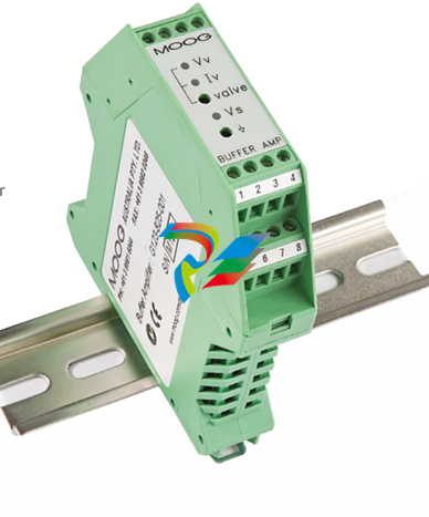 MOOG G123-825-001 BUFFER AMPLIFIER
-
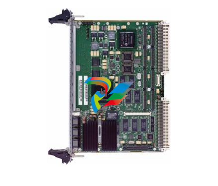 Motorola MVME5100 Series VME Processor Modules
-
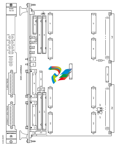 Motorola MVME162 Embedded Controller
-
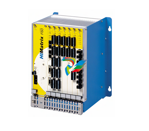 HIMatrix Safety-Related Controller System Manual for the Modular Systems
-
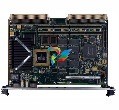 Motorola MVME2400 Series VME Processor Module
-
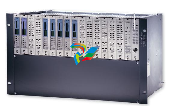 Sieger System 57
-
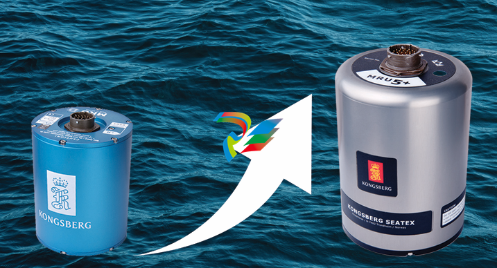 KONGSBERG MRU product line continuation
-
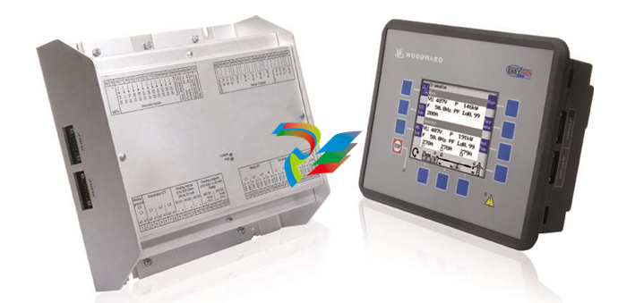 Woodward easYgen-3100/3200 Genset Control for Multiple Unit Operation
-
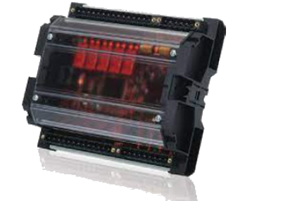 Woodward MFR 300 Multifunction Relay / Measuring
-
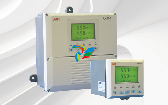 ABB AX410, AX411, AX413, AX416, AX418, AX450, AX455 and AX456 Single and dual input analyzers for low level conductivity
-
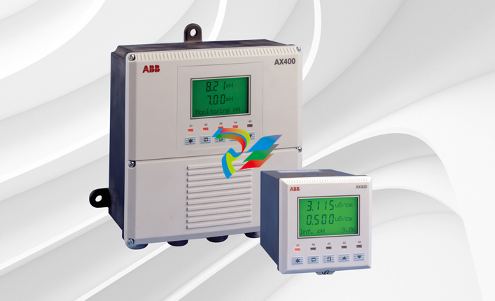 ABB AX410, AX411, AX416, AX450 and AX455 Single and dual input analyzers
-
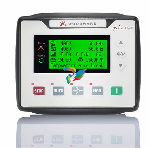 Woodward easYgen-1400 Technical Manual Genset Control
-
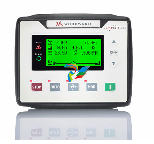 Woodward easYgen-400 Operation Manual Genset Control
-
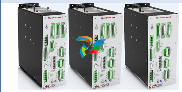 Woodward High Output Digital Valve Positioner (DVP)DVP5000/DVP10000/DVP12000
-
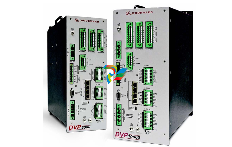 Woodward High Output Digital Valve Positioner DVP5000 and DVP10000
-
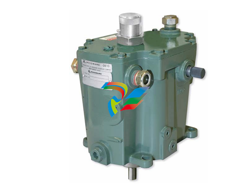 Woodward TG611-13/-17 Overspeed Test Device Conversion Kit
-
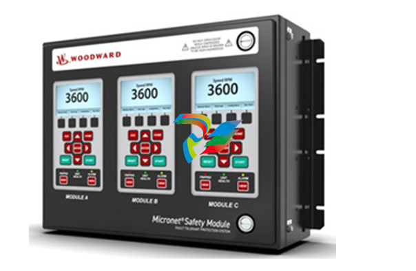 Woodward MicroNet Safety Module (MSM)
-
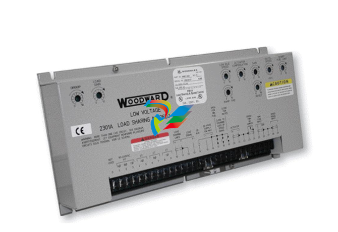 Woodward 2301A Electronic Load Sharing and Speed Control 9905/9907 Series
-
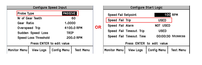 Woodward-Service Bulletin 01671
-
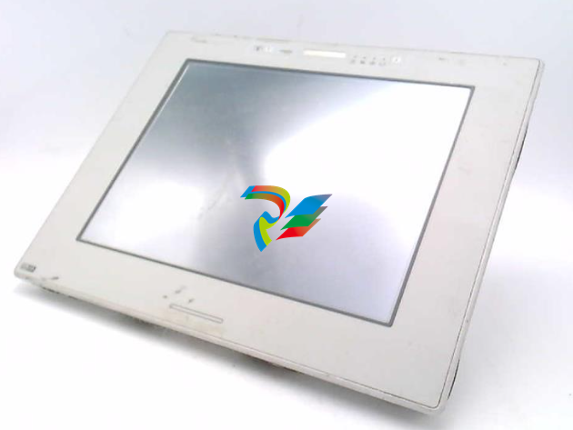 UniOP eTOP40B 12.1” TFT color display
-
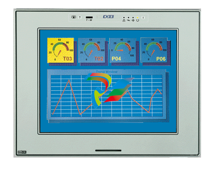 UniOP eTOP40 TFT Color display
-
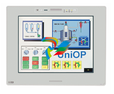 UniOP eTOP33B 10.4” TFT color display
-
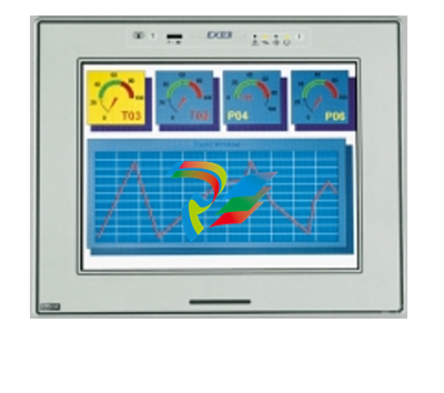 UniOP eTOP33C eTOP33-0050 Resistive touchscreen
-
UniOP eTOP30. eTOP32 eTOP32-0050 Human-machine interface equipment
-
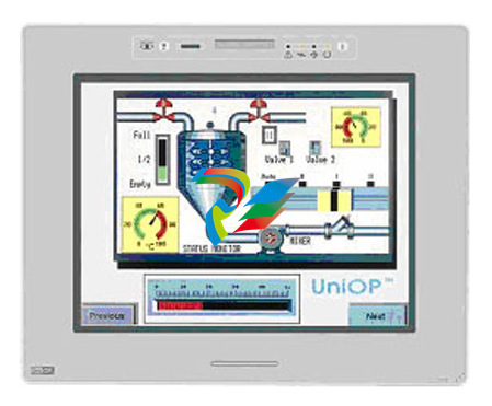 UniOP eTOP20B and eTOP21B eTOP20B-0050
-
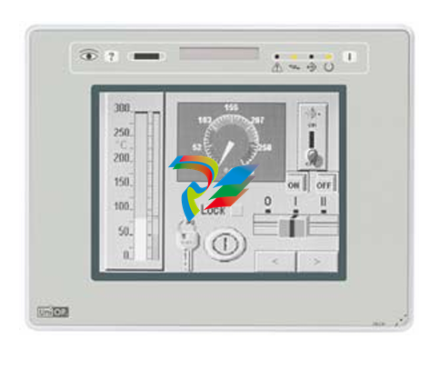 UniOP eTOP12 eTOP12-0050 Advanced human-machine interface equipment
-
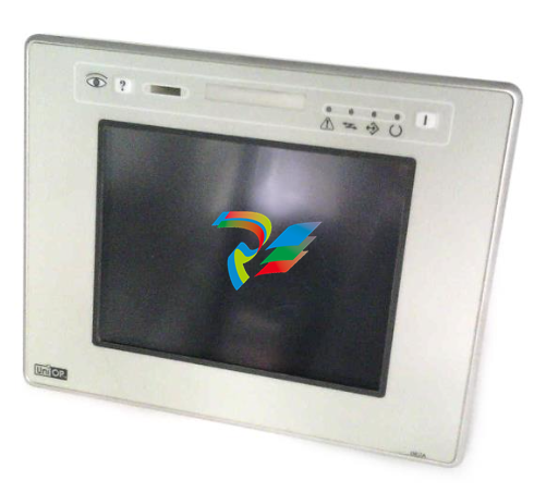 UniOP eTOP11 eTOP11-0050 HMI
-
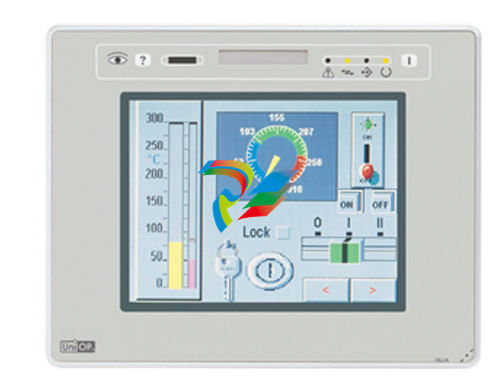 UniOP eTOP06C HMI
-
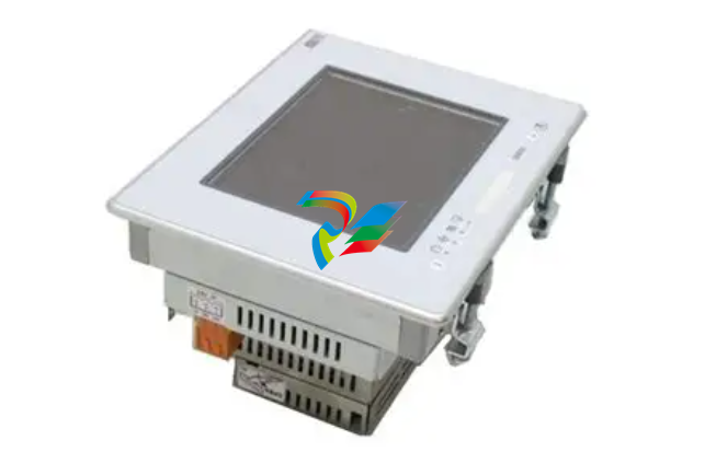 UniOP eTOP06 HMI
-
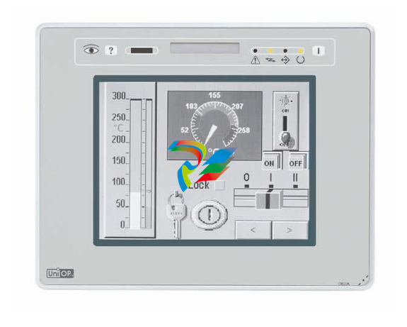 UniOP eTOP05EB eTOP05EB-DF45 HMI
-
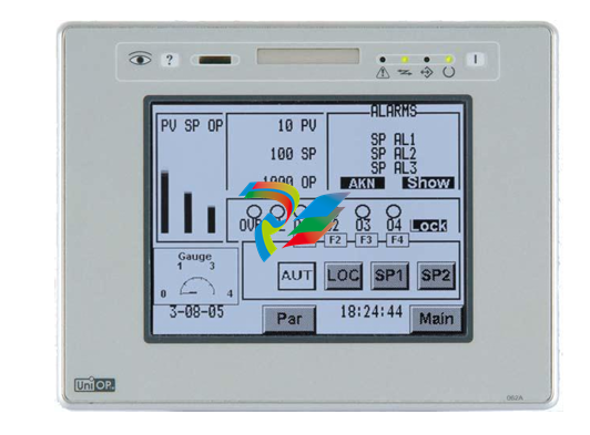 UniOP eTOP05. eTOP05P Human-machine interface equipment
-
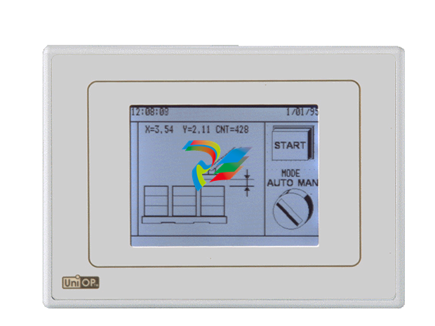 UniOP eTOP03 eTOP03-0046