
SAUTER Linear valve actuator AVM 234S series AVM234SF132
AVM 234S: SUT valve actuator with positioner
How energy efficiency is improved
Automatic adaptation to valve, precision activation and high energy efficiency with minimal operating
noise
Features
• Activation of 2-way and 3-way valves of the VQD/BQD and VQE/BQE series, as well as VUG/BUG,
VUS/BUS, VUP, V6R/B6R and VDL
• For controllers with constant output (0...10 V or 4...20 mA) or switching output (2-point or 3-point
control)
• Stepping motor with SAUTER Universal Technology (SUT) electronic control unit and electronic,
force-dependent cut-off
• Simple assembly with valve; spindle is automatically connected after control voltage is applied
(patented system)
• Automatic detection of applied control signal (constant or switched); indicated by two LEDs
• Coding switches for selecting characteristic and running time
• Type of characteristic (linear/quadratic/equal-percentage) can be set on the actuator
• Automatic adaptation to the stroke of the valve (min. valve stroke 8 mm, max. valve stroke 49 mm).
The measured stroke is saved and is not lost even in the event of a power failure
• Direction of operation can be selected via screw terminals when making the electrical connection
• Crank handle for external manual adjustment with motor cut-off and as trigger for a re-initialisation
• Numerous adapters enable the unit to be fitted onto non-SAUTER valves
• Power supply 230 V with module or direct connection for 24 VAC / 24 VDC; continuous activation
also admissible with 230 V
•Maintenance-free gear unit made of sintered steel; gearbox base-plate made of steel
•Mounting column made of stainless steel; mounting bracket made of cast light alloy for fitting the
valve

• Electrical connections (max. 2.5 mm²) with screw terminals
• Three pre-scored cable inlets for M20 × 1.5 (2×) and M16 × 1.5
• Fitting vertically upright to horizontal, not suspended
Connection with 230 V or 100…110 V as 2-point/3-point or with continuous activation of valve
actuator (accessory 0372332)
The built-in positioner controls the actuator depending on controller’s output signal y.
A voltage signal (0...10 V–) at terminal 3u or a current signal at terminal 3i serves as the control
signal. If there is a control signal on both terminals (3u (0...10 V) and 3i (4...20 mA)) at the same time,
the input with the higher value has priority.
Direction of operation 1 (mains power supply on internal connection 2a):
When the positioning signal is increasing, the actuator spindle extends.
Direction of operation 2 (mains power supply on internal connection 2b):
When the positioning signal is increasing, the actuator spindle retracts.
The starting point and control span are fixed. A split-range unit (only for voltage input 3u) designed for
installation in the actuator is available as an accessory for adjusting partial ranges (see split-range
unit function).
After the connection of the power supply and the initialisation, the actuator moves to every valve
stroke between 0% and 100%, depending on the control signal. Thanks to the electronics and the
travel measurement system, no stroke is lost, and the actuator does not require periodic re
initialisation. When the end positions are reached, this position is checked, corrected if necessary,
and saved again. It is thus possible to operate multiple actuators of the SUT type in parallel. The
feedback signal y0 = 0...10 V corresponds to the effective valve stroke of 0...100 %.
If the control signal 0...10 V or 4...20 mA is interrupted with direction of operation 1. the actuator
spindle moves in completely, or moves out completely with direction of operation 2.
The coding switch can be used to set the characteristic of the valve. An equal-percentage or
quadratic characteristic can only be generated when the actuator is used as a continuous actuator.
Additional switches can be used to select the running times (with the 2-point, 3-point or continuous
functions).
Continuous actuation can also be used with a power supply of 230 V or 110 V (accessory required).
You must ensure that the neutral wire of the controller is connected to the control voltage. The neutral
wire of the power supply may only be used for the module.
LED indicator: The indicator consists of bi-colour LEDs (red/green).
Both LEDs flash red
Top LED lights up red
Bottom LED lights up red
Top LED flashes green
Top LED lights up green
Initialisation
Top limit stop or “CLOSED” position reached
Bottom limit stop or “OPEN” position reached
Actuator is running, moving to “CLOSED” position
Actuator is stopped, last direction of travel “CLOSED”
Bottom LED flashes green
Bottom LED lights up green
No LED lights up
Both LEDs flash red and green
Actuator is running, moving to “OPEN” position
Actuator is stopped, last direction of travel “OPEN”
No power supply (terminal 2a or 2b)
Actuator is in manual mode
| Bently Nevada | 3500/22M-01-01-01 |
| Alstom | UT150-2 |
| EMERSON | PR6423 009-041+CON 041/913-030 |
| Honeywell | HCIX15-TE-FA-NC |
| KEBA | D3-DU 360/A-2100-20 |
| SARTORIUS | MDB-8E |
| ALSTOM | ALSPA CE 80-20 |
| ALSTOM | Test PLUG MMLB01 |
| Rolls-Royce | ACP-04S19-002 |
| ABB | REM545BG227AAAB |
| EPRO | PR9376/010-011+CON021 |
| Rolls-Royce - | ACP-04S12-001 20095201 |
| ABB | RET 670*2.0-A40X00 Order = 4202183240-130 Ordering no: 1MRK004816-CE |
| MOOG | 6+PE B97007 |
| YOKOGAWA | GC8000 |
| IFS | IFS DE7210M |
| EXPO | ETM-IS31-001 |
| ABB | AC10272001R0101 5SXE10-0181 |
| Kawasaki | C-B10-A100-21 |
| User name | Member Level | Quantity | Specification | Purchase Date |
|---|



-
 CTI 2500 Series® Slice Ethernet Remote I/O System
 -
 CTI 2500 Series® Compact Programmable Automation Control System
 -
 CTI 2500 Series® Classic Programmable Automation Control System
 -
 CTI 2500 Series® Bases
 -
 SHINKAWA VM-25 Condition Monitoring System UPDATED
 -
 SHINKAWA VM-5 SERIES OPTIONS
 -
 ABB SACO 64D4 Annunciator unit
 -
 ABB SPAU 140 C Synchro-check relay
 -
 EATON Instructions for the FP-5000
 -
 HONEYWELL TDC 3000X Advanced Process Manager
 -
 HONEYWELL ENHANCED MICRO TDC 3000
 -
 VIBRO-METER VM600Mk2/ VM600 RPS6U rack power supplies
 -
 VIBRO-METER VM600Mk2/ VM600 ABE056 slimline rack
 -
 VIBRO-METER VM600Mk2 RLC16Mk2 relay modules
 -
 VIBRO-METER VM600Mk2 MPC4Mk2 + IOC4Mk2 machinery protection and condition monitoring modules
 -
 VIBRO-METER VM600Mk2 CPUMMk2 + IOCNMk2 rack controller and communications interface module
 -
 VIBRO-METER VM600Mk2 CPUMMk2 + IOCNMk2 rack controller and communications interface module
 -
 ADLINK PCI/PCIe-7300A, cPCI-7300 32-CH 80 MB/s High-Speed Digital I/O Cards
 -
 ADLINK cPCI-7248/7249R 48-CH DIO & Timer/Counter Cards
 -
 ADLINK PCI-7230/7233/7234. LPCI/LPCIe/cPCI-7230 32-CH Isolated DIO Cards
 -
 ADLINK cPCI-6965 Series Value 6U CompactPCI® Intel® Core™2 Duo
 -
 ADLINK cPCI-6910 Series 6U CompactPCI® Dual-Core Intel® Xeon® Processor LV / ULV Universal Blade
 -
 ADLINK CPCI-6670 6U CompactPCI Low Power Pentium® III SBC
 -
 ADLINK cPCI-6625/6 Series 6U CompactPCI® PlusIO blade with Intel® Core™ i7/i3 Processor
 -
 ADLINK 3U CompactPCI CPU Modules
 -
 ADLINK CM-435 Extreme Rugged™ PC/104 Single Board Computer
 -
 ADLINK PCI-8254/8258 DSP-based 4/8-axis Advanced Motion Controllers
 -
 ADLINK NuPRO-E43 PICMG® 1.3 Full-Size LGA1151 with 6th/7th Generation Intel® Core™ i7/i5/i3
 -
 ADLINK DLAP-211-JNX/DLAP-211-JT2/ DLAP-211-Nano
 -
 Hirschmann RS30-1602O6O6SDAE compact OpenRail managed Ethernet switches
 -
Hirschmann RS30-0802O6O6SDAE Ethernet switch
-
 Hirschmann RS20-1600T1T1SDAE Management-type Ethernet switch
 -
 Hirschmann OCTOPUS 24M Limited Availability/Passive
 -
 Hirschmann MSP30-24040SCZ9MRHHE3A
 -
 Hirschmann MAR1040-4C4C4C4C9999SMMHRHHXX.X. Gigabit Ethernet Switch configurator
 -
 Hirschmann Industrial Ethernet Rail Switch SPIDER II, SPIDER II Giga, SPIDER II PoE
 -
 Hirschmann Industrial Ethernet Firewall EAGLE One
 -
 Hirschmann Industrial Security Router EAGLE20/30
 -
 Hirschmann Description and operating instructions RS2-xTX/xFX EEC
 -
 Basler Electric DECS-200 Digital Excitation Control System
 -
 Basler Electric GENERATOR PROTECTION SYSTEM BE1-GPS100
 -
 Jaquet FT3000 Speed measurement system
 -
 Hirschmann Industrial Ethernet Ruggedized Switch MACH1000 Family
 -
 Basler Electric BESTCOMSPlus®
 -
 ETEL AccurET MODULAR 300 EA-P2M-300-xxxxxA controller
 -
 Basler Electric ES Series Protection Relays
 -
 ABB Multifunction Protection and Switchbay Control Unit REF542plus
 -
 EMERSON AMS 2140 Machinery Health Analyzer
 -
 Hirschmann Industrial Ethernet Rail Switch RS20 Basic Family
 -
 GE Grid Solutions P40U Px40 USB Adaptor
 -
 ABB ontinuous Gas Analyzers AO2000 Series AO2040CU Ex Central Unit in Category 2G
 -
 ABB Advance Optima AO2000 Series Continuous gas analyzers Models AO2020. AO2040
 -
 Advance Optima Module Uras 14
 -
 SAACKE control optimization
 -
 SAACKE se@vis efficiency monitor
 -
 SAACKE se@vis pro
 -
 SAACKE se@vis eco
 -
 SAACKE se@vis compact
 -
 HIRSCHMANN Industrial ETHERNET Switch MICE MS20/MS30
 -
 HIRSCHMANN MICE Media modules
 -
 Kongsberg GL-10 Level Switch
 -
 B&R ACOPOSinverter P74 frequency converter
 -
 Beckhoff CX2020 | Basic CPU module (service phase)
 -
 Beckhoff CX1010 | Basic CPU module (service phase)
 -
 Beckhoff CX5120 | Embedded PC with Intel Atom® E3815
 -
 Beckhoff CP69xx-xxxx-0010 | Economy built-in Control Panel with DVI/USB Extended interface
 -
 Beckhoff CP29xx-0000 | Multi-touch built-in Control Panel with DVI/USB Extended interface
 -
 SAACKE Monoblock Rotary Cup Burner SKVJ-M
 -
 ABB Plantguard Fault Tolerant Technology Architecture and Software
 -
 OMRON H8PR-8/H8PR-8P H8PR-16/H8PR-16P H8PR-24/H8PR-24P Rotary Positioner
 -
 ABB PFSA107-Z42 DTU Stressometer Digital Transmission Unit
 -
 Nidec Mentor MP
 -
 IBA ibaNet-E
 -
 IBA FO Connection to Reflective Memory
 -
 IBA FO Connection to Siemens Systems
 -
 IBA Interface Cards For Fiber Optic Connections
 -
 IBA Field and Drive Buses
 -
 IBA ibaPADU-S Modular System
 -
 IBA ibaMAQS
 -
 STUCKE SYMAP®ARC
 -
 STUCKE SYMAP®R
 -
 STUCKE SYMAP®Compact
 -
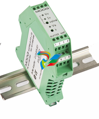 MOOG G123-825-001 BUFFER AMPLIFIER
 -
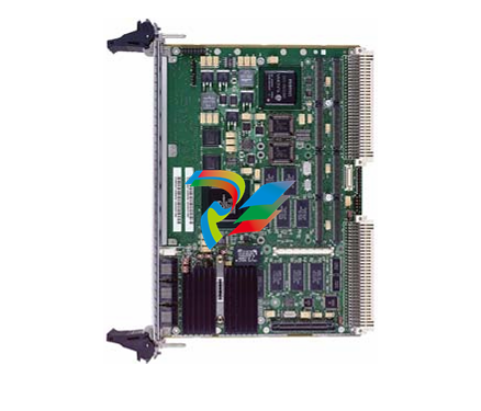 Motorola MVME5100 Series VME Processor Modules
 -
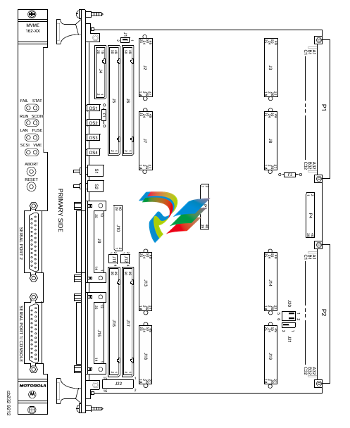 Motorola MVME162 Embedded Controller
 -
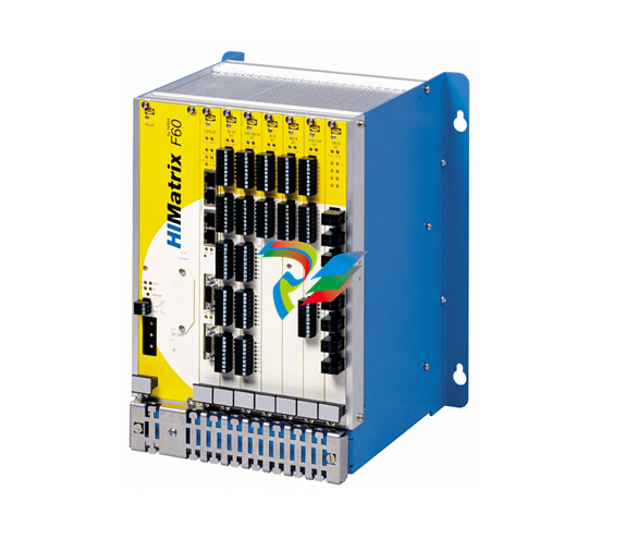 HIMatrix Safety-Related Controller System Manual for the Modular Systems
 -
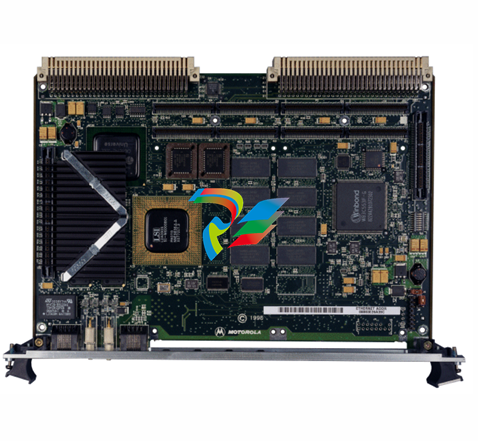 Motorola MVME2400 Series VME Processor Module
 -
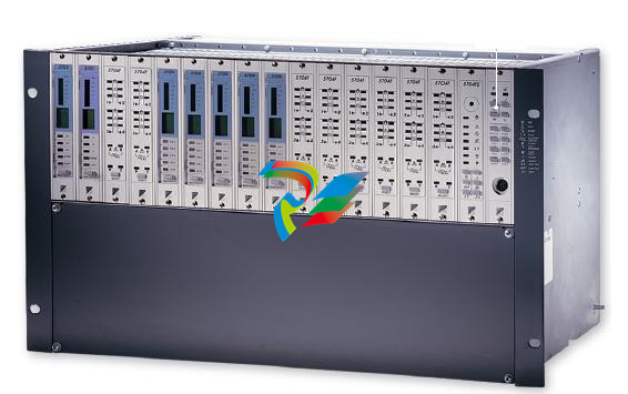 Sieger System 57
 -
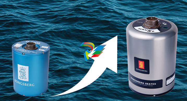 KONGSBERG MRU product line continuation
 -
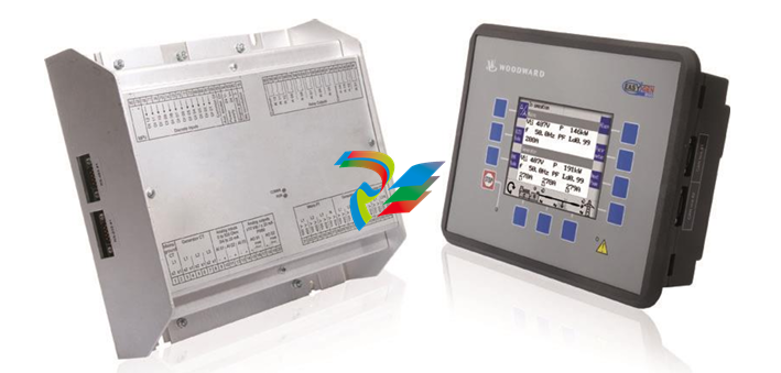 Woodward easYgen-3100/3200 Genset Control for Multiple Unit Operation
 -
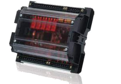 Woodward MFR 300 Multifunction Relay / Measuring
 -
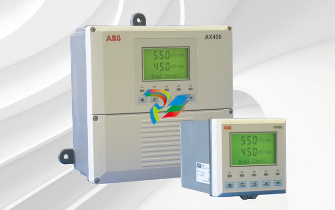 ABB AX410, AX411, AX413, AX416, AX418, AX450, AX455 and AX456 Single and dual input analyzers for low level conductivity
 -
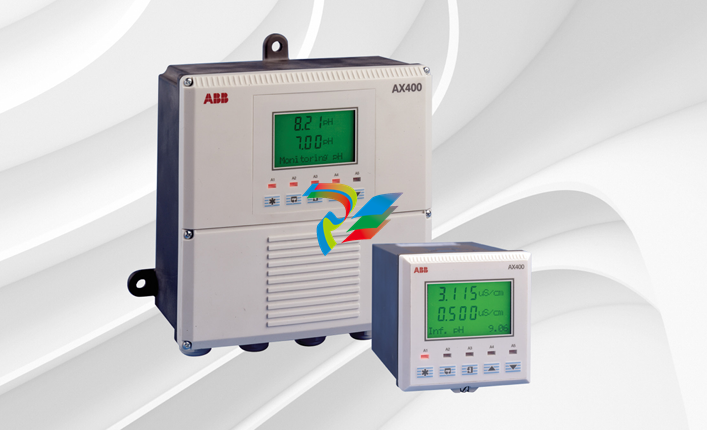 ABB AX410, AX411, AX416, AX450 and AX455 Single and dual input analyzers
 -
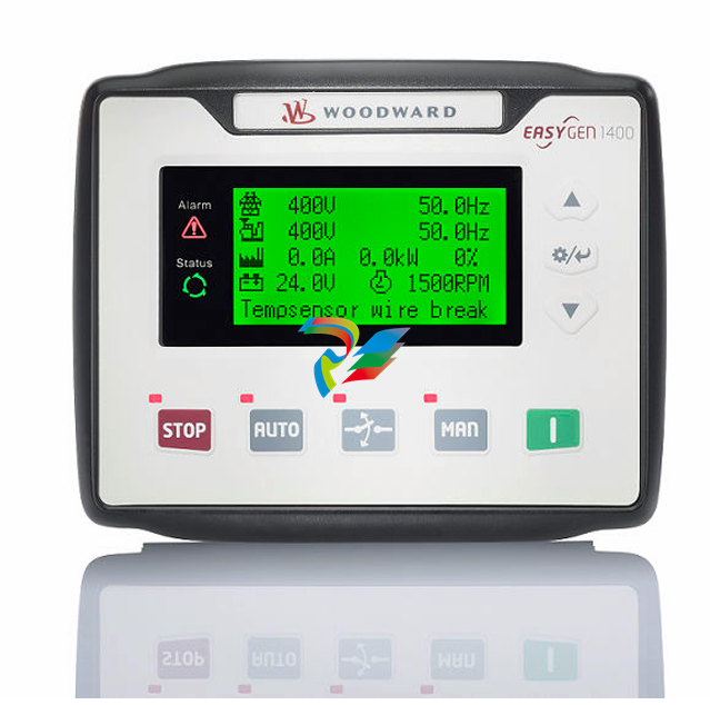 Woodward easYgen-1400 Technical Manual Genset Control
 -
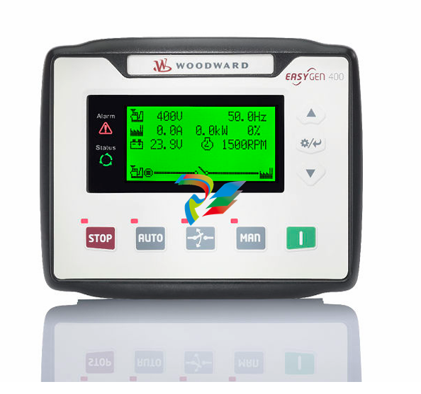 Woodward easYgen-400 Operation Manual Genset Control
 -
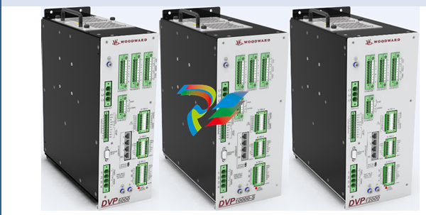 Woodward High Output Digital Valve Positioner (DVP)DVP5000/DVP10000/DVP12000
 -
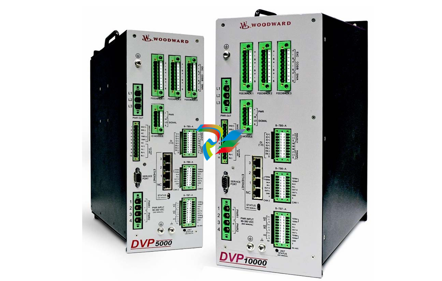 Woodward High Output Digital Valve Positioner DVP5000 and DVP10000
 -
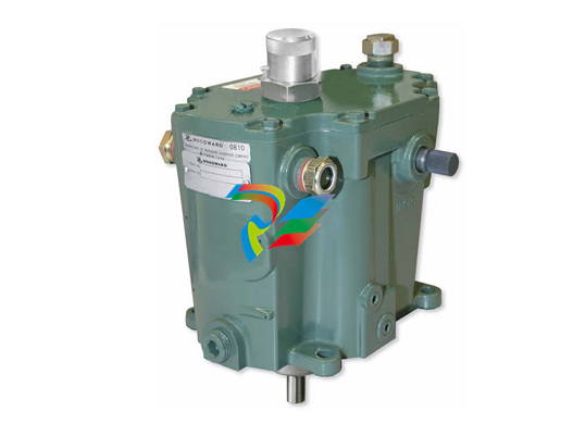 Woodward TG611-13/-17 Overspeed Test Device Conversion Kit
 -
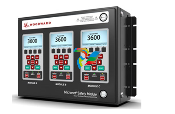 Woodward MicroNet Safety Module (MSM)
 -
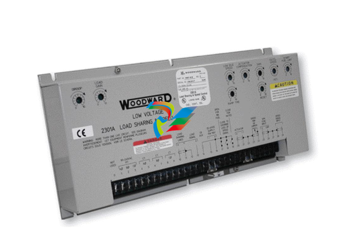 Woodward 2301A Electronic Load Sharing and Speed Control 9905/9907 Series
 -
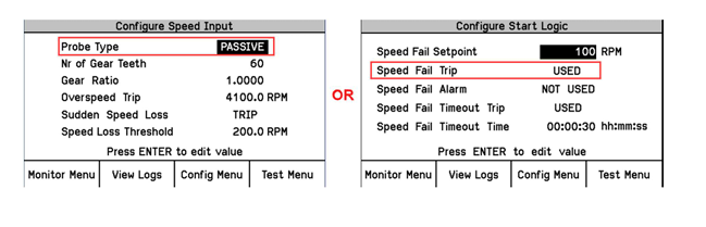 Woodward-Service Bulletin 01671
 -
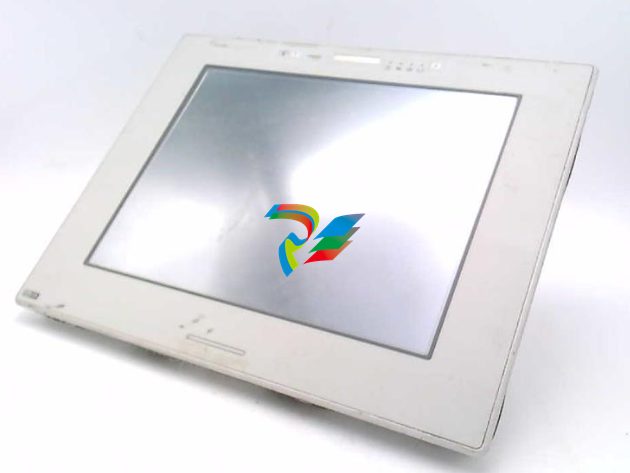 UniOP eTOP40B 12.1” TFT color display
 -
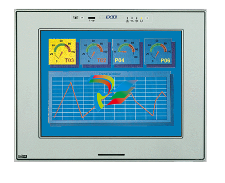 UniOP eTOP40 TFT Color display
 -
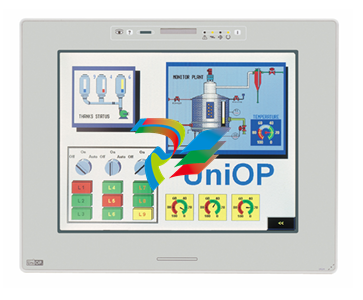 UniOP eTOP33B 10.4” TFT color display
 -
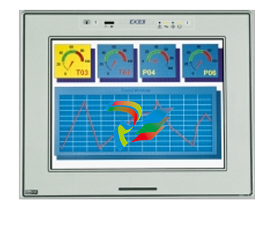 UniOP eTOP33C eTOP33-0050 Resistive touchscreen
 -
UniOP eTOP30. eTOP32 eTOP32-0050 Human-machine interface equipment
-
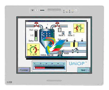 UniOP eTOP20B and eTOP21B eTOP20B-0050
 -
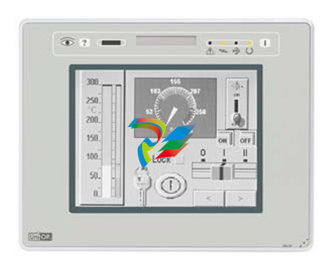 UniOP eTOP12 eTOP12-0050 Advanced human-machine interface equipment
 -
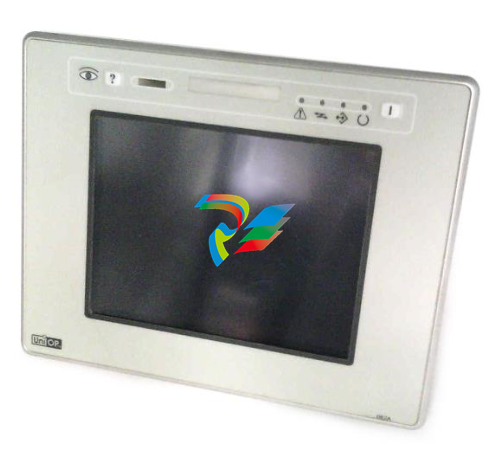 UniOP eTOP11 eTOP11-0050 HMI
 -
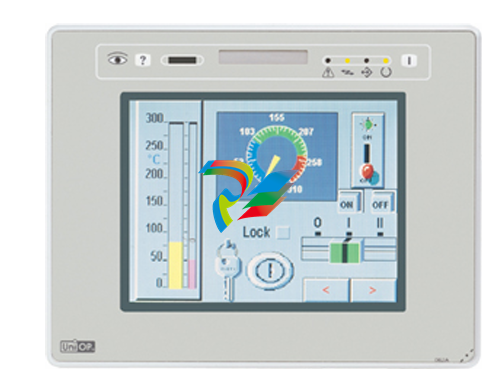 UniOP eTOP06C HMI
 -
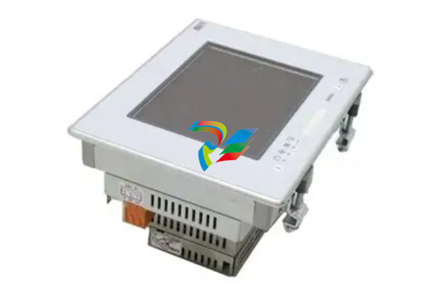 UniOP eTOP06 HMI
 -
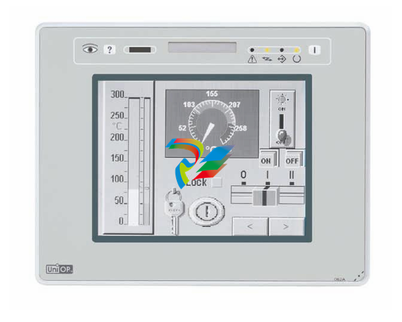 UniOP eTOP05EB eTOP05EB-DF45 HMI
 -
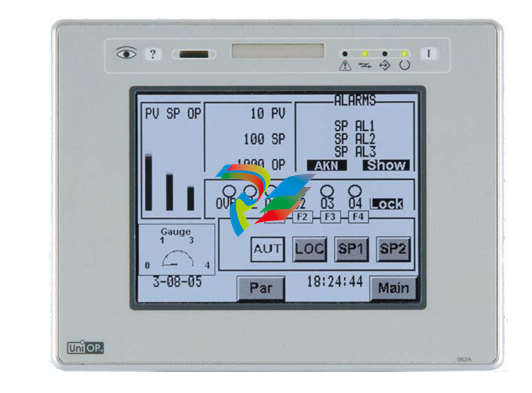 UniOP eTOP05. eTOP05P Human-machine interface equipment
 -
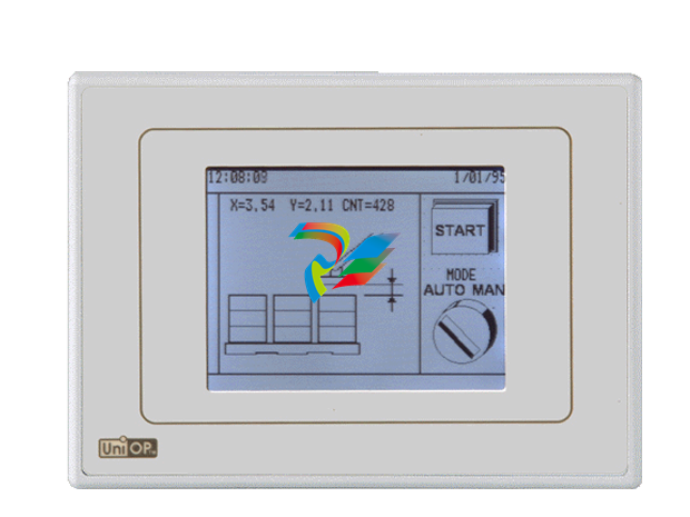 UniOP eTOP03 eTOP03-0046
 -
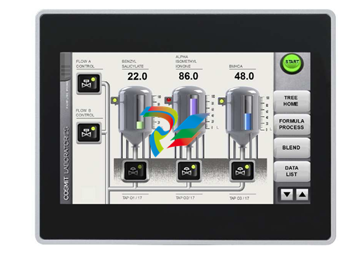 UniOP eTOP507 507U2P1 eTOP Series 500 Human-Machine Interface
 -
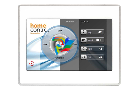 UniOP eTOP307
 -
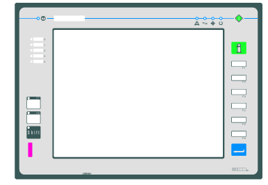 UniOP ETT-VGA Human-machine interface touch unit
 -
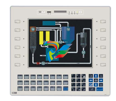 UniOP ePAD32B, ePAD33B and ePAD33BT ePAD33B-0350
 -
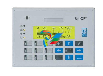 UniOP ePAD05 and ePAD06
 -
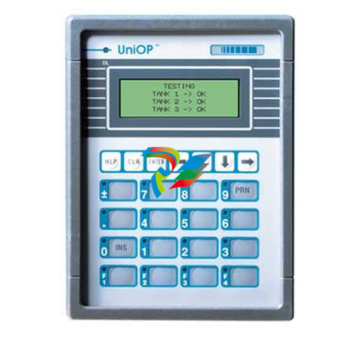 UniOP CP02R-04 Human-machine interface
 -
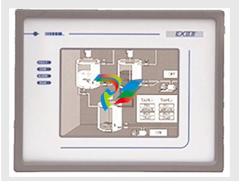 UniOP ERT-16 - Industrial PLC Workstation
 -
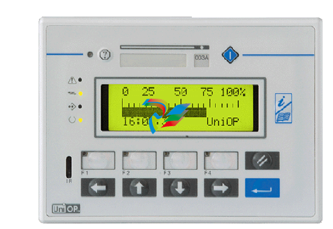 UniOP ePAD03 and ePAD04
 -
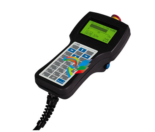 UNIOP EPALM10-DA71 state-of-the-art handheld HMI
 -
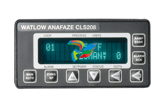 Watlow SERIES CLS200 SPECIFICATION SHEET
 -
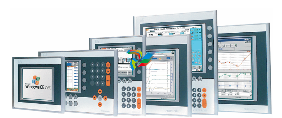 Detailed Explanation of B&R Power Panel 300/400: The Core of Industrial Automation Control
 -
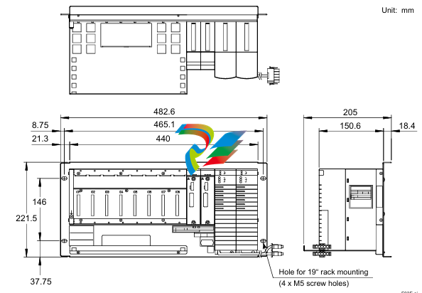 YOKOGAWA Models ANB10S, ANB10D, ANR10S, ANR10D Node Units (for FIO)
 -
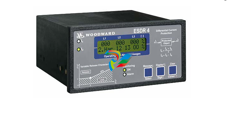 Woodward ESDR 4 Current Differential Protection Relay
 -
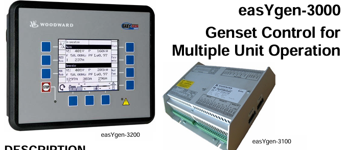 Woodward easYgen-3000 Genset Control for


