
GE Power Conversion P112-6053 Advanced Micro Controller (AMC2)
GE Power Conversion P112-6053 Advanced Micro Controller (AMC2)
1. Product Introduction / Overview
The GE Power Conversion P112-6053 is an industrial-grade high-performance controller from the Advanced Micro Controller 2 (AMC2) platform, originally developed by Converteam (now GE Power Conversion).
Combining a high-speed Intel Pentium-M (1.40 GHz) processor core with 5 integrated Ethernet communication ports and 2 $times$ Serial16+ high-density serial expansion modules, the P112-6053 is engineered for mission-critical industrial applications. It is widely deployed in marine dynamic positioning (DP) systems, complex Distributed Control Systems (DCS), heavy-duty propulsion drives, and multi-channel serial automation infrastructures.
2. Technical Parameter List
| Technical Parameter | Specification Details |
| Manufacturer | GE Power Conversion / Converteam |
| Model / Ordering Code | P112-6053 (AMC2 Series) |
| Processor Core | Intel Pentium-M @ 1.40 GHz (High-Speed Performance Upgrade) |
| System Memory (RAM) | 256 MB DRAM |
| Storage Memory | 256 MB CompactFlash (Solid-State Drive) |
| Operating System | Embedded RTOS / Windows XP Embedded |
| Input Power Voltage | 24 V DC (Operating Range: 19.2 V DC to 28.8 V DC / 13–36 VDC tolerance) |
| Nominal Current Consumption | ~ 1.2 A @ 24 V DC |
| Network Interfaces | 5 $times$ RJ45 Ethernet Communication Ports |
| Onboard Serial Ports | 4 $times$ RS-232 ports |
| Serial Expansion | 2 $times$ Serial16+ high-density serial interface boards |
| USB Interfaces | 2 $times$ USB ports featuring Yamaichi industrial latching |
| Internal Expansion Slots | 4 $times$ PMC / PC104+ hardware extension slots |
| Cooling Method | Passive fanless natural convection |
| Enclosure Dimensions (W $times$ H $times$ D) | 234 mm $times$ 206 mm $times$ 120 mm |
3. Product Features / Core Advantages
High-Performance Pentium-M Processing: Equipped with a 1.40 GHz processor core, offering enhanced computing capacity for heavy multi-loop algorithms and rapid real-time execution.
Dual Serial16+ Expansion Integration: Features dual high-density serial modules, making it ideal for systems interfacing heavily with legacy instruments, multi-channel sensors, and navigational equipment.
5 Integrated Ethernet Ports: Provides extensive network segmentation options, allowing isolated control sub-networks, redundant host links, and high-speed data exchange.
Industrial Fanless Thermal Architecture: Designed for continuous operation up to 70 °C ambient panel temperatures without mechanical cooling fans, eliminating major points of mechanical failure.
Vibration & Shock Resistance: Tested to rigorous industrial standards (15 g mechanical shock rating per IEC 61131-2), ensuring stability on marine vessels and heavy industrial skids.
4. AMC2 Model Classification
The GE AMC2 Series groups processors based on CPU architecture speed (Celeron-M vs. Pentium-M) and modular serial/fieldbus interface configurations:
| Model Code | CPU Architecture | Network & Expansion Configurations | Primary Application Area |
| P110-6052 | 600 MHz Celeron-M | 5 $times$ Ethernet Ports (Base Unit) | Standard Base Industrial Controller |
| P111-6052 | 600 MHz Celeron-M | 5 $times$ Ethernet + 1 $times$ Serial16+ Card | Standard Multi-Serial Field Networks |
| P112-6052 | 600 MHz Celeron-M | 5 $times$ Ethernet + 2 $times$ Serial16+ Cards | High-Density Serial Marine DCS |
| P110-6053 | 1.40 GHz Pentium-M | 5 $times$ Ethernet Ports (High-Speed Base) | High-Performance Process Automation |
| P111-6053 | 1.40 GHz Pentium-M | 5 $times$ Ethernet + 1 $times$ Serial16+ Card | High-Performance Serial Automation |
| P112-6053 | 1.40 GHz Pentium-M | 5 $times$ Ethernet + 2 $times$ Serial16+ Cards | High-Performance DP & Heavy DCS Processing |
| P121-6052 | 600 MHz Celeron-M | 5 $times$ Ethernet + 1 $times$ WorldFIP Card | WorldFIP Network Integration |
| P122-6052 | 600 MHz Celeron-M | 5 $times$ Ethernet + 2 $times$ WorldFIP Cards | Redundant WorldFIP Gateways |
5. Environmental Tolerance Conditions
Operating Ambient Temperature: Rated for passive cooling operations up to 70 °C inside enclosed electrical panels.
Mechanical Shock & Vibration: Built and tested to comply with IEC 61131-2 / IEC 1131-2 specifications, rated up to 15 g shock tolerance.
Relative Humidity: 5% to 95% non-condensing.
Enclosure Protection: Must be housed within an industrial metal cabinet meeting at least an IP54 protection rating.
Electromagnetic Compatibility (EMC): Heavy industrial immunity rating against voltage surges, high-frequency noise, and fast electrical transients.
6. Installation Method
Mechanical Mounting:
Secure the controller enclosure to a clean, flat, grounded metal backplate using the integrated flange-mount brackets.
Maintain a minimum of 50 mm (2 inches) of unobstructed space above and below the housing to facilitate natural thermal convection across the heatsink.
Electrical Power Wiring:
Wire a regulated 24 V DC (tolerated range: 19.2 V to 28.8 V DC) power source to the primary input terminal strip.
Fasten a thick, low-impedance Protective Earth (PE) bonding wire from the chassis ground stud directly to the cabinet ground bus bar to suppress electrical noise on serial communication loops.
Communication Connections:
Attach network control cables into the RJ45 Ethernet ports (LAN1–LAN5) according to system schematic layouts.
Connect multi-channel serial leads to the Serial16+ expansion ports, ensuring cable shields are grounded properly.
7. Operating Instructions
Pre-Power System Check
Verify that the input voltage matches requirements and that the system CompactFlash card and hardware identity key are fully locked into their respective slots.
Startup Sequence
Turn on the 24 V DC power feed. Observe the status LEDs on the front panel:
Power LED: Solid green indicates a stable operating voltage.
Status / Health LEDs: Flashing or steady green sequences denote successful POST execution and runtime software boot.
Maintenance & Replacement Guidelines
Hardware Identity Transfer: When replacing or servicing a controller unit, always transplant the original application CompactFlash memory card and hardware key to the new P112-6053 unit.
Power Isolation: Always disconnect power completely before inserting or removing internal PMC cards, serial modules, or the CompactFlash card to prevent hardware damage.
| User name | Member Level | Quantity | Specification | Purchase Date |
|---|



-
 CTI 2500 Series® Slice Ethernet Remote I/O System
 -
 CTI 2500 Series® Compact Programmable Automation Control System
 -
 CTI 2500 Series® Classic Programmable Automation Control System
 -
 CTI 2500 Series® Bases
 -
 SHINKAWA VM-25 Condition Monitoring System UPDATED
 -
 SHINKAWA VM-5 SERIES OPTIONS
 -
 ABB SACO 64D4 Annunciator unit
 -
 ABB SPAU 140 C Synchro-check relay
 -
 EATON Instructions for the FP-5000
 -
 HONEYWELL TDC 3000X Advanced Process Manager
 -
 HONEYWELL ENHANCED MICRO TDC 3000
 -
 VIBRO-METER VM600Mk2/ VM600 RPS6U rack power supplies
 -
 VIBRO-METER VM600Mk2/ VM600 ABE056 slimline rack
 -
 VIBRO-METER VM600Mk2 RLC16Mk2 relay modules
 -
 VIBRO-METER VM600Mk2 MPC4Mk2 + IOC4Mk2 machinery protection and condition monitoring modules
 -
 VIBRO-METER VM600Mk2 CPUMMk2 + IOCNMk2 rack controller and communications interface module
 -
 VIBRO-METER VM600Mk2 CPUMMk2 + IOCNMk2 rack controller and communications interface module
 -
 ADLINK PCI/PCIe-7300A, cPCI-7300 32-CH 80 MB/s High-Speed Digital I/O Cards
 -
 ADLINK cPCI-7248/7249R 48-CH DIO & Timer/Counter Cards
 -
 ADLINK PCI-7230/7233/7234. LPCI/LPCIe/cPCI-7230 32-CH Isolated DIO Cards
 -
 ADLINK cPCI-6965 Series Value 6U CompactPCI® Intel® Core™2 Duo
 -
 ADLINK cPCI-6910 Series 6U CompactPCI® Dual-Core Intel® Xeon® Processor LV / ULV Universal Blade
 -
 ADLINK CPCI-6670 6U CompactPCI Low Power Pentium® III SBC
 -
 ADLINK cPCI-6625/6 Series 6U CompactPCI® PlusIO blade with Intel® Core™ i7/i3 Processor
 -
 ADLINK 3U CompactPCI CPU Modules
 -
 ADLINK CM-435 Extreme Rugged™ PC/104 Single Board Computer
 -
 ADLINK PCI-8254/8258 DSP-based 4/8-axis Advanced Motion Controllers
 -
 ADLINK NuPRO-E43 PICMG® 1.3 Full-Size LGA1151 with 6th/7th Generation Intel® Core™ i7/i5/i3
 -
 ADLINK DLAP-211-JNX/DLAP-211-JT2/ DLAP-211-Nano
 -
 Hirschmann RS30-1602O6O6SDAE compact OpenRail managed Ethernet switches
 -
Hirschmann RS30-0802O6O6SDAE Ethernet switch
-
 Hirschmann RS20-1600T1T1SDAE Management-type Ethernet switch
 -
 Hirschmann OCTOPUS 24M Limited Availability/Passive
 -
 Hirschmann MSP30-24040SCZ9MRHHE3A
 -
 Hirschmann MAR1040-4C4C4C4C9999SMMHRHHXX.X. Gigabit Ethernet Switch configurator
 -
 Hirschmann Industrial Ethernet Rail Switch SPIDER II, SPIDER II Giga, SPIDER II PoE
 -
 Hirschmann Industrial Ethernet Firewall EAGLE One
 -
 Hirschmann Industrial Security Router EAGLE20/30
 -
 Hirschmann Description and operating instructions RS2-xTX/xFX EEC
 -
 Basler Electric DECS-200 Digital Excitation Control System
 -
 Basler Electric GENERATOR PROTECTION SYSTEM BE1-GPS100
 -
 Jaquet FT3000 Speed measurement system
 -
 Hirschmann Industrial Ethernet Ruggedized Switch MACH1000 Family
 -
 Basler Electric BESTCOMSPlus®
 -
 ETEL AccurET MODULAR 300 EA-P2M-300-xxxxxA controller
 -
 Basler Electric ES Series Protection Relays
 -
 ABB Multifunction Protection and Switchbay Control Unit REF542plus
 -
 EMERSON AMS 2140 Machinery Health Analyzer
 -
 Hirschmann Industrial Ethernet Rail Switch RS20 Basic Family
 -
 GE Grid Solutions P40U Px40 USB Adaptor
 -
 ABB ontinuous Gas Analyzers AO2000 Series AO2040CU Ex Central Unit in Category 2G
 -
 ABB Advance Optima AO2000 Series Continuous gas analyzers Models AO2020. AO2040
 -
 Advance Optima Module Uras 14
 -
 SAACKE control optimization
 -
 SAACKE se@vis efficiency monitor
 -
 SAACKE se@vis pro
 -
 SAACKE se@vis eco
 -
 SAACKE se@vis compact
 -
 HIRSCHMANN Industrial ETHERNET Switch MICE MS20/MS30
 -
 HIRSCHMANN MICE Media modules
 -
 Kongsberg GL-10 Level Switch
 -
 B&R ACOPOSinverter P74 frequency converter
 -
 Beckhoff CX2020 | Basic CPU module (service phase)
 -
 Beckhoff CX1010 | Basic CPU module (service phase)
 -
 Beckhoff CX5120 | Embedded PC with Intel Atom® E3815
 -
 Beckhoff CP69xx-xxxx-0010 | Economy built-in Control Panel with DVI/USB Extended interface
 -
 Beckhoff CP29xx-0000 | Multi-touch built-in Control Panel with DVI/USB Extended interface
 -
 SAACKE Monoblock Rotary Cup Burner SKVJ-M
 -
 ABB Plantguard Fault Tolerant Technology Architecture and Software
 -
 OMRON H8PR-8/H8PR-8P H8PR-16/H8PR-16P H8PR-24/H8PR-24P Rotary Positioner
 -
 ABB PFSA107-Z42 DTU Stressometer Digital Transmission Unit
 -
 Nidec Mentor MP
 -
 IBA ibaNet-E
 -
 IBA FO Connection to Reflective Memory
 -
 IBA FO Connection to Siemens Systems
 -
 IBA Interface Cards For Fiber Optic Connections
 -
 IBA Field and Drive Buses
 -
 IBA ibaPADU-S Modular System
 -
 IBA ibaMAQS
 -
 STUCKE SYMAP®ARC
 -
 STUCKE SYMAP®R
 -
 STUCKE SYMAP®Compact
 -
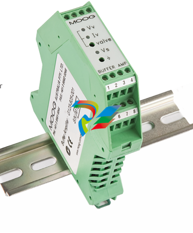 MOOG G123-825-001 BUFFER AMPLIFIER
 -
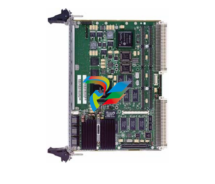 Motorola MVME5100 Series VME Processor Modules
 -
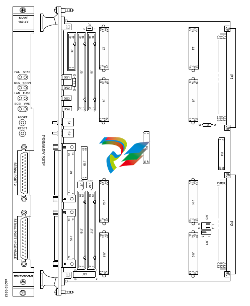 Motorola MVME162 Embedded Controller
 -
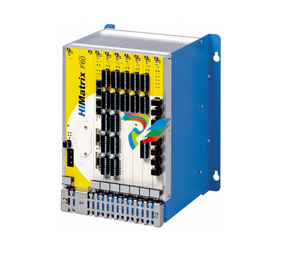 HIMatrix Safety-Related Controller System Manual for the Modular Systems
 -
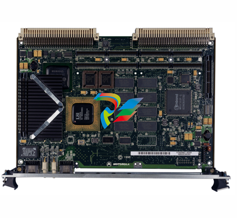 Motorola MVME2400 Series VME Processor Module
 -
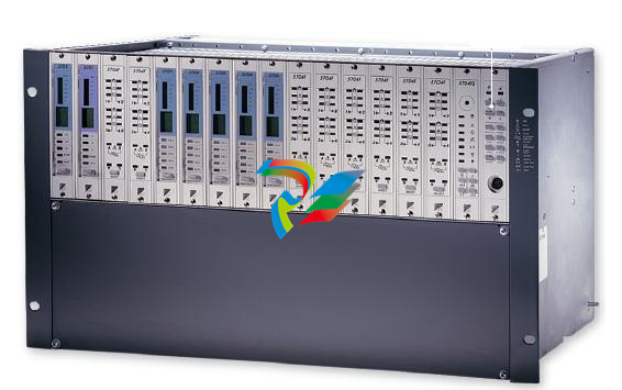 Sieger System 57
 -
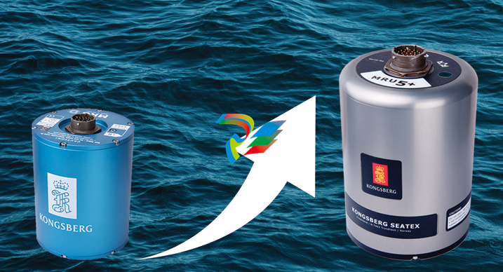 KONGSBERG MRU product line continuation
 -
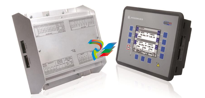 Woodward easYgen-3100/3200 Genset Control for Multiple Unit Operation
 -
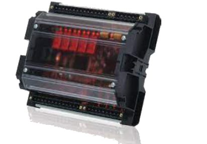 Woodward MFR 300 Multifunction Relay / Measuring
 -
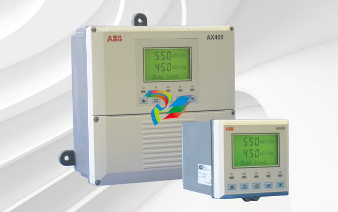 ABB AX410, AX411, AX413, AX416, AX418, AX450, AX455 and AX456 Single and dual input analyzers for low level conductivity
 -
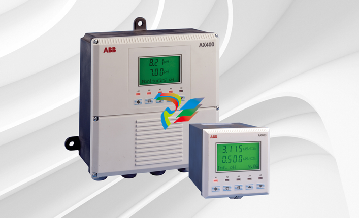 ABB AX410, AX411, AX416, AX450 and AX455 Single and dual input analyzers
 -
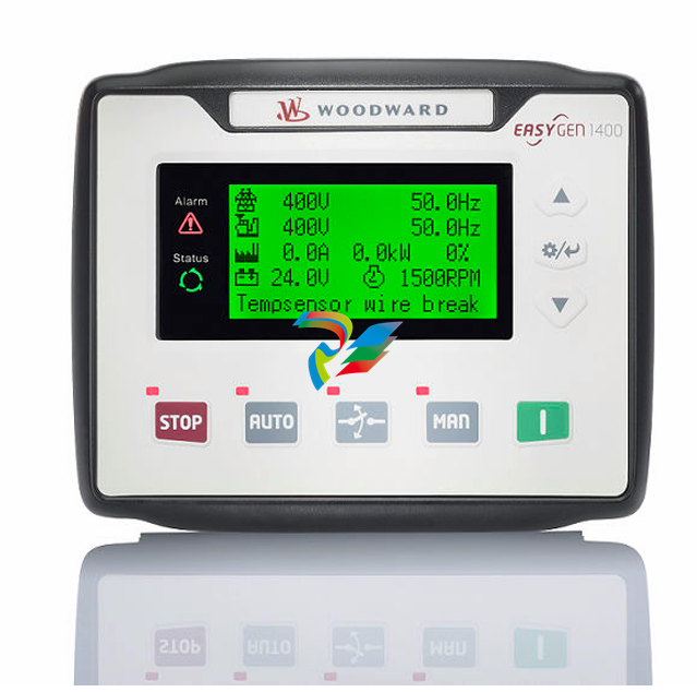 Woodward easYgen-1400 Technical Manual Genset Control
 -
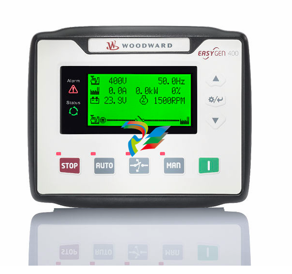 Woodward easYgen-400 Operation Manual Genset Control
 -
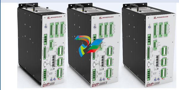 Woodward High Output Digital Valve Positioner (DVP)DVP5000/DVP10000/DVP12000
 -
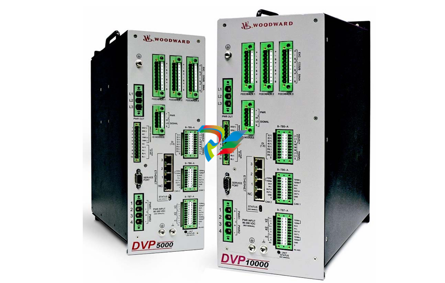 Woodward High Output Digital Valve Positioner DVP5000 and DVP10000
 -
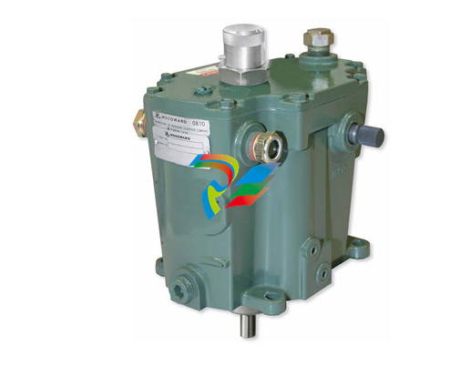 Woodward TG611-13/-17 Overspeed Test Device Conversion Kit
 -
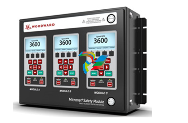 Woodward MicroNet Safety Module (MSM)
 -
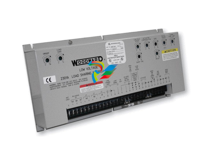 Woodward 2301A Electronic Load Sharing and Speed Control 9905/9907 Series
 -
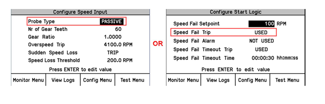 Woodward-Service Bulletin 01671
 -
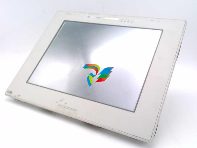 UniOP eTOP40B 12.1” TFT color display
 -
 UniOP eTOP40 TFT Color display
 -
 UniOP eTOP33B 10.4” TFT color display
 -
 UniOP eTOP33C eTOP33-0050 Resistive touchscreen
 -
UniOP eTOP30. eTOP32 eTOP32-0050 Human-machine interface equipment
-
 UniOP eTOP20B and eTOP21B eTOP20B-0050
 -
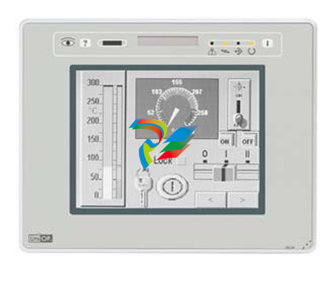 UniOP eTOP12 eTOP12-0050 Advanced human-machine interface equipment
 -
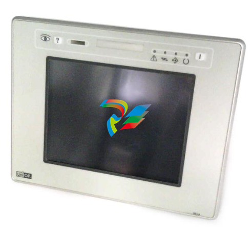 UniOP eTOP11 eTOP11-0050 HMI
 -
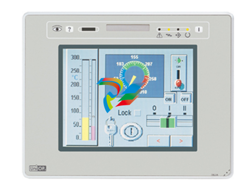 UniOP eTOP06C HMI
 -
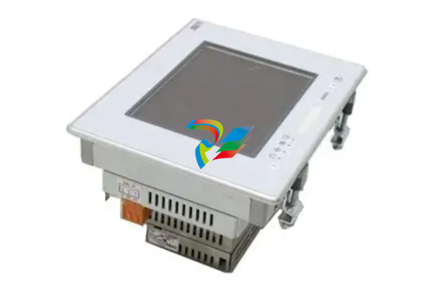 UniOP eTOP06 HMI
 -
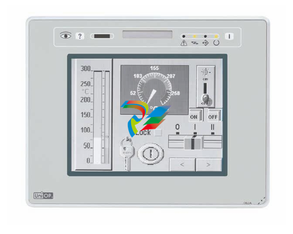 UniOP eTOP05EB eTOP05EB-DF45 HMI
 -
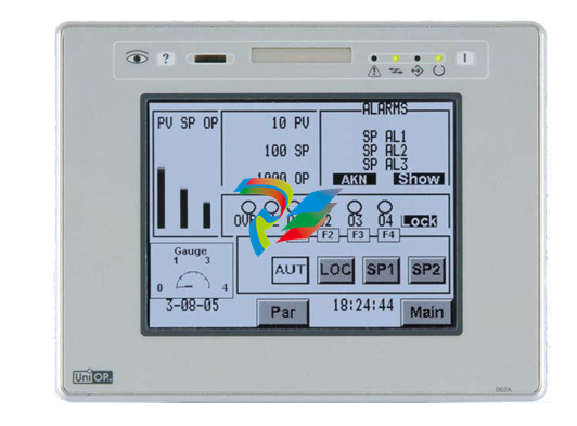 UniOP eTOP05. eTOP05P Human-machine interface equipment
 -
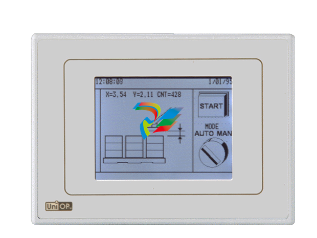 UniOP eTOP03 eTOP03-0046
 -
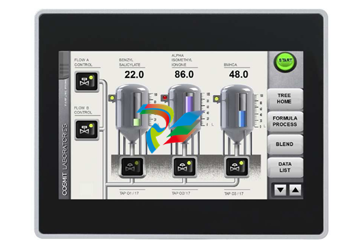 UniOP eTOP507 507U2P1 eTOP Series 500 Human-Machine Interface
 -
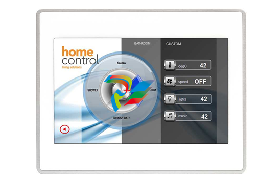 UniOP eTOP307
 -
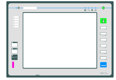 UniOP ETT-VGA Human-machine interface touch unit
 -
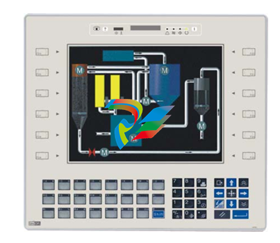 UniOP ePAD32B, ePAD33B and ePAD33BT ePAD33B-0350
 -
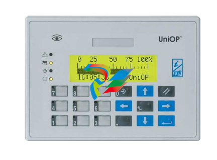 UniOP ePAD05 and ePAD06
 -
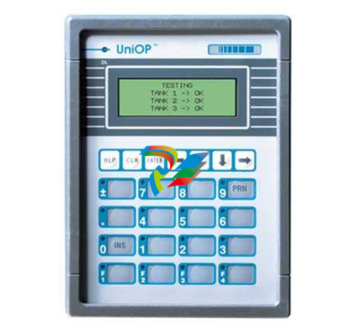 UniOP CP02R-04 Human-machine interface
 -
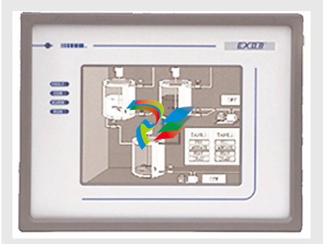 UniOP ERT-16 - Industrial PLC Workstation
 -
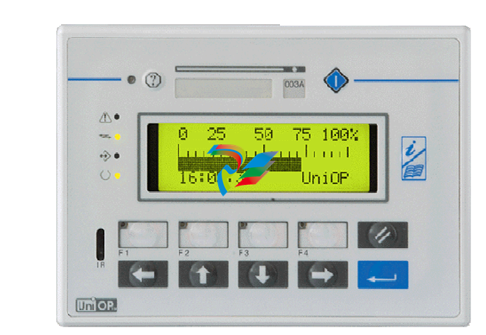 UniOP ePAD03 and ePAD04
 -
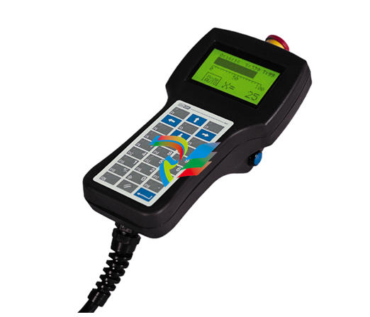 UNIOP EPALM10-DA71 state-of-the-art handheld HMI
 -
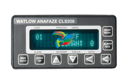 Watlow SERIES CLS200 SPECIFICATION SHEET
 -
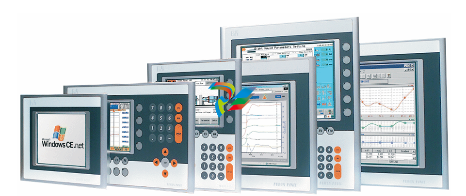 Detailed Explanation of B&R Power Panel 300/400: The Core of Industrial Automation Control
 -
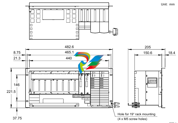 YOKOGAWA Models ANB10S, ANB10D, ANR10S, ANR10D Node Units (for FIO)
 -
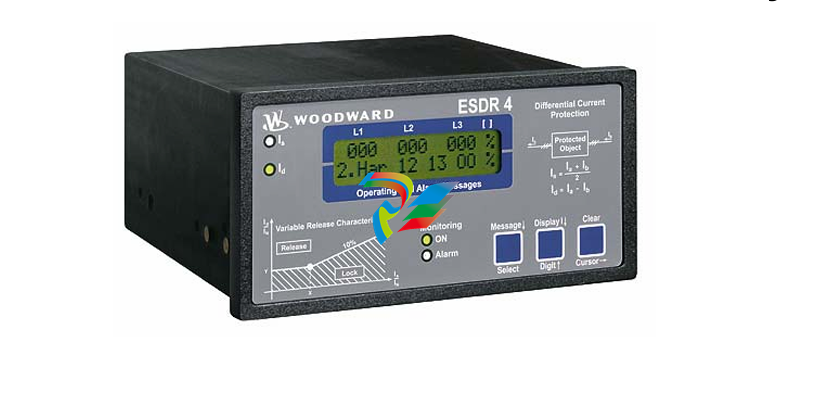 Woodward ESDR 4 Current Differential Protection Relay
 -
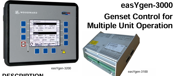 Woodward easYgen-3000 Genset Control for


