Less leakage results in reduced product loss, increased efficiency, and improved energy management.
Figure 1: This control valve is subjected to EPA’s Method 21 “sniff ” test to determine the fugitive emission leak rate after a prescribed number of mechanical and thermal cycles. There are many methods of sealing valve stems on control and isolation valves. When chosen carefully, a valve stem seal provides years of reliable service, reduces environmental emissions, and minimizes product loss. When inappropriately applied, a valve stem seal can leak constantly, increase maintenance costs, create environmental issues, and place operating personnel at risk. The right valve stem seal increases efficiency by minimizing product loss, which in turn reduces energy use, because less product needs to be made to satisfy demand.
Valve stem seals explained
Before delving into the details of selecting a valve sealing method, it is best to understand the challenges of sealing a valve stem and explain how this might be done. Control and block valves fall into one of two major categories: sliding stem or rotary.
A sliding stem valve has a rod protruding from the body that rises and falls to open and close the valve. A rotary valve has a shaft extending out the side of the valve that is connected to a plug, disc, or ball. As the shaft turns, the rotary valve opens and closes. In either design, the valve stem must exit the body and be capable of relatively friction-free movement, while containing the process and preventing leaks.
The valve stem sealing assembly makes that possible. Sealing is usually accomplished in one of two ways: conventional packing or bellows seals. Details of how these methods work, along with pros and cons of each method, follows.
Measuring valve stem seal performance
Valve stem seals must accomplish two contradictory goals. First, they must seal the valve stem completely and reduce—and ideally eliminate—any fugitive emissions from the process. Second, they must accomplish this feat while allowing the valve stem to move freely and continue sealing, even as the valve stem cycles thousands of times. Several industrial standards address these requirements, but the required performance and test methods vary significantly.
The three main fugitive emissions standards are TA Luft, FCI 91-1, and ISO 15848. TA Luft is the least comprehensive of the three, offering leak rate standards based on gasket size and process temperature. However, it lacks specific test parameters for the number of test cycles required or the travel distance, so it is hard to compare the leakage results among different valve designs.
FCI 91-1 was created by the Fluid Control Institute and is more closely aligned with the leak detection and repair requirements mandated by the Environmental Protection Agency (EPA). It uses EPA’s Method 21 to “sniff” the valve packing and determine the leak rate (Figure 1). This standard provides details on how to test a valve. A valve stem seal design achieves various classification ratings based on the resulting leak rate after a specified number of mechanical and thermal cycles.
By far, the most comprehensive standard is ISO 15848. It has a variety of leakage classification rates for both control and isolation valves based on mechanical cycles, thermal cycles, and stem size. It also allows testing with either helium or methane, and it dictates two different ways to measure stem seal leakage for helium, each of which is much more involved than a simple sniff test. Specifically, the upperworks of the valve are encased in an airtight enclosure and either flushed with a test gas or subjected to a full vacuum, while the inside of the valve is pressurized with helium. The amount of leakage can then be precisely measured.
When evaluating the performance of a valve stem seal arrangement, it is important to determine how the valve was tested and what specific classification it met. It is relatively easy to achieve very low leakage rates if the valve is mechanically cycled a small number of times. It is much more difficult to achieve and maintain very low leakage rates when the valve is mechanically cycled thousands of times, while enduring thermal cycles as well. The thermal cycles affect sealing due to the high expansion rate of PTFE (a synthetic fluoropolymer of tetrafluoroethylene, also known as Teflon) and the poor recovery rate of graphite, making packing design challenging.
Sealing valve stems with packing
The most common method of valve stem sealing employs a series of PTFE or graphite rings that encircle the valve shaft (Figure 2). The rings are compressed with a combination of a packing follower, packing flange, and bolts to push down and squeeze the packing rings against the shaft. The compressed rings allow the valve stem to move while maintaining a seal against the valve body and shaft to keep process fluids from passing through the stem and escaping. In certain applications, the packing need only protect against gross process leaks, so relatively minor fugitive emissions are not a concern and free stem movement is considered a more important requirement.
To achieve and maintain low emissions, packing must be “live loaded” to keep constant pressure on the sealing rings (Figure 2). This is usually accomplished using compressed Belleville-type springs. These springs maintain a constant force on the packing, ensuring it seals over time, even as the rings wear from stem movement. Unfortunately, the increased pressure tends to restrict valve movement, so the sealing materials and valve stem finish must be carefully chosen to minimize fugitive emissions, while allowing valve stem movement.
Figure 2: The picture on the left shows a typical rising stem control valve with standard packing. More modern packing designs, shown on the right, employ compressed Belleville-type or other special springs to maintain constant pressure on the packing rings. This ensures the fugitive emissions are limited to 100 ppm or less, even as the rings wear.
Sealing valve stems with bellows
An alternative to valve packing is a valve bellows seal. A bellows seal uses a welded or mechanically formed metal barrier around the valve stem that can compress and stretch like an accordion (Figure 3). Because the seal is made of metal with a very low rate of deformation in critical areas, bellows seals achieve virtually zero leakage.
Figure 3: Bellows seal designs usually employ a welded leaf design (detail left and middle) or a mechanically formed design (right). A formed design can withstand many more cycles than a welded leaf design, but it is usually about three times longer.Welded leaf bellow seals (Figure 3) are manufactured by welding together a stack of washer-like plates of thin metal to make a flexible seal with many folds over a given length. A formed bellows (Figure 3) uses a flat sheet of metal formed and welded into a tube. The tube is then mechanically and hydraulically formed into a bellows.
Both designs can stretch about the same distance per fold, but because the formed bellows has far fewer folds per inch, its overall length is usually three times longer (Figure 4). However, the reduced number of welds and corresponding mechanical stress allow formed bellows to last significantly longer in most applications.
Because bellow seals are constructed of relatively thin metal and subjected to mechanical stress and corrosion, they can crack and fail over time. For this reason, a bellows seal valve usually has a standard packing above it to contain the process should the bellows fail in operation.
Figure 4: This valve employs formed bellows to achieve zero valve stem leakage. As an added precaution, the valve also includes integral standard packing above the bellows.
Packing versus bellows
Each method of valve stem sealing has pros and cons, so the best choice depends on the application. Perhaps the biggest advantage of standard or environmental packing is its comparatively low cost, along with a wide variety of valve packing materials and designs to suit most applications. Valve packings can also be adjusted and replaced without disassembling the valve.
The biggest advantage of a bellows design is its ability to deliver zero leakage. Such a specification is critical for lethal service applications. The bellow materials can also be chosen to handle higher temperatures and corrosive applications. Because the operational life of a bellows seal is based on the number and length of strokes, the estimated time to failure can be predicted with some accuracy, so replacement can be planned.
Each design has disadvantages as well. The performance and lifetime of packing is based on many variables, which are not always easily predicted. Small leaks usually can be addressed by tightening the packing, but at some point, the packing must be replaced. Also, the surface finish of the valve stem can have a big impact on the life and performance of a packing design. Regardless, all valve packing will leak to some extent, and this may not be acceptable in certain applications.
As mentioned previously, bellows seals will fatigue and eventually fail. When that occurs, the valve must be fully disassembled to replace the bellows seal. For this reason, the total cost of ownership for a bellows seal is typically higher than that of packing.
Application examples
When properly selected and applied, both packing and bellows seals can handle challenging applications. In one liquified natural gas application in Australia, a 24-inch by 30-inch letdown valve used a specially designed environmental packing arrangement and had very low valve stem leakage, despite operating at cryogenic temperatures around –300°F (Figure 5). Any fugitive emission from this valve translated into lost product, lost energy, and environmental damage—so it was critical to minimize leaks.
Figure 5: This 24-inch by 30-inch letdown valve employs a specially designed large stem diameter environmental seal for extremely low leakage rates, as demonstrated here during a test at –56°F. A Chinese chemical plant had a lethal service hydrogen cyanide application requiring virtually zero leakage while in operation, so a bellows seal design was selected. Upon commissioning, the plant reported zero measurable emissions, and after six years, still had no reported leakages. The valves went through 50,000 full cycles and more than 10,000 partial cycles annually.
Final thoughts
Proper selection of valve stem sealing is a critical component of the valve specification process. When chosen wisely, the design will perform reliably for the long term, translating into significant reductions in environmental emissions, product losses, and maintenance costs. Losing less product improves efficiency and is a key component of energy management.
The number of design options are extensive, so end users may find it helpful to consult with their valve vendor to determine the best sealing design, materials of construction, and other details for their specific applications.


 IS200EPMCH1GE Mark VIe Patch Cord Power Distribution Card
 VMICPCI-7632-03310 IS215UCCAH3A 350-657362-003310J GE gas turbine system control processor board
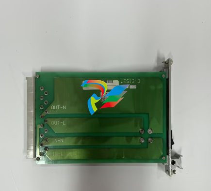 WEA13-13 2508-21001 Control Module / I/O Board
.jpg) WES5120 2340-21004 Controller Main Module
WES5120 2340-21004 Controller Main Module WES5120 2340-21006 Field Controller Master Unit Module
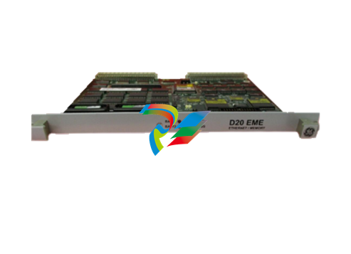 WESDAC D20ME 18-MAR-13 Excitation Control Module
 D20 EME 2400-21004 Ethernet communication and expansion module
 GE DS3800XTFP1E1C Thyristor Fan Out Board Brand
 GE SR745-W2-P1-G1-HI-A-L-R-E Feeder protection relay
 GE IS230TNDSH2A Discrete Output Relay Module Brand
 GE Fanuc IS200TDBSH2ACC Mark VI Terminal Board Brand
 GE PMC-0247RC-282000 350-93750247-282000F Disk Drive
 GE VMIVME-1150 Serial Communications Controller
 GE VMIVME-5576 Fiber-Optic Reflective Memory with Interrupts
 GE VMIC Isolated Digital Output VMIVME-2170A
 GE MULTILIN 760 FEEDER MANAGEMENT RELAY 760-P5-G5-S5-HI-A20-R-E
 GE IS200AEPAH1BKE IS215WEPAH2BB Printed circuit board
 GE IS210BPPCH1A Mark VIe I/O Pack Processor Card
 GE IS220PRTDH1A 336A4940CSP6 High-Performance RTD Input Module
 GE IS420ESWBH3A IONET Switch Module
 GE 516TX 336A4940DNP516TX 16-port Ethernet switch
 GE EVMECNTM13 Embedded control module
 GE Hydran M2-X Enhanced Monitoring with Extended Sensor Life
 GE UR6CH Digital I/O Module
 GE IC695CPU315-CD Central processing unit
 GE 531X305NTBAMG1 DR Terminal Board
 GE 531X305NTBALG1 NTB/3TB Terminal Board 531X Series
 GE 531X305NTBAJG1 NTB/3TB Terminal Board.
 GE 531X305NTBAHG1 NTB/3TB Terminal Board 531X
 GE 531X305NTBAEG1 is a PCB that functions as a DR terminal board.
 GE Digital Energy D20 Analog Input Module
 GE 94-164136-001 main board Control board
 GE 269 PLUS-D/O-100P-125V Digital motor relay
 GALIL DMC-9940 High-performance motion controller
 FUJI NP1BS-08 base plate
 FUJI NP1Y32T09P1 Transistor drain type digital output module
 FUJI NP1Y16R-08 Digital Output Module
 FUJI NP1X3206-A High-speed digital input module
 FUJI NP1AYH4I-MR current output module
 FUJI NP1S-22 Power module redundancy
 FUJI RPXD2150-1T servo drive module
 FUJI FVR008E7S-2UX Ac frequency converter
 FUJI Ac frequency converter FVR008E7S-2
 FUJI FVR004G5B-2 Small general-purpose frequency converter
 FUJI A50L-2001-0232 Industrial control module
 FUJI A50L-001-0266#N High-performance servo amplifier
 Honeywell FS7-2173-2RP Gas sensor
 Honeywell 10106/2/1 Digital Input Module in Stock
 FRCE SYS68K CPU-40 B/16 PLC core processor module
 Foxboro FBM I/O cards PBCO-D8-009
 Foxboro AD916AE Digital Control System (DCS) Module
 GE SR750-P5-G5-S5-HI-A20-R-E Multilin Relay
.jpg) FOXBORO H90 H90C9AA0117S Industrial Computer Workstation
FOXBORO H90 H90C9AA0117S Industrial Computer Workstation.jpg) Foxboro N-2AX+DIO Multi-functional input/output module
Foxboro N-2AX+DIO Multi-functional input/output module Foxboro RH924WA FCP280 Fiber Optic Network Adapter
 FOXBORO H92 Versatile Hardware Component In
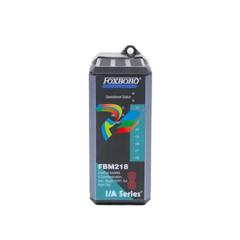 Foxboro FBM218 P0922VW HART® Communication Redundant Output Interface Module
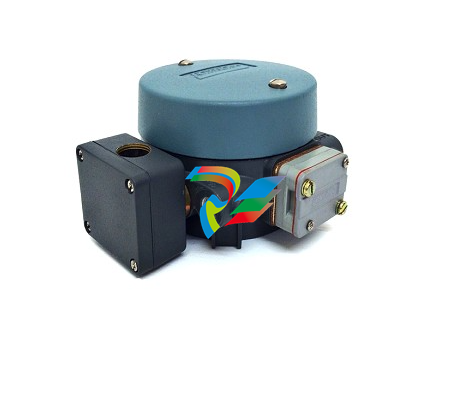 Foxboro E69F-TI2-J-R-S E69F Series Current-To-Pneumatic Signal Converter
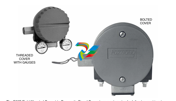 Foxboro E69F-BI2-S Converter
.jpg) Foxboro H92A049E0700 The host of the DCS control station
Foxboro H92A049E0700 The host of the DCS control station Foxboro H90C9AA0117S Industrial computer workstation
 Foxboro RH101AA High-performance industrial control module
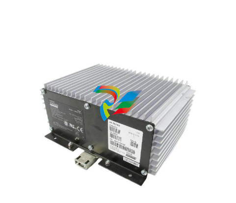 Foxboro P0922YU FPS400-24 I/A Series Power supply
.png) FOXBORO P0973LN Chassis-based managed switch with independent power supply
FOXBORO P0973LN Chassis-based managed switch with independent power supply.jpg) FOXBORO P0926PA Input/output module
FOXBORO P0926PA Input/output module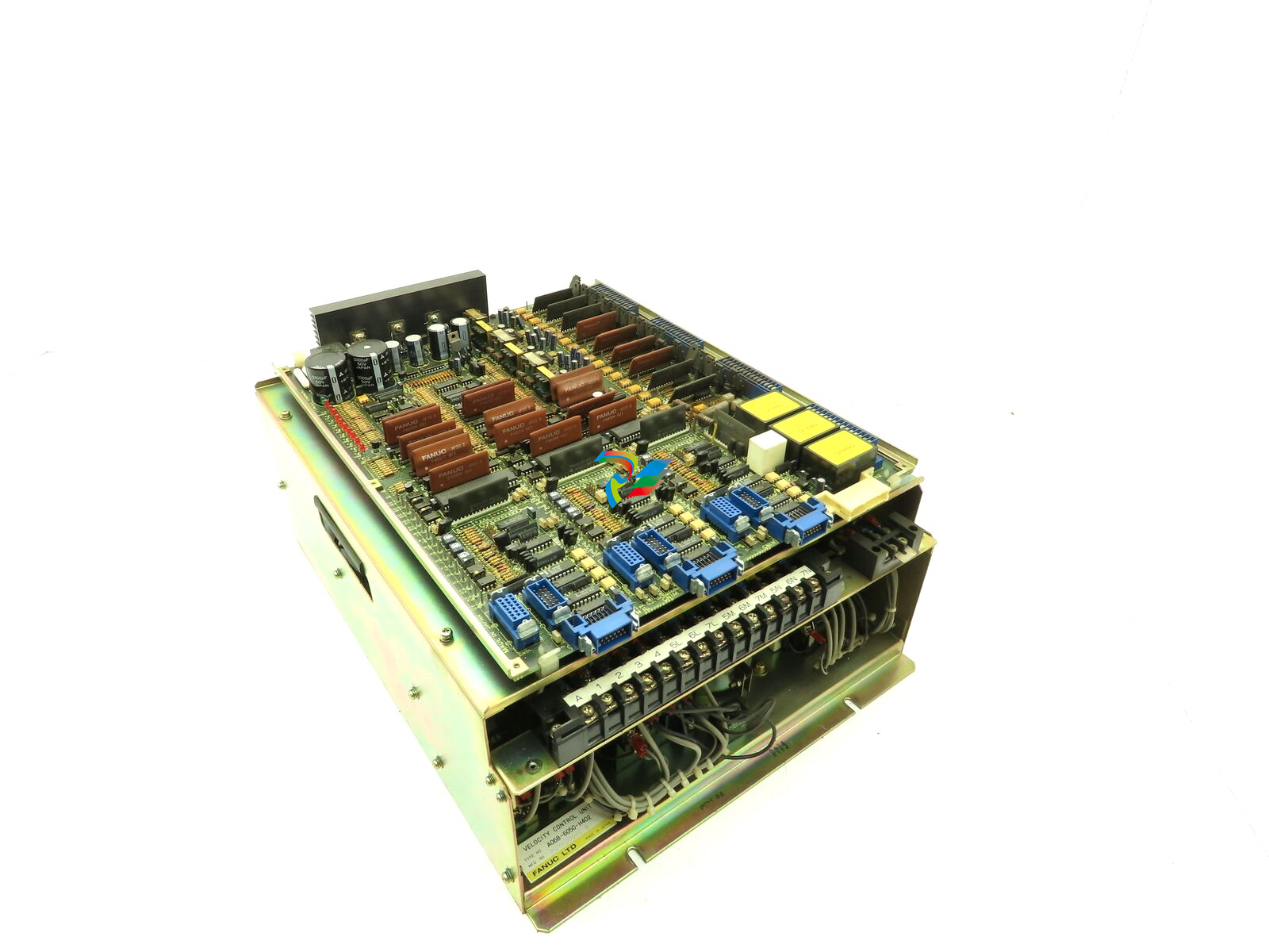 Fanuc A06B-6050-H402 3 AXIS ANALOG AC SERVO DRIVE
.jpg) FOXBORO L0130AD L0130AE-0H Power module group
FOXBORO L0130AD L0130AE-0H Power module group_lVjBYb.jpg) FOXBORO 0399085B 0303440C+0303458A Combination Control Module
FOXBORO 0399085B 0303440C+0303458A Combination Control Module FOXBORO SY-0399095E (SY-0303451D+SY-0303460E) Process control board
.jpg) FOXBORO 0399071D 0303440C+0303443B Input/Output (I/O) Module
FOXBORO 0399071D 0303440C+0303443B Input/Output (I/O) Module.jpg) FOXBORO RH924UQ Redundant Controller module
FOXBORO RH924UQ Redundant Controller module FFOXBORO E69F-TI2-S current pneumatic converter
 FOXBORO FBM219 RH916RH Discrete I/O Module
 FOXBORO FBM227 P0927AC Module
.jpg) FOXBORO 0399144 SY-0301059F SY-1025115C/SY-1025120E I/O module
FOXBORO 0399144 SY-0301059F SY-1025115C/SY-1025120E I/O module.jpg) FOXBORO SY-60399001R SY-60301001RB Industrial Control Module
FOXBORO SY-60399001R SY-60301001RB Industrial Control Module FOXBORO 0399143 SY-0301060R SY-1025115C SY-1025120E Combined control board
 FOXBORO 873EC-JIPFGZ electrodeless conductivity analyzer
 FOXBORO P0916PH (High-density HART I/O Module)
 FOXBORO 870ITEC-AYFNZ-7 Intelligent Electrochemical Transmitters
 FOXBORO Compact FBM240. Redundant with Readback, Discrete
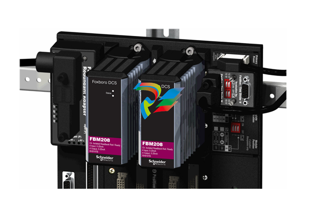 FOXBORO FBM208/b, Redundant with Readback, 0 to 20 mA I/O Module
 FOXBORO FBM201e Analog Input (0 to 20 mA) Interface Modules
.jpg) FOXBORO P0916WG Terminal cable
FOXBORO P0916WG Terminal cable FOXBORO P0926MX 2-Port Splitter
.jpg) FOXBORO AD908JQ High-Frequency Module
FOXBORO AD908JQ High-Frequency Module.jpg) FOXBORO AD916CC Processor module
FOXBORO AD916CC Processor module Foxboro DCS FBM206 Pulse Input Module
 FOXBORO FBM216 HART® Communication Redundant Input Interface Module
 Foxboro p0903nu 1×8 unit sub-component module
 Foxboro P0911SM Industrial control module
 Foxboro CM902WM I/O module
 Foxboro CM902WL Power module
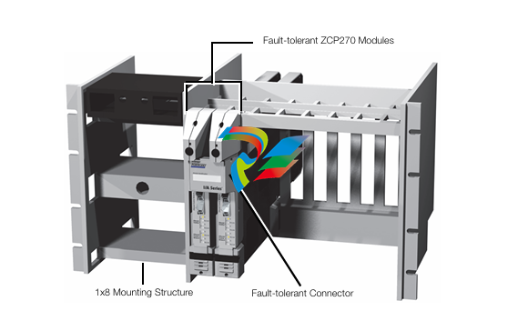 Foxboro P0972VA Industrial Control Module
 Foxboro Z-Module Control Processor 270 (ZCP270)
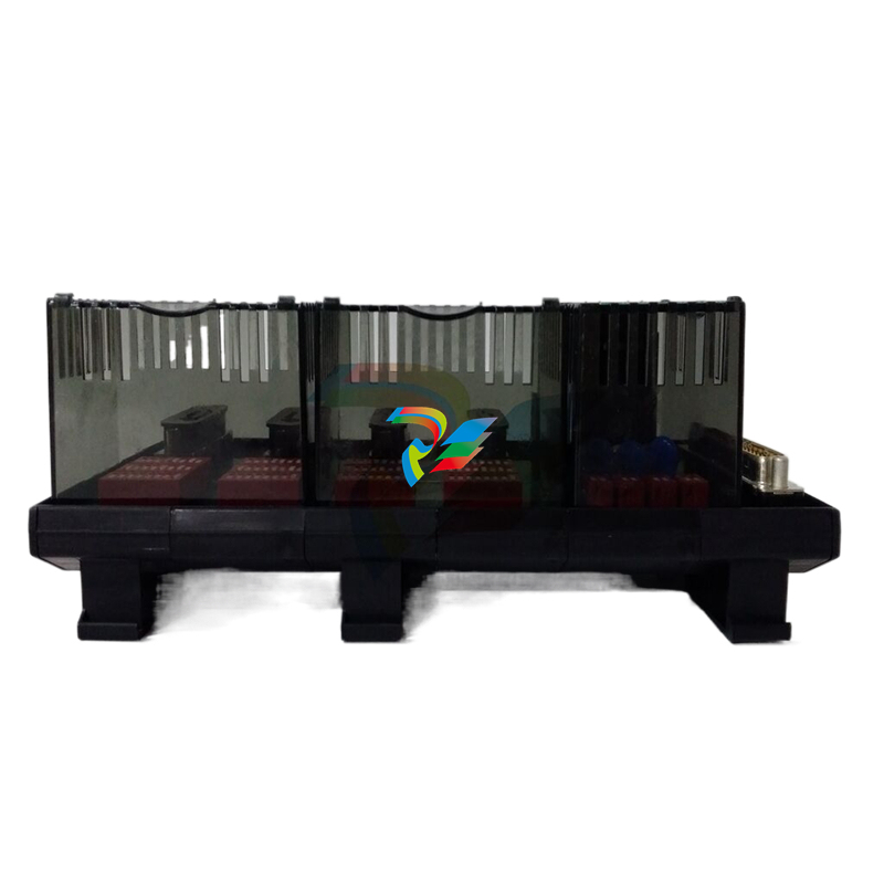 Foxboro PO916JS 16-channel terminal block module
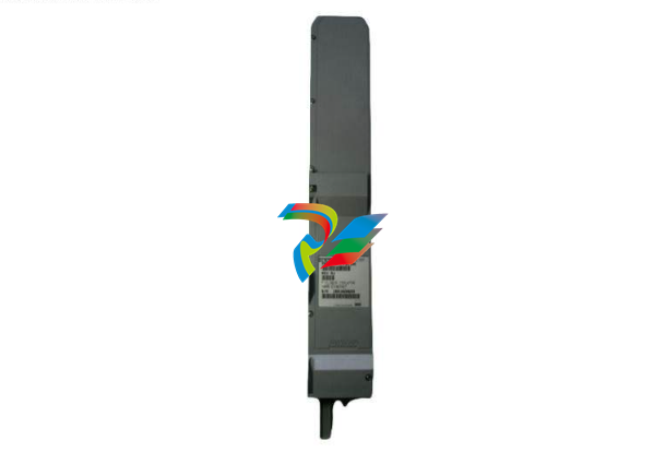 Foxboro PO911SM High-performance digital/analog input/output module
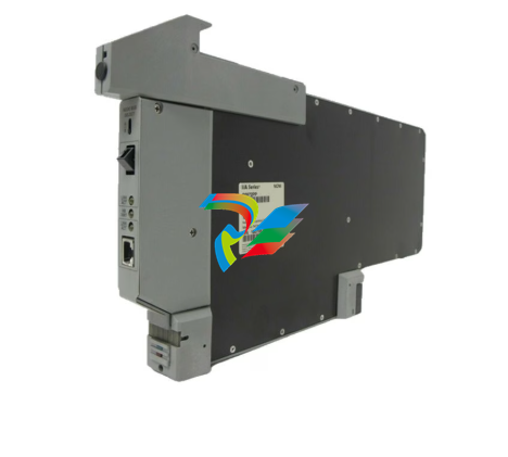 Foxboro P0972PP-NCNI Network Interface Module
.jpg) FOXBORO P0971QZ controller module
FOXBORO P0971QZ controller module FOXBORO P0971DP Thermal resistance input/output module
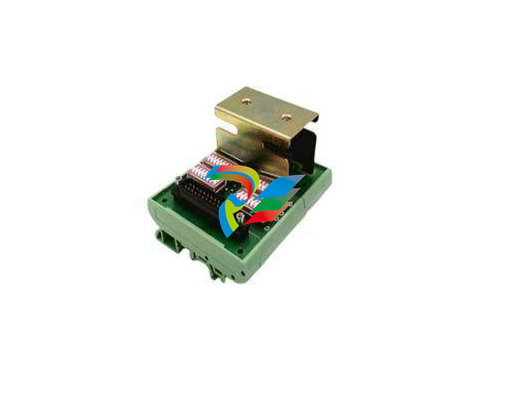 FOXBORO P0970VB Cable connector
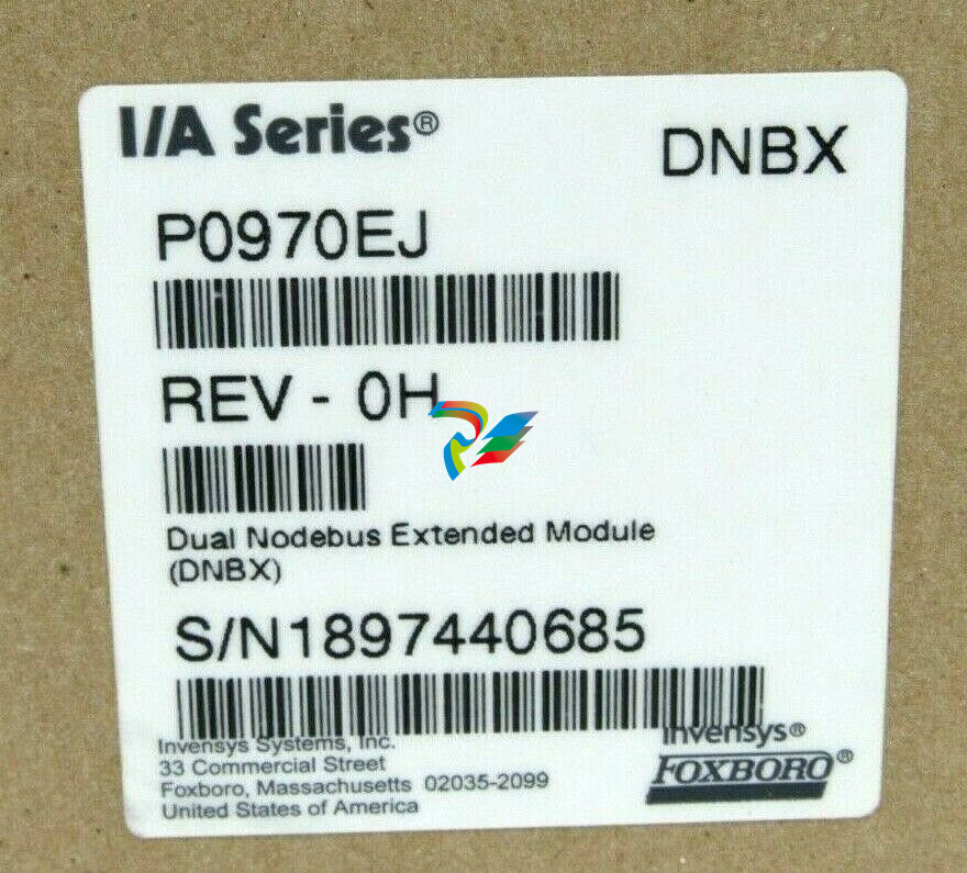 FOXBORO P0970EJ-DNBX Dual-node bus expansion module
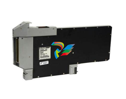 FOXBORO P0970BP Redundant power supply system
.jpg) FOXBORO P0970BC-DNBI DeviceNet bus interface module
FOXBORO P0970BC-DNBI DeviceNet bus interface module.jpg) FOXBORO P0961FX-CP60S Main control CPU module
FOXBORO P0961FX-CP60S Main control CPU module.jpg) FOXBORO P0961EF-CP30B Network Interface Unit
FOXBORO P0961EF-CP30B Network Interface Unit.jpg) FOXBORO P0961CA Optical fiber local area network module
FOXBORO P0961CA Optical fiber local area network module.jpg) FOXBORO P0961BD-GW30B gateway processor module
FOXBORO P0961BD-GW30B gateway processor module.jpg) FOXBORO P0961BC-CP40B/I/A Series high-performance control processor module
FOXBORO P0961BC-CP40B/I/A Series high-performance control processor module FOXBORO P0916BX Termination Assembly
.jpg) FOXBORO P0916AE P0916AG P0916AW Thermal resistance input type DCS card module
FOXBORO P0916AE P0916AG P0916AW Thermal resistance input type DCS card module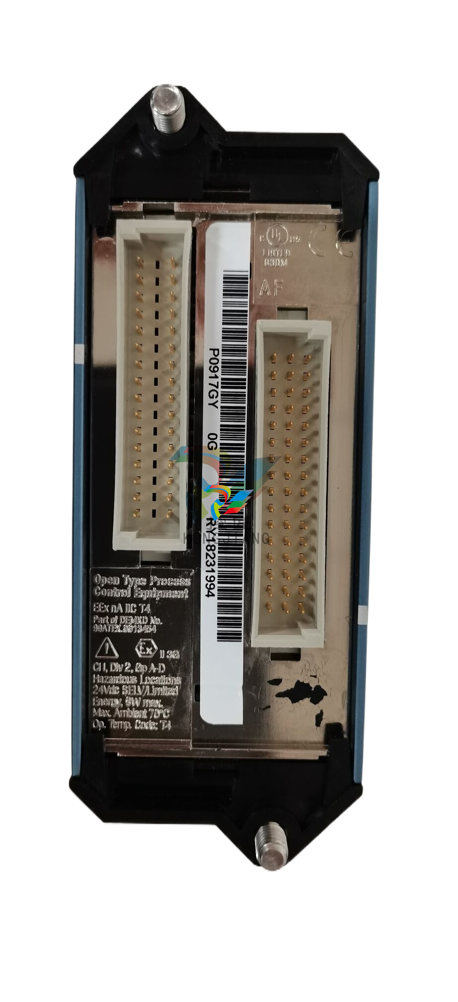 FOXBORO P0916AC FOXBORO distributed control system (DCS) compression terminal assembly
.jpg) FOXBORO P0912CB High-performance interface module
FOXBORO P0912CB High-performance interface module.jpg) FOXBORO P0911VJ Thermal resistance input output module
FOXBORO P0911VJ Thermal resistance input output module.jpg) FOXBORO P0911QH-A High-precision module
FOXBORO P0911QH-A High-precision module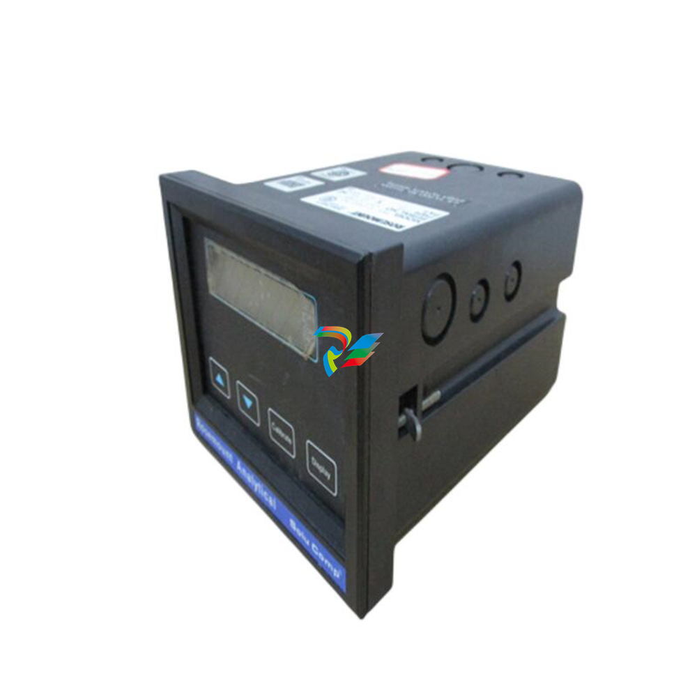 FOXBORO P0911QB-C P0911QC-C Thermal resistance input/output module
 FOXBORO P0904BH P0904FH P0904HB Distributed Control system (DCS) module
 FOXBORO P0903ZP P0903ZQ Embedded System Debugging Module
 Foxboro P0903ZL P0903ZN Industrial power module
 Foxboro P0903ZE I/A Series Fieldbus Isolator Module
 FOXBORO P0903NW Industrial Control Module

