
ABB 266 pressure transmitter
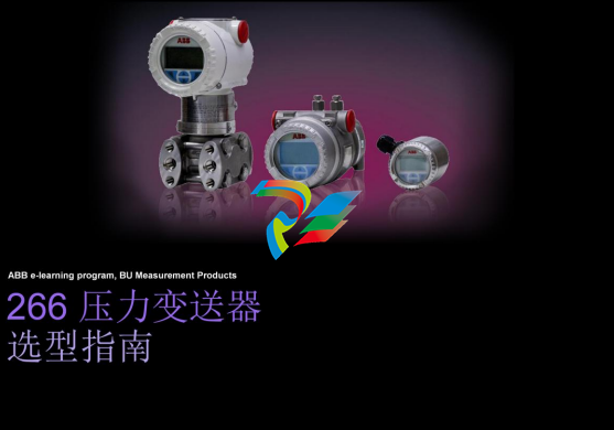 ABB MEASUREMENT & ANALY TICS | DATA SHEET
266DSH
Differential pressure transmitters
ABB MEASUREMENT & ANALY TICS | DATA SHEET
266DSH
Differential pressure transmitters
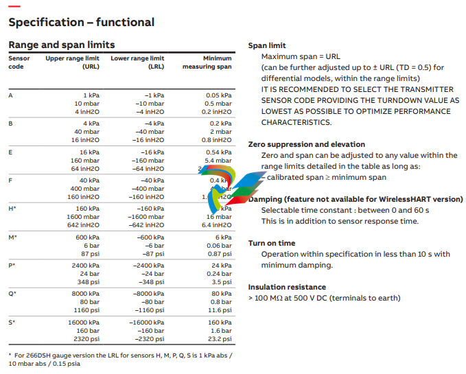
Measurement made easy Engineered solutions for all applications Base accuracy • from 0.06 % of calibrated span (optional 0.04 %) Reliable sensing system coupled with very latest digital technologies • provides large turn down ratio up to 100:1 Comprehensive sensor choice • optimize in-use total performance and stability 10–year stability • 0.15 % of URL Flexible configuration facilities • provided locally via local LCD keypad TTG (Through-The-Glass) keypad technology • allows quick and easy local configuration without opening the cover, even in explosion proof environments IEC 61508 certification • version for SIL2 (1oo1) and SIL3 (1oo2) applications PED compliance • Category III for PS > 20 MPa, 200 bar • Sound Engineering Practice (SEP) for PS ≤ 20 MPa, 200 bar WirelessHART version • the battery powered solution compliant to IEC 62591 Best-in-class battery life • up to 10 years @ 32 s update time • in-field replaceable Product in compliance with Directive 2011/65/UE (RoHS II) In-built advanced diagnostics 266DSH DIFFERENTIAL PRESSURE TRANSM
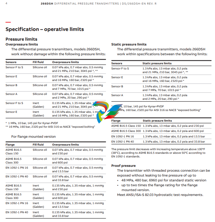
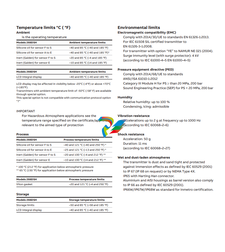
...Specification – operative limits Hazardous atmospheres (FOR ALL VERSIONS EXCEPT WirelessHART) With or without integral display INTRINSIC SAFETY Ex ia: • ATEX Europe (code E1) approval II 1 G Ex ia IIC T6...T4 Ga, II 1/2 G Ex ia IIC T6...T4 Ga/Gb, II 1 D Ex ia IIIC T85 °C Da, II 1/2 D Ex ia IIIC T85 °C Da; IP66, IP67. • IECEx (code E8) approval Ex ia IIC T6...T4 Ga/Gb, Ex ia IIIC T85 °C Da; IP66, IP67. • NEPSI China (code EY) Ex ia IIC T4/T5/T6 Ga, Ex ia IIC T4/T5/T6 Ga/Gb, Ex iaD 20 T85/T100/T135, Ex iaD 20/21 T85/T100/T135. EXPLOSION PROOF: • ATEX Europe (code E2) approval II 1/2 G Ex db IIC T6 Ga/Gb Ta=–50 °C to +75 °C, II 1/2 D Ex tb IIIC T85 °C Db Ta = –50 °C to +75 °C; IP66, IP67. • IECEx (code E9) approval Ex db IIC T6 Ga/Gb Ta=–50 °C to +75 °C, Ex tb IIIC T85 °C Db Ta = –50 °C to +75 °C; IP66, IP67. • NEPSI China (code EZ) Ex d IIC T6 Gb, Ex tD A21 IP67 T85 °C. INTRINSIC SAFETY Ex ic: • ATEX Europe (code E3 ) type examination II 3 G Ex ic IIC T6...T4 Gc, II 3 D Ex tc IIIC T85 °C Dc; IP66, IP67. • IECEx (code ER) type examination Ex ic IIC T6...T4 Gc, Ex tc IIIC T85 °C Dc; IP66, IP67. • NEPSI China (code ES) type examination Ex ic IIC T4~T6 Gc, Ex nA IIC T4~T6 Gc, Ex tD A22 IP67 T85 °C. FM Approvals US (code E6) and FM Approvals Canada (code E4): • Explosionproof (US): Class I, Division 1, Groups A, B, C, D; T5 • Explosionproof (Canada): Class I, Division 1, Groups B, C, D; T5 • Dust-ignitionproof: Class II, Division 1, Groups E, F, G; Class III, Div. 1; T5 • Flameproof (US): Class I, Zone 1 AEx d IIC T4 Gb • Flameproof (Canada): Class I, Zone 1 Ex d IIC T4 Gb • Nonincendive: Class I, Division 2, Groups A, B, C, D T6...T4 • Energy limited (US): Class I, Zone 2 AEx nC IIC T6...T4 • Energy limited (Canada): Class I, Zone 2 Ex nC IIC T6...T4 • Intrinsically safe:Class I, II, III, Division 1, Groups A, B, C, D, E, F, G T6...T4 Class I, Zone 0 AEx ia IIC T6...T4 (US) Class I, Zone 0 Ex ia IIC T6...T4 (Canada) Type 4X, IP66, IP67 for all above markings. COMBINED FM Approvals US and Canada • Intrinsically safe (code EA) COMBINED ATEX, FM and IECEx Approvals (code EN) Technical Regulations Customs Union EAC (Russia, Kazakhstan, Belarus), Inmetro (Brazil), Kosha (Korea) (ONLY FOR WirelessHART VERSION) With or without integral display INTRINSIC SAFETY Ex ia: • ATEX Europe (code E1) approval II 1 G Ex ia IIC T4 and II 1/2 G Ex ia IIC T4, IP67. • IECEx (code E8) approval Ex ia IIC T4 FM Approvals US and FM Approvals Canada: • Intrinsically safe:Class I, Division 1, Groups A, B, C, D; T4 Class I, Zone 0 AEx ia IIC T4 Gb (US) Class I, Zone 0 Ex ia IIC T4 Gb (Canada) IP67 for all above markings. IMPORTANT REFER TO CERTIFICATES FOR AMBIENT TEMPERATURE RANGES RELATED TO THE DIFFERENT TEMPERATURE CLASSES.
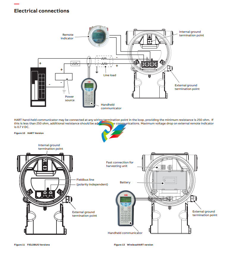
Electrical Characteristics and Options Optional indicators Integrated digital display (code LS; only with HART standard functionality) Wide screen LCD, 128 x 64 pixel, 52.5 x 27.2 mm (2.06 x 1.07 in.) dot matrix. Two keys for zero/span or without front push buttons when ordered with R1 external pushbuttons option Display may also indicate static pressure, sensor temperature and diagnostic messages. Integral display with integral keypad (code L1; not with HART standard functionality) Wide screen LCD, 128 x 64 pixel, 52.5 x 27.2 mm (2.06 x 1.07 in.) dot matrix. Multilanguage. Four keys for configuration and management of device. Easy setup for quick commissioning. User selectable application-specific visualizations. Totalized and instantaneous flow indication. Display may also indicate static pressure, sensor temperature and diagnostic messages and provides configuration facilities. Integral display with Through-The-Glass (TTG) activated keypad (code L5; not with HART standard functionality) As above integral display but equipped with the innovative TTG keypad allowing the activation of the configuration and management menus of the device without the need of removing the transmitter housing cover. TTG keypad is protected against accidental activations. Optional surge protection Up to 4kV • voltage 1.2 µs rise time / 50 µs delay time to half value • current 8 µs rise time / 20 µs delay time to half value Process diagnostics (PILD) Plugged impulse line detection (PILD) generates a warning via communication (HART, PA, FF). The device can be configured to drive the output to “Alarm current” or set a status “BAD”. HART® digital communication and 4 to 20 mA output – Standard and Advanced functionality Device type: 1a06hex (listed with HCF) Power supply The transmitter operates from 10.5 to 42 V DC with no load and is protected against reverse polarity connection (additional load allows operations over 42 V DC). For Ex ia and other intrinsically safe approval power supply must not exceed 30 V DC. Minimum operating voltage increases to 12.3 V DC with optional surge protector or to 10.8 V DC with optional conformity to NAMUR NE 21 (2004). Ripple 20 mV max on a 250 Ω load as per HART specifications. Load limitations 4 to 20 mA and HART total loop resistance : A minimum of 250 Ω is required for HART communication. Output signal Two–wire 4 to 20 mA, user-selectable for linear or square root output, power of 3 /2 or 5 /2 , square root for bidirectional flow, 22 points linearization table (i.e. for horizontal or spherical tank level measurement). HART® communication provides digital process variable superimposed on 4 to 20 mA signal, with protocol based on Bell 202 FSK standard. HART revision 7 is the default HART output. HART revision 5 is selectable on request. Output current limits (to NAMUR NE 43 standard) Overload condition • Lower limit: 3.8 mA (configurable from 3.8 to 4 mA) • Upper limit: 20.5 mA (configurable from 20 to 21 mA) Alarm current • Lower limit: 3.6 mA (configurable from 3.6 to 4 mA) • Upper limit: 21 mA (configurable from 20 to 23 mA, limited to 22 mA for HART Safety; apply for electronics release 7.1.15 or later) Factory setting: high alarm current
Electrical Characteristics and Options Optional indicators Integrated digital display (code LS; only with HART standard functionality) Wide screen LCD, 128 x 64 pixel, 52.5 x 27.2 mm (2.06 x 1.07 in.) dot matrix. Two keys for zero/span or without front push buttons when ordered with R1 external pushbuttons option Display may also indicate static pressure, sensor temperature and diagnostic messages. Integral display with integral keypad (code L1; not with HART standard functionality) Wide screen LCD, 128 x 64 pixel, 52.5 x 27.2 mm (2.06 x 1.07 in.) dot matrix. Multilanguage. Four keys for configuration and management of device. Easy setup for quick commissioning. User selectable application-specific visualizations. Totalized and instantaneous flow indication. Display may also indicate static pressure, sensor temperature and diagnostic messages and provides configuration facilities. Integral display with Through-The-Glass (TTG) activated keypad (code L5; not with HART standard functionality) As above integral display but equipped with the innovative TTG keypad allowing the activation of the configuration and management menus of the device without the need of removing the transmitter housing cover. TTG keypad is protected against accidental activations. Optional surge protection Up to 4kV • voltage 1.2 µs rise time / 50 µs delay time to half value • current 8 µs rise time / 20 µs delay time to half value Process diagnostics (PILD) Plugged impulse line detection (PILD) generates a warning via communication (HART, PA, FF). The device can be configured to drive the output to “Alarm current” or set a status “BAD”. HART® digital communication and 4 to 20 mA output – Standard and Advanced functionality Device type: 1a06hex (listed with HCF) Power supply The transmitter operates from 10.5 to 42 V DC with no load and is protected against reverse polarity connection (additional load allows operations over 42 V DC). For Ex ia and other intrinsically safe approval power supply must not exceed 30 V DC. Minimum operating voltage increases to 12.3 V DC with optional surge protector or to 10.8 V DC with optional conformity to NAMUR NE 21 (2004). Ripple 20 mV max on a 250 Ω load as per HART specifications. Load limitations 4 to 20 mA and HART total loop resistance : A minimum of 250 Ω is required for HART communication. Output signal Two–wire 4 to 20 mA, user-selectable for linear or square root output, power of 3 /2 or 5 /2 , square root for bidirectional flow, 22 points linearization table (i.e. for horizontal or spherical tank level measurement). HART® communication provides digital process variable superimposed on 4 to 20 mA signal, with protocol based on Bell 202 FSK standard. HART revision 7 is the default HART output. HART revision 5 is selectable on request. Output current limits (to NAMUR NE 43 standard) Overload condition • Lower limit: 3.8 mA (configurable from 3.8 to 4 mA) • Upper limit: 20.5 mA (configurable from 20 to 21 mA) Alarm current • Lower limit: 3.6 mA (configurable from 3.6 to 4 mA) • Upper limit: 21 mA (configurable from 20 to 23 mA, limited to 22 mA for HART Safety; apply for electronics release 7.1.15 or later) Factory setting: high alarm current
FOUNDATION FieldbusTM output Device type LINK MASTER DEVICE Link Active Scheduler (LAS) capability implemented. Manufacturer code: 000320hex Device type code: 0007hex Power supply The transmitter operates from 9 to 32 V DC, polarity independent, with or without surge protector. For Ex ia approval power supply must not exceed 24 V DC (FF–816 certification) or 17.5 V DC (FISCO certification). Current consumption operating (quiescent): 15 mA fault current limiting: 20 mA max. Output signal Physical layer in compliance to IEC 61158–2/EN 61158–2. Transmission to Manchester II modulation, at 31.25 kbit/s. Function blocks/execution period 3 enhanced Analog Input blocks/25 ms max (each) 1 enhanced PID block/40 ms max. 1 standard ARitmetic block/25 ms 1 standard Input Selector block/25 ms 1 standard Control Selector block/25 ms 1 standard Signal Characterization block/25 ms 1 standard Integrator/Totalizer block/25 ms Additional blocks 1 enhanced Resource block, 1 custom Pressure with calibration transducer block 1 custom Advanced Diagnostics transducer block including Plugged Input Line Detection 1 custom Local Display transducer block Number of link objects 35 Number of VCRs 35 Output interface FOUNDATION fieldbus digital communication protocol to standard H1, compliant to specification V. 1.7. Transmitter failure mode The output signal is “frozen” to the last valid value on gross transmitter failure condition, detected by selfdiagnostics which also indicate a BAD conditions. If electronic failure or short circuit occur the transmitter consumption is electronically limited at a defined value (20 mA approx), for safety of the network.
-
 Beckhoff C6640-0040 Control Cabinet Industrial PC 7-Slot
 -
 BECKHOFF CONTROL CABINET INDUSTRIAL PC - C6930-1062-0050
 -
 Beckhoff Automation EtherCAT Terminal EK1100 EK1122
 -
 Beckhoff CP6533-0001-0060 IPC
 -
 Beckhoff EK9500 | EtherNet/IP™ Bus Coupler
 -
 Beckhoff CP6202-1047-0050 - An industrial-grade embedded panel computer.
 -
 Beckhoff C6650-0040 Industrial PC
 -
 BECKHOFF CX5230-0185 / 000119805 PLC Module
 -
 BECKHOFF EL4732 | EtherCAT Terminal, 2-channel analog output, voltage, ±10 V, 16 bit, oversampling
 -
 Beckhoff CP6202-0001-0010 Economy Built-In Panel
 -
 Beckhoff AX5206-0000-0202 Digital Compact Servo Drives 2-channel
 -
 Beckhoff CP6606-0001-0020 7-inch Economy Panel PC
 -
 Beckhoff CPU basic module CX2020-0155 + power supply module CX2100-0004
 -
 Beckhoff CP2913-000 Multi-Touch Display
 -
 Beckhoff CP6500-1012-0060 14250369 Control Cabinet
 -
 Beckhoff CP7902-0001-0000 Economy Control Panel with DVI/USB Extended interface
 -
 Beckhoff C6920-0010 Control cabinet Industrial PC
 -
 BECKHOFF C3640-0050 Build-in Industrial PCs
 -
 Beckhoff KL6023-0000 KL6023 EnOcean Wireless-Adapter
 -
 Kollmorgen AKM54G-ANC2DB00 servo motor
 -
 Kollmorgen AKD-P00606-NBCN-0000 Servo Drive
 -
Kollmorgen S200 Series S20350-VTS SERVO DRIVE
-
 KOLLMORGEN AKD-P00606-NBCC-I000 SERVO DRIVE
 -
 Kollmorgen MV65WKS-CE310/22PB Servo Drive Control Module
 -
 Kollmorgen S20360-VTS-021 Servo Drive
 -
 KOLLMORGEN CR06550 High-precision digital servo amplifier
 -
 KOLLMORGEN DBL5N01050-03S-VV0-S40 3-Phase AC Synchronous Brushless Servo Motor
 -
 KOLLMORGEN S70301-NANANA-024 SERVO DRIVE
 -
 Kollmorgen S20360-VTS S200 Series Servo Drive
 -
 Kollmorgen RBE-03011-A00 Brushless Frameless Servo Motor
 -
 KOLLMORGEN AKD-T00306-NBAN-0000 INPUT SERVO DRIVE
 -
 KOLLMORGEN S700 Servo Controller S70302-NANANA
 -
 Kollmorgen AKD-P00607-NBEC-0000 400/480VAC 4.40KVA Servo Drive.
 -
 KOLLMORGEN S70102-NANANA SERVO DRIVE
 -
 KOLLMORGEN AKM21E-ANSNEH02 PM Servo Motor & PRD-AMPE25EB-00 Servo Drive Array
 -
 KollMorgen SC1R06260 Servo Drive 1.4/2.2 KVA 115230 Vac
 -
 Kollmorgen AKD-P00306-NBAN-0000 Servo Drive
 -
Kollmorgen TTB2-2042-3052-A DC Motor Industrial Drive 5.5A 185 oz/in
-
 KOLLMORGEN SERVOSTAR 610-AS SERVO AMPLIFIER_SERVOSTAR610AS_S61001
 -
 KOLLMORGEN PRD-0016400P-10 & PRD-0016600D-30 Axis Control System Modules
 -
KOLLMORGEN Seidel DBL5N01700-03S-000-S40 Servo Motor
-
 Hirschmann RS20-1600M2T1SDAEHH03.1.02 Rail Switch
 -
 Hirschmann BRS30-24TX Industrial Rail Switch
 -
 Hirschmann RSPM20-4T14T1EV9HHS999.9.99 Managed Ethernet Switch
 -
 Hirschmann BELDEN RS40-0009CCCCSDAPHH09.0.14 / RS400009CCCCSDAPHH09014
 -
Hirschmann RS40 Rail Switch RS40-0009CCCCSDAE
-
 Hirschmann BELDEN RS30-0802T1T1SDAP / RS300802T1T1SDAP Fully Managed Layer 2 Compact Rail Switch
 -
 Hirschmann BELDEN RS20-0800M2M2SDAUHH / RS200800M2M2SDAUHH
 -
 Hirschmann EAGLE30-04022O6TT999SCCY9HSE3F Industrial Firewall Router Switch
 -
 Hirschmann RS20-1600T1T1SDAEHH09.0.14 RS20 Rail Mount Ethernet Switch
 -
 Hirschmann EAGLE0200T1T1TDDY90000HHE05.3.03 Industrial Security Router
 -
Hirschmann - BELDEN MIPP-AD-1L9P
-
 HIRSCHMANN RSPM20-4Z64Z6TV9HHS9 942 106-999 RAIL SAFETY SWITCH
 -
 HIRSCHMANN FIBEROPTIC MODULE FIP P/N: OZDFIPG3T
 -
 HIRSCHMANN RS20-1600M2M2SDAUHH Ethernet rack-mounted switch
 -
 HIRSCHMANN BELDEN RS20-0400T1T1SDAEHH04.0.01 / RS200400T1T1SDAEHH04001
 -
HIRSCHMANN MM2-4FXM3 MICE Media Module
-
HIRSCHMANN RS20-0800M2M2SDAE Industrial Ethernet Rail Switch
-
 Hirschmann RS20-2400T1T1SDAP / RS20-2400T1T1SDAPHH05.0.02
 -
 GE MLJ1005B010H00C MLJ Digital Synchromism Check
 -
 ALSTOM MICROTECH DX21-M2 Digital Excitation Controller
 -
HIRSCHMANN BRS20-1200ZZZZ-STCY99HHSES
-
 HIRSCHMANN MM3-4FXM2 MICE Media Module
 -
Hirschmann RSB20-0800T1T1SAABHH 8Port ENet Rail Switch RSB20
-
 Hirschmann MACH102-8TP Ethernet Switch
 -
 SAACKE DDZ-M marine steam pressure atomizer
 -
 SAACKE SKV-A marine rotary cup atomizer
 -
 SAACKE Seavis HMI05e
 -
 Kollmorgen MMC-SD-2.0-230 Servo Drive 100-240VAC 2KW 10A Output 3PH 100-240VAC
 -
 Kollmorgen Servo drive CR10550
 -
 Kollmorgen AKD-P01207-NACN-0054 Servo Driver
 -
 Kollmorgen S406M-CA-036 Servostar
 -
.png) Kollmorgen AKD-B02407-NAAN-0000 Digital Servo Drive
Kollmorgen AKD-B02407-NAAN-0000 Digital Servo Drive -
 Kollmorgen SERVOSTAR S406AM-CA Digital Servo Drive
 -
 KOLLMORGEN SERVOSTAR 603-AS SERVO AMPLIFIER_SERVOSTAR603AS_S60301
 -
Kollmorgen S700 Servo Controller (S70602-NANANA-NA)
-
 Kollmorgen MPK411 controller
 -
 KOLLMORGEN MMC-SD-1.3-460-D Smart Drive
 -
 KOLLMORGEN AKM21C-CKB2AA-00 / AKM21CCKB2AA00 Servomotor
 -
 BECKHOFF AX5106-0000-0200 | Digital Compact Servo Drives 1-channel
 -
 BECKHOFF C3620-0000 INDUSTRIAL COMPUTER (MOTORSHELVES)
 -
 Beckhoff EK1960-0000 TwinSAFE Compact Controller
 -
 Beckhoff C6930-0050 Control Cabinet Industrial PC
 -
 Beckhoff CP7711-0001-0030 Industrial Computer Detection
 -
 Beckhoff CX1001-0111 Embedded PC CPU Module
 -
 Beckhoff C6017-0020 | Ultra-compact Industrial PC
 -
 Beckhoff EK1322 | 2-port EtherCAT P junction with feed-in
 -
 Beckhoff CP2219-0010 Panel
 -
 BECKHOFF C6015-0020 ULTRA COMPACT INDUSTRIAL PC
 -
 BECKHOFF CX2030-0120/Standard CPU Module Embedded PC Windows PLC controller
 -
 Beckhoff CP7721-1090-0020 Panel PC
 -
 Beckhoff PC CPU Module CX5130-0175
 -
 Beckhoff C6920-0050 Control Cabinet
 -
 Beckhoff EL6631 EtherCAT 2-Port Communication Interface, Profinet RT Controller
 -
 Beckhoff CP6202-0001-0060 touch screen panel PC
 -
 Beckhoff CP3916-1002-0000 Multi-Touch Control Panel
 -
 Beckhoff EP1809-0021 | EtherCAT Box, 16-channel digital input, 24 V DC, 3 ms, M8Preferred type
 -
 Beckhoff CX8190 PLC Embedded Industrial PC Ethernet Controller
 -
 Beckhoff CX2100-0914 Power Supply for External
 -
 Beckhoff Automation CP6906-0001-0000 HMI
 -
 Beckhoff EP7342-0002 Module
 -
 Beckhoff CX1020-0112 / CX1100-0910 / CX1020-N010 / CX1100-0003 Windows CPU
 -
 Beckhoff EP7211-0034 EtherCAT Box 1 Channel Motion Interface
 -
 Beckhoff C6240-0030 Control cabinet Industrial PC
 -
 beckhoff motherboard CB1052-0004 CB1052-0004
 -
 Beckhoff AX2006-AS Servo Drive / Variable Frequency Drive
 -
BECKHOFF CP6207-0001-0020 NSMP
-
 Beckhoff C6930-1142-0060 Industrial Computer
 -
 Beckhoff FC7501-0000 interface card
 -
 Beckhoff CX5140-0175 Embedded PC PLC CPU CX5140 Industrial Controller
 -
 Beckhoff CP7802-1100-0010: High-End IP65 Control Panel with DVI/USB Extended Interface
 -
BECKHOFF CP3716-1058-0010 CONTROL PANEL
-
 Beckhoff AX8108-0000 Single-Axis Module
 -
 Beckhoff CU8851-0000 | USB extension, USB Extended 2.0 receiver box
 -
Beckhoff C6017-0030 | Ultra-compact Industrial PC
-
 Beckhoff CX1001-0120/CX10010120.cx1000-n001.cx1000-n000 System Overview
 -
 Beckhoff CPU Module CX5140-0155/4GB CPU Module
 -
 Beckhoff CP6533-0001-005: Built-in Panel PC with High-Definition Multi-Touch Control
 -
 Beckhoff EL5042 | EtherCAT Terminal, 2-channel encoder interface, BiSS® C
 -
 Beckhoff C6920-1080-0040: Premium Control Cabinet Industrial PC
 -
 Beckhoff C6920-0060 | Control cabinet Industrial PC
 -
 Beckhoff Embedded-PC CX5010-1121
 -
 Beckhoff CB3050-0010 Mainboard Motherboard
 -
 Beckhoff PLC module CX1020-0000 Basic CPU module (service phase)
 -
 Beckhoff CP7812-1056-0010 15" Multitouch Display Control Panel
 -
 Beckhoff CX5120-0115 /2GB Controller Module
 -
 Beckhoff CP7201-1000-0000 Industrial Panel PC
 -
 Beckhoff Servo Motor AM8061-0JH1-0000


