ABBAO2000-LS25 Laser analyzers
1.5 Laser classification and warnings The diode lasers used in the analyzer operate in the near infrared (NIR) range between 700 and 2400 nm depending on the gas to be measured. Laser Class 1M for sample component O2 Laser Class 1 for all other sample components according to IEC 60825-1. NOTE: The lasers emit invisible light! WARNING: Class 1M Laser Product – Do not open when energized! Do not view directly with optical instruments! WARNING: Class 1 Laser Product – Do not open when energized!
2.1 Tools and other equipment The following equipment is necessary to install and calibrate the equipment:
2 pcs open-end spanners for M16 bolts
1 pcs Allen key 5 mm for the locking screws on flanges
1 pcs PC (386 or higher). Used during installation and calibration
1 pcs flat screwdriver 2.5 mm for electrical connections
Flow conditions at measuring point When deciding the placement of the analyzer in the process, we recommend a minimum of 5 stack diameters of straight duct before and 2 stack diameters of straight duct after the point of measure.
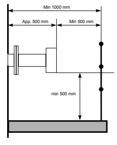
Monitor placement Both the transmitter and receiver units should be easily accessible. A person should be able to stand in front of either the transmitter unit or the receiver unit and adjust the M16 fixing bolts using two standard spanners. For the receiver unit there should be at least 1 m free space measured from the flange fixed to the stack and outwards as shown in Figure 2-1.

power is disconnected or switched off before connecting any cable. Please note that the power plug is the disconnecting device (no separate mains switch on instrument) and should be placed easily accessible for the operator. To install the instrument on the process follow the steps below.
Install transmitter alignment and purging unit (5) onto the stack flange with 4 pcs. M16x60 bolts (ref. Figure 3-4). All 4 bolts on either side must be tightened firmly to compress the large O-ring. Adjust the 4 locking screws prior to mounting the unit, to assure good alignment of the unit and a uniform compression of the O-ring. 2. Install pressurized instrument purging as described in Section
1.2. 3. Open the purging. Refer to Section 3.1.2 for details. 4
. Put the window adapter ring (4) on the alignment unit. Make sure that the O-ring on the alignment unit is tight and greased. The guiding pin on the alignment unit must fit the hole in the adapter ring.
. Affix an O-ring (not greased) to the adapter ring and connect the transmitter unit to the alignment unit. The guiding pin on the adapter ring must fit the hole in the transmitter window. Tighten the transmitter-mounting nut.
. Repeat steps 1-5 for the receiver unit.
. Connect the transmitter and receiver units with the corresponding cable (refer to Figure 6-1 for location of receiver connection on transmitter unit). All connectors are coded with small red pins on the inside.
. Connect external 4–20 mA temperature and pressure probes (ref. Section 6.3 and 6.5). This is optional as some instruments operate without probes. Input signals are connected to the terminals in the power supply unit or directly to the terminals in the main power connector at the transmitter unit. If connected to the power connector the factory-mounted wires should be removed from the terminals in question.
. Connect the transmitter and power supply units with the corresponding cable. The analyzer can now be switched on. This procedure is described in Section 3.2.
Air purging of flanges The instrument windows are kept clean by setting up a positive flow of air through the flanges and into the stack. This purging will prevent particles from settling on the optical windows and contaminating them. The purge gas must be dried and cleaned. We recommend using instrument air for purging. If instrument air is not available a separate blower is needed. A purge flow of approximately 20–50 l/min (process dependent) is sufficient for most installations. Alternatively, the initial velocity of the purge flow in the flanges is set to 1/10 of the gas velocity in the duct. After completion of the installation the purge flow is optimized as described in Section 5.3. The air quality should conform to standard set by ISO 8573.1, Class 2-3. This means particles down to 1 micron should be removed, including coalesced liquid water and oil, and a maximum allowed remaining oil aerosol content of 0.5 mg/m3 at 21C (instrument air). Note that some instruments require nitrogen purging, e.g. O2 instruments for high temperature or pressure applications, some H2O instruments etc.
Purging of transmitter and receiver units For applications where purging of transmitter and receiver units is required the direction of flow is illustrated in Figure 3-3. Since there are optical surfaces inside these units, the cleanness of the gas should be ensured and additional filtering may be necessary. Note that so called “instrument air” may contain some oil and water. If receiver and transmitter are purged with such air they can be permanently damaged after a short time. It is highly recommended to use nitrogen as a purge gas. The purge flow must not be high to avoid pressure build-up inside the units. We recommend reducing the flow to less than 0.5 l/min. If the flow is blocked the units can hold the gas to better than 99.5% during one hour


