
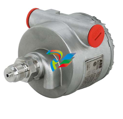
ABB266DSHDifferential pressure transmitters
Electrical Characteristics and Options Optional indicators Integrated digital display (code LS; only with HART standard functionality) Wide screen LCD, 128 x 64 pixel, 52.5 x 27.2 mm (2.06 x 1.07 in.) dot matrix. Two keys for zero/span or without front push buttons when ordered with R1 external pushbuttons option Display may also indicate static pressure, sensor temperature and diagnostic messages. Integral display with integral keypad (code L1; not with HART standard functionality) Wide scre
en LCD, 128 x 64 pixel, 52.5 x 27.2 mm (2.06 x 1.07 in.) dot matrix. Multilanguage. Four keys for configuration and management of device. Easy setup for quick commissioning. User selectable application-specific visualizations. Totalized and instantaneous flow indication. Display may also indicate static pressure, sensor temperature and diagnostic messages and provides configuration facilities. Integral display with Through-The-Glass (TTG) activated keypad (code L5; not with HART standard functionality) As above integral display but equipped with the innovative TTG keypad allowing the activation of the configuration and management menus of the device without the need of removing the transmitter housing cover. TTG keypad is protected against accidental activations. Optional surge protection Up to 4kV
• voltage 1.2 µs rise time / 50 µs delay time to half value
• current 8 µs rise time / 20 µs delay time to half value Process diagnostics (PILD) Plugged impulse line detection (PILD) generates a warning via communication (HART, PA, FF). The device can be configured to drive the output to “Alarm current” or set a status “BAD”. HART® digital communication and 4 to 20 mA output – Standard and Advanced functionality Device type: 1a06hex (listed with HCF) Power supply The transmitter operates from 10.5 to 42 V DC with no load and is protected against reverse polarity connection (additional load allows operations over 42 V DC). For Ex ia and other intrinsically safe approval power supply must not exceed 30 V DC. Mini
mum operating voltage increases to 12.3 V DC with optional surge protector or to 10.8 V DC with optional conformity to NAMUR NE 21 (2004). Ripple 20 mV max on a 250 Ω load as per HART specifications. Load limitations 4 to 20 mA and HART total loop resistance : A minimum of 250 Ω is required for HART communication. Output signal Two–wire 4 to 20 mA, user-selectable for linear or square root output, power of 3 /2 or 5 /2 , square root for bidirectional flow, 22 points linearization table (i.e. for horizontal or spherical tank level measurement). HART® communication provides digital process variable superimposed on 4 to 20 mA signal, with protocol based on Bell 202 FSK standard. HART revision 7 is the default HART output. HART revision 5 is selectable on request. Output current limits (to NAMUR NE 43 standard) Overload condition
• Lower limit: 3.8 mA (configurable from 3.8 to 4 mA)
• Upper limit: 20.5 mA (configurable from 20 to 21 mA) Alarm current
• Lower limit: 3.6 mA (configurable from 3.6 to 4 mA)
• Upper limit: 21 mA (configurable from 20 to 23 mA, limited to 22 mA for HART Safety; apply for electronics release 7.1.15 or later) Factory setting: high alarm current.
...Specification – electrical characteristics and options IEC 62591 WirelessHART® output Device type: 1a06hex (listed with HCF) Network ID: ABBhex (2747 decimal) Join keys: 57495245hex (1464422981) 4c455353hex (1279611731) 4649454chex (1179206988) 444b4559hex (1145783641). Power Supply 1x D-cell size lithium-thionyl chloride battery. Battery life: 10 years at 32 sec. update time, 8 years at 16 sec. update time or 5 years at 8 sec. update time. (at reference conditions of 25 ± 2 °C ambient temperature, data routed from 3 additional devices, LCD off). THE BATTERY CAN BE REPLACED IN FIELD, ALSO IN HAZARDOUS CLASSIFIED AREA. Output signal IEC 62591 WirelessHART Version 7.5 (IEEE 802.15.4-2006); Frequency band: 2.4 GHz DSSS Update rate: user selectable from 1 sec. to 60 min. Integrated adjustable omnidirectional antenna – O
utput radio frequency: maximum 10 mW (10 dBm) EIRP – Range: up to 300 m. (328 yds.) Minimum distance between antenna and person is 0.2 m. (8 in.) Telecommunications directive Every wireless measuring device must be certified in accordance with the telecommunications directive, in this case the frequency range. This certification is countryspecific. European directives Radio Equipment & Telecommunications Terminal Equipment Directive 2014/53/UE to standards EN 60950- 1:2013, EN 62311:2008, EN 301 489-1 V1.9.2, EN 301 489-17 V2.2.1, EN 300 328 v1.8.1. In Europe, use of the 2400 - 2483.5 MHz frequency band is not harmonized. Country-specific regulations must be observed. Restrictions for Norway Operation not permitted within a radius of 20 km around Ny-Alesund in Svalbard. For more information, see www.npt.no Norway Posts and T
elecommunications site Extra-european radio frequency licences USA to FCC Part 15.247:2009; Canada to IC RSS-210 and ICES-003; Argentina; United Arab Emirates (UAE); India; Mexico. PROFIBUS® PA output Device type Pressure transmitter compliant to Profiles 3.0.1 Identification number: 3450 (hex) Power supply The transmitter operates from 9 to 32 V DC , polarity independent, with or without surge protector. For Ex ia approval power supply must not exceed 17.5 V DC. Intrinsic safety installation according to FISCO model. Current consumption operating (quiescent): 15 mA fault current limiting: 20 mA max. Output signal Physical layer in compliance to IEC 1158–2/EN 61158–2 with transmission to Manchester II modulation, at 31.25 kbit/s. Output interface PROFIBUS
-
 OMRON C200PC-ISA02-DRM-E PLC ISA bus compatible board card
 -
 OMRON C500-CT012 PLC
 -
 OMRON C500-NC103-E PLC
 -
 OMRON C500-NC222-E PLC
 -
 OMRON C500-PRW05-V1 PLC
 -
 OMRON C500-PRW06 PROGRAMMABLE CONTROLLER
 -
 OMRON C500-PS223-E 3G2A5-PS223-E PLC SYSMAC PROGRAMMABLE CONTROLLER
 -
 OMRON C500-TU001 3G2A5-TU001 PLC PLC
 -
 OMRON C60H-C1DR-DE-V1 Programmable Controllers
 -
 OMRON C60H-C5DR-DE-V1 Programmable Controllers
 -
 OMRON C60H-C6DR-DE-V1 Programmable Controllers
 -
 OMRON CJ1G-CPU44H CPU module
 -
 OMRON CJ1G-CPU45H PLC
 -
 OMRON CJ1M-CPU13-ETN V4.0 PLC PLC
 -
 OMRON CJ1W-AD041-V1 Analog input uni
 -
 OMRON CJ1W-CORT21 PLC module
 -
 OMRON CJ1W-IDP01 Input unit
 -
 OMRON CJ1W-MCH71 - MECHATROLINK-II
 -
 OMRON CJ1W-MD261 Digital I/O
 -
 OMRON CJ1W-NC413 Position control unit
 -
 OMRON CJ1W-NCF71 Position Control Units
 -
 OMRON CJ1W-PTS51 Process Simulation I/O Module
 -
 OMRON CJ1W-PTS52 Process Simulation I/O Module
 -
 OMRON CJ1W-SCU21-V1 PLC
 -
 Omron CJ1W-SCU22 Serial Communication Unit
 -
 OMRON CJ1W-TC001 CJ Series Temperature Control Unit
 -
 Omron CK3W-AX1515N Motion Controller
 -
 Omron CP1E-N60DR-D Compact PLC CPU
 -
 OMRON CP1E-NA20DT1-D PLC PLC
 -
 OMRON CP1H-X40DT-D plc PLC
 -
 OMRON CPM2C-S110C-DRT Interface module
 -
 OMRON CQM1-AD041 PLC
 -
 SAACKE F‑GDSA‑1 / F‑GDSA‑2 Feuerungsautomaten
 -
 SAACKE F-GDSA 143303 Controller SHIPS UPS
 -
 ICS Triplex T8270 Trusted 24 Vdc FanAssembly
 -
 SCHNEIDER M522220000 SA SM_DO16R 16 DIGITAL OUTPUTS MODULE
 -
 LENZ EPL10200-W EPZ-10203 CANPT010W3E
 -
 OMRON CQM1H-ADB21 PLC
 -
OMRON CQM1H-CPU61 PLC
-
 OMRON CQM1H-MAB42 PLC
 -
 OMRON CQM1-TC102 CQM1-TC101 PLC
 -
 OMRON CS1G-CPU44-EV1 PLC
 -
 OMRON CS1G-CPU44H CPU
 -
OMRON CS1H-CPU63-EV1 PLC
-
 OMRON CS1H-CPU66-V1 PLC
 -
 OMRON CS1W-CLK13 PLC communication module
 -
OMRON CS1W-EIP21 PLC
-
 OMRON CS1W-MAD44 PLC PLC
 -
 OMRON CS1W-SCU31-V1 CVM1-BC103 PLC
 -
 Omron CVM1-CPU21-V2 CPU Unit
 -
 OMRON F150-C10E-2 Vision Controller
 -
 OMRON F150-C15E-3 Vision Controller
 -
 OMRON F160-C15E VISION MATE CONTROLLER
 -
 OMRON F500-C10-ETN F500-C15-ETN Vision Sensor
 -
 OMRON F500-VS F500-S1
 -
 OMRON FH-3050 FH Vision Controller
 -
 Omron FQ2-S25050F PLC Smart Camera
 -
 Omron FQM1-MMA22 Motion Module
 -
 OMRON GRT1-TS2P Temperature Module
 -
 OMRON H8PR-24 Cam Positioner
 -
 OMRON IDSC-C1DR-A-E Controller
 -
 OMRON K3HB-HTA-DRT1 Temperature Panel Meter
 -
 Omron KM-N1-FLK Power Detector
 -
 OMRON CJ1G-CPU43H CPU
 -
 OMRON NA5-7W001S-V1 NA5-9W001B-V1 NA5-12W101B-V1 Graphic panel
 -
 OMRON NA5-9W001B-V1 Graphic panel
 -
 OMRON NB10W-TW01B INTERACTIVE DISPLAY
 -
 OMRON NB7W-TW01B +CP1L-EL20DR-D Complete Power Panel
 -
 OMRON NB7W-TX01B INTERACTIVE DISPLAY PLC
 -
 Omron NE1A-SCPU02 Network Controller
 -
 OMRON NA5-7W001B-V1 NA5-7W001S-V1 NA5-9W001B-V1 NA5-12W101B-V1 touch screen
 -
 Omron NS5-SQ00B-V2 NS5-SQ00-V2 NS5-SQ01-V2 NS5-SQ01B-V2 touch display panel
 -
 Omron NJ301-1100 Programmable Logic Controller
 -
 OMRON NJ501-1300 CUP Unit Programmable Controller
 -
 Omron NS12-TS01B-V2 Interactive Display
 -
 OMRON NSJW-ETN21 ETHERNET HMI
 -
 OMRON NT10S-SF121 PLC
 -
 OMRON NT20S-ST121-EV3 Touch Screen
 -
 Omron NX1P2-1140DT-BA Programmable Controller
 -
 OMRON 3G3MV-P10CDT3-E RS422/485 INVERTER BOARD
 -
 Omron C500-ID219 3G2A5-ID219 System Microprocessor
 -
 Omron PLC B7AM-8B16
 -
 OMRON PLC Module CJ1W-AD081-V1
 -
 OMRON R88D-HS10 PLC
 -
OMRON R88D-HT10 plc
-
 OMRON R88D-KN01H-ML2 Servos G5-series
 -
 OMRON R88M-H10030-B plc
 -
 OMRON R88S-H306G plc PLC
 -
 Omron Relay G9SX-GS226-T15-RT
 -
 Omron S8AS-24006N S8AS Smart Power Supply FNIP
 -
 Omron Safety Input Unit NX-SIH400
 -
 OMRON SYSMAC SCY-P1 Sequential Controller
 -
OMRON SYSMAC SCY-P0 13E Sequential Controller
-
 OMRON NS8-TV00B-V2 NS8-TV00-V2 NS8-TV00B-ECV2 NS8-TV00-ECV2 touch display Panel
 -
 Omron V680-CA5D02-V2 Programmable Controller
 -
 OMRON SGDH-04AE-OY Servo Drive
 -
OMRON SGDH-10DE-OY Servo Drive
-
 OMRON SGDS-02A12A PLC + SGMAS-C2ACA21
 -
 OMRON SGMPH-04AAA61D-OY Servo Motor
 -
 Omron ZFV-CA40 Smart Sensor Amp Unit 24VDC 0.8A
 -
OMRON ZFV-NX1 CFP0260 ZFV-A20 VISION CONTROL PANEL
-
 OMRON ZFX-C15 SMART SENSOR AMP UNIT, Vision Sensor LCD
 -
 OMRON ZFX-C20/25-CD SMART SENSOR AMP UNIT, Vision Sensor LCD
 -
 OMRON-DIGITAL TEMPERATURE CONTROLLER E5AC-CX4A5M-014 r
 -
 ABB PFVL141V-2.0MN is an industrial-grade, rectangular roll force load cell
 -
 ABB PFVL141V-1.6MN is an industrial-grade, rectangular roll force load cell
 -
ABB PFVL141V-1.25MN high-performance, rectangular roll force load cell
-
 ABB PFVL141V-1.0MN high-precision, heavy-duty rectangular load cell
 -
 ABB PFVL141V-0.8MN high-precision, heavy-duty rectangular load cell
 -
 ABB PFVL141V-0.63MN high-precision, heavy-duty rectangular load cell
 -
 GE 151X1202YE08PP08 Panel of the case / Structural component
 -
 GE 151X1212HB01MG02 Integrated LCI Controller (Old Model)
 -
 GE 151X1212GC01PC02 LCI Static Startup Controller
 -
 GE 151X1235FD01PK01 High-speed Digital Input Interface Board
 -
 GE 151X1215DK01PC01 Signal Processing / Amplification Board
 -
 GE 151X1238WP99BK01 6-pulse LCI power conversion module
 -
 GE 151X1225DF01PC03RA - Power Conversion / Drive Regulation Board
 -
 GE 151X1225DE03PC01 Drive Control Board (Terminal Control)
 -
 GE 151X1215GD01SA21 Gate Driver Board
 -
 GE 151X1235BC11WK01 - Network Management Industrial Switch (10/100M)
 -
 GE 151X1235BC01SA41 Enhanced 10-port switch (redundant)
 -
GE 151X1235BC01SA01 10 Industrial Ethernet Switches
-
 GE 151X1235DC85PC08 High-speed Digital Input Card (32DI)
 -
 GE 151X1233DB01SA01R4 Wind turbine pitch control I/O blue box
 -
 GE 151X1235DB01SA01 16DI+16DO I/O Panel
 -
 ABB 3BUS213621-001 SBC Assembly
 -
 ABB 3BUS212310-002 WEIGHT xP V2 DILUTION DRIVE MODULE
 -
 ABB U3BUS212310-001 Weight xPV2 Slice Drive Module


