
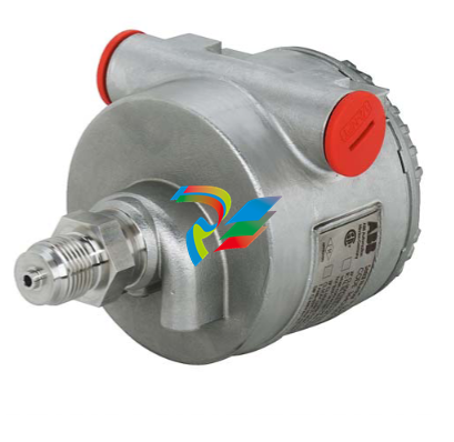
ABB266DSHDifferential pressure transmitters
Electrical Characteristics and Options Optional indicators Integrated digital display (code LS; only with HART standard functionality) Wide screen LCD, 128 x 64 pixel, 52.5 x 27.2 mm (2.06 x 1.07 in.) dot matrix. Two keys for zero/span or without front push buttons when ordered with R1 external pushbuttons option Display may also indicate static pressure, sensor temperature and diagnostic messages. Integral display with integral keypad (code L1; not with HART standard functionality) Wide scre
en LCD, 128 x 64 pixel, 52.5 x 27.2 mm (2.06 x 1.07 in.) dot matrix. Multilanguage. Four keys for configuration and management of device. Easy setup for quick commissioning. User selectable application-specific visualizations. Totalized and instantaneous flow indication. Display may also indicate static pressure, sensor temperature and diagnostic messages and provides configuration facilities. Integral display with Through-The-Glass (TTG) activated keypad (code L5; not with HART standard functionality) As above integral display but equipped with the innovative TTG keypad allowing the activation of the configuration and management menus of the device without the need of removing the transmitter housing cover. TTG keypad is protected against accidental activations. Optional surge protection Up to 4kV
• voltage 1.2 µs rise time / 50 µs delay time to half value
• current 8 µs rise time / 20 µs delay time to half value Process diagnostics (PILD) Plugged impulse line detection (PILD) generates a warning via communication (HART, PA, FF). The device can be configured to drive the output to “Alarm current” or set a status “BAD”. HART® digital communication and 4 to 20 mA output – Standard and Advanced functionality Device type: 1a06hex (listed with HCF) Power supply The transmitter operates from 10.5 to 42 V DC with no load and is protected against reverse polarity connection (additional load allows operations over 42 V DC). For Ex ia and other intrinsically safe approval power supply must not exceed 30 V DC. Mini
mum operating voltage increases to 12.3 V DC with optional surge protector or to 10.8 V DC with optional conformity to NAMUR NE 21 (2004). Ripple 20 mV max on a 250 Ω load as per HART specifications. Load limitations 4 to 20 mA and HART total loop resistance : A minimum of 250 Ω is required for HART communication. Output signal Two–wire 4 to 20 mA, user-selectable for linear or square root output, power of 3 /2 or 5 /2 , square root for bidirectional flow, 22 points linearization table (i.e. for horizontal or spherical tank level measurement). HART® communication provides digital process variable superimposed on 4 to 20 mA signal, with protocol based on Bell 202 FSK standard. HART revision 7 is the default HART output. HART revision 5 is selectable on request. Output current limits (to NAMUR NE 43 standard) Overload condition
• Lower limit: 3.8 mA (configurable from 3.8 to 4 mA)
• Upper limit: 20.5 mA (configurable from 20 to 21 mA) Alarm current
• Lower limit: 3.6 mA (configurable from 3.6 to 4 mA)
• Upper limit: 21 mA (configurable from 20 to 23 mA, limited to 22 mA for HART Safety; apply for electronics release 7.1.15 or later) Factory setting: high alarm current.
...Specification – electrical characteristics and options IEC 62591 WirelessHART® output Device type: 1a06hex (listed with HCF) Network ID: ABBhex (2747 decimal) Join keys: 57495245hex (1464422981) 4c455353hex (1279611731) 4649454chex (1179206988) 444b4559hex (1145783641). Power Supply 1x D-cell size lithium-thionyl chloride battery. Battery life: 10 years at 32 sec. update time, 8 years at 16 sec. update time or 5 years at 8 sec. update time. (at reference conditions of 25 ± 2 °C ambient temperature, data routed from 3 additional devices, LCD off). THE BATTERY CAN BE REPLACED IN FIELD, ALSO IN HAZARDOUS CLASSIFIED AREA. Output signal IEC 62591 WirelessHART Version 7.5 (IEEE 802.15.4-2006); Frequency band: 2.4 GHz DSSS Update rate: user selectable from 1 sec. to 60 min. Integrated adjustable omnidirectional antenna – O
utput radio frequency: maximum 10 mW (10 dBm) EIRP – Range: up to 300 m. (328 yds.) Minimum distance between antenna and person is 0.2 m. (8 in.) Telecommunications directive Every wireless measuring device must be certified in accordance with the telecommunications directive, in this case the frequency range. This certification is countryspecific. European directives Radio Equipment & Telecommunications Terminal Equipment Directive 2014/53/UE to standards EN 60950- 1:2013, EN 62311:2008, EN 301 489-1 V1.9.2, EN 301 489-17 V2.2.1, EN 300 328 v1.8.1. In Europe, use of the 2400 - 2483.5 MHz frequency band is not harmonized. Country-specific regulations must be observed. Restrictions for Norway Operation not permitted within a radius of 20 km around Ny-Alesund in Svalbard. For more information, see www.npt.no Norway Posts and T
elecommunications site Extra-european radio frequency licences USA to FCC Part 15.247:2009; Canada to IC RSS-210 and ICES-003; Argentina; United Arab Emirates (UAE); India; Mexico. PROFIBUS® PA output Device type Pressure transmitter compliant to Profiles 3.0.1 Identification number: 3450 (hex) Power supply The transmitter operates from 9 to 32 V DC , polarity independent, with or without surge protector. For Ex ia approval power supply must not exceed 17.5 V DC. Intrinsic safety installation according to FISCO model. Current consumption operating (quiescent): 15 mA fault current limiting: 20 mA max. Output signal Physical layer in compliance to IEC 1158–2/EN 61158–2 with transmission to Manchester II modulation, at 31.25 kbit/s. Output interface PROFIBUS
PA communication according to Profibus DP50170 Part 2/DIN 19245 part 1–3. Output update time 25 ms Data blocks 3 analog input, 1 physical. Additional blocks 1 Pressure with calibration transducer block 1 Advanced Diagnostics transducer block including Plugged Input Line Detection 1 Local Display transducer block Transmitter failure mode On gross transmitter failure condition, detected by selfdiagnostics, the output signal can be driven to defined conditions, selectable by the user as safe, last valid or calculated value. If electronic failure or short circuit occur the transmitter consumption is electronically limited at a defined value (20 mA approx), for safety of the network.
FOUNDATION FieldbusTM output Device type LINK MASTER DEVICE Link Active Scheduler (LAS) capability implemented. Manufacturer code: 000320hex Device type code: 0007hex Power supply The transmitter operates from 9 to 32 V DC, polarity independent, with or without surge protector. For Ex ia approval power supply must not exceed 24 V DC (FF–816 certification) or 17.5 V DC (FISCO certification). Current consumption operating (quiescent): 15 mA fault current limiting: 20 mA max. Output signal Physical layer in compliance to IEC 61158–2/EN 61158–2. Transmission to Manchester II modulation, at 31.25 kbit/s. Function blocks/execution period 3 enhanced Analog Input blocks/25 ms max (each) 1 enhanced PID block/40 ms max. 1 standard ARitmetic block/25 ms 1 standard Input Selector block/25 ms 1 standard Control Selector block/25 ms 1 standard Signal Characterization block/25 ms 1 standard Integrator/Totalizer block/25 ms Additional blocks 1 enhanced Resource block, 1 custom Pressure with calibration transducer block 1 custom Advanced Diagnostics transducer block including Plugged Input Line Detection 1 custom Local Display transducer block Number of link objects 35 Number of VCRs 35
Output interface FOUNDATION fieldbus digital communication protocol to standard H1, compliant to specification V. 1.7. Transmitter failure mode The output signal is “frozen” to the last valid value on gross transmitter failure condition, detected by selfdiagnostics which also indicate a BAD conditions. If electronic failure or short circuit occur the transmitter consumption is electronically limited at a defined value (20 mA approx), for safety of the network.
-
 AEROTECH BLMUC-143 Linear motor forcer with thermistor
 -
AEROTECH BLMUC-111 Linear motor forcer with thermistor
-
AEROTECH BLMUC-95 Linear motor forcer with thermistor
-
AEROTECH BLMUC-79 Linear motor forcer with thermistor
-
AEROTECH BLMUC Series Linear Motors
-
 AEROTECH Automation1 FLEX Distributed Amplifier Multi-Axis Servo Control System
 -
 AEROTECH Automation1 HXA4 6-Axis Hexapod Servo Drive
 -
 AEROTECH Automation1 iHXA4 6-Axis Hexapod Servo Drive with Motion Controller
 -
 AEROTECH Modular System Control Console
 -
 AEROTECH TV Series Transformers
 -
 AEROTECH TM Series Transformers
 -
 AEROTECH UFM Noise Filter Module
 -
 AEROTECH MFM Motor Filter Module
 -
 AEROTECH MPG Handwheel Pendant
 -
 AEROTECH Automation1 Multi-Axis Joystick
 -
 AEROTECH ETM Enhanced Throughput Module
 -
 AEROTECH Automation1 XL4s High-Speed, Single-Phase Linear Servo Drive
 -
 AEROTECH Automation1 XL2e Enhanced, Compact Linear Servo Drive
 -
 Automation1 iXL2e Enhanced, Compact Linear Servo Drive with Motion Controller
 -
 AEROTECH Automation1 XL5e Enhanced, Linear Servo Drive
 -
 AEROTECH Automation1 iXL5e Enhanced Linear Servo Drive with Motion Controller
 -
 AEROTECH Automation1 GI4 Laser Scan Head Controller
 -
 AEROTECH Automation1 SI4 Stepper Interface
 -
AEROTECH Automation1 XI4 Servo Interface
-
 AEROTECH AEROTECH Automation1 iXI4 Servo Interface with Motion Controller
 -
 AEROTECH Automation1 XC6e Enhanced, High-Power PWM Servo Drive
 -
 AEROTECH Automation1 iXC6e Enhanced, High-Power PWM Servo Drive with Motion Controller
 -
 AEROTECH Automation1 XC2 Compact PWM Servo Drive
 -
 AEROTECH Automation1 XC4 PWM Servo Drive
 -
 AEROTECH Automation1 GL4 Galvo Laser Scan Head Linear Drive
 -
 AEROTECH Automation1 XC2e Enhanced, Compact Servo Drive with PWM+
 -
 AEROTECH Automation1 XC4e Enhanced, PWM Servo Drive
 -
 AEROTECH Automation1 XR3 Multi-Axis Servo Drive Rack
 -
 AEROTECH Automation1 iXR3 Multi-Axis Servo Drive Rack with Motion Controller
 -
 AEROTECH Automation1 iXC2 Compact PWM Servo Drive with Motion Controller
 -
 AEROTECH Automation1 iXC2e Enhanced, Compact PWM+ Servo Drive with Motion Controller
 -
 AEROTECH Automation1 iXC4 PWM Servo Drive with Motion Controller
 -
 AEROTECH Automation1 iXC4e Enhanced, PWM Servo Drive with Motion Controller
 -
 AEROTECH Automation1 iPC Industrial PC with Motion Controller
 -
 AEROTECH EPICS & TANGO Drivers for Distributed Control Systems
 -
 AEROTECH .NET, C, Python & LabVIEW APIs Custom Application Develotpmen
 -
 AEROTECH Automation1 Industrial Ethernet Support
 -
 AEROTECH Automation1 iSMC Intelligent, Software-Based Motion Controller
 -
 AEROTECH Automation1 iXA4 1- 2- or 4-Axis PWM Servo Drive with Motion Controller
 -
 AEROTECH Automation1 XA4 1- 2- or 4-Axis PWM Servo Drive
 -
 CTI 2500-ADP2-DISC Discrete Wiring Adapter for Series 500
 -
 CTI 2500-ADP1 Analog Wiring Adapter for Series 500
 -
 CTI 2500C-RADP-RS485 Remote Base Controller Adapter for Series 500
 -
 CTI 2500C-RADP-RBC Profibus RBC Adapter for Series 500
 -
 CTI 2500C-PADP-120V 120VAC 50W Power Supply for Series 500
 -
 CTI 2500-RADP RBC Adapter for Series 500
 -
 CTI 2500-R4500 520/530/DBC Adapter for Series 500 - MATURE
 -
 CTI 2500-PADP Power Supply Adapter for Series 500
 -
 CTI 2500-IADP I/O Adapter for Series 500
 -
 CTI 2500-VP15A-N4-W7 15" Flat-Panel PC with Windows® 7 Embedded
 -
 CTI 2500S-27-1750 Slice I/O, Ethernet, RS232/485. 900MHz, 2DIO / 4UAI / 2AI
 -
 CTI 2500S-26-1750 Slice I/O, Ethernet, RS232/485. 900MHz, 8DIO / 2UAI
 -
 CTI 2500S-23-1750 Slice I/O, Ethernet, RS232/485. 900MHz, 4DI / 4DO / 2UAI / 2AO
 -
 CTI 2500S-27-1550 Slice I/O, RS232/485. 2DIO / 4UAI / 2AI
 -
 CTI 2500S-26-1550 Slice I/O, RS232/485. 8DIO / 2UAI
 -
 CTI 2500S-23-1550 Slice I/O, RS232/485. 4DI / 4DO / 2UAI / 2AO
 -
 CTI 2500S-27-1050 Slice I/O, Ethernet, 2DIO / 4UAI / 2AI
 -
 CTI 2500S-26-1050 Slice I/O, Ethernet, 8DIO / 2UAI
 -
 CTI 2500S-23-1050 Slice I/O, Ethernet, 4DI / 4DO / 2UAI / 2AO
 -
 CTI 2500C-32F-CJC 32-Pin Field Wiring Connector with Cold Junction Compensation
 -
 CTI 2500C-32F 32-Pin Field Wiring Connector
 -
 CTI 2500C-8-TC Eight Thermocouple Inputs
 -
 CTI 2500C-8-RTD Eight RTD Inputs
 -
 CTI 2500C-8-RL-FC 8 Form-C Relay Outputs
 -
 CTI 2500C-8-IDO-24V 8 Isolated 24VDC Outputs
 -
 CTI 2500C-8-IDO-120V 8 Isolated 120VAC Outputs
 -
 CTI 2500C-16-DO-24V Sixteen 24VDC Digital Outputs
 -
 CTI 2500C-16-DO-120V Sixteen 120VAC Digital Outputs
 -
.png) CTI 500C-16-IDI-24V Sixteen Isolated 24V AC/DC Digital Inputs
CTI 500C-16-IDI-24V Sixteen Isolated 24V AC/DC Digital Inputs -
 CTI 2500C-16-IDI-120V Sixteen Isolated 120V AC/DC Digital Inputs
 -
 CTI 2500C-16-DIDO-SIM Sixteen Digital Input and Output SImulator
 -
 CTI 2500C-16-DI-24V Sixteen 24V AC/DC Digital Inputs
 -
 CTI 2500C-16-DI-120V Sixteen 120V AC/DC Digital Inputs
 -
 CTI 2500C-RBC-RS485 RS485 Remote Base Controller
 -
 CTI 2500C-RBC-PRF Profibus Remote Base Controller
 -
 CTI 2500C-PS-24V-35 35-Watt DC Power Supply
 -
 CTI 2500C-PS-120V-35 35-Watt AC Power Supply
 -
 CTI 2500C-R8 Eight-Slot Base
 -
 CTI 2500C-R4 Four-Slot Base
 -
 CTI 2500C-R16 Sixteen-Slot Base
 -
 CTI 2500C-2572-B Fast Ethernet TCP/IP Adapter
 -
 CTI 2500C-J750 Compact Janus PAC with 3MB Project Memory
 -
 CTI 2500C-C300 CPU with 512K User Memory
 -
 CTI 2500C-C200 CPU with 256K User Memory
 -
 CTI 2500C-C100 CPU with 128K User Memory
 -
 CTI 2500C-8-AO 8 Analog Outputs
 -
 CTI 2500C-8-AI 8 Analog Inputs
 -
 CTI 2559-FCAL Precision Calibration Connector
 -
 CTI 2559-FPC 40-Position Screw-Terminal Connector
 -
 CTI 2500-RFC PLC to RF Modem Cable
 -
 CTI 2500-40F 40-Position Standard Screw-Terminal Connector
 -
 CTI 2505 Vibration Sensor Interface Module
 -
 CTI 2554-A 4-Channel Isolated High Speed Counter Module
 -
 CTI 2553-A 2-Channel Mag Meter Input Module
 -
 CTI 2502 2-Channel High Speed Counter Input Module
 -
 CTI 2559-TC 8-Channel Thermocouple Input Module
 -
 CTI 2556-A 16-Channel Isolated Thermocouple Input Module
 -
 CTI 2556 16-Channel Isolated Thermocouple Input Module
 -
 CTI 2551-A 8-Channel Isolated Thermocouple Input Module
 -
 CTI 2559-RTD 8-Channel RTD Input Module
 -
 CTI 2557-A 16-Channel RTD Input Module
 -
 CTI 2557 16-Channel RTD Input Module
 -
 CTI 2552-A 8-Channel Isolated RTD Input Module
 -
 CTI 2534 8-Point Form-C Relay Output Module
 -
 CTI 2532 16-Point Form-A Relay Output Module
 -
 CTI 2531 32-Point Form-A Relay Output Module
 -
 CTI 2530 8-Point Form-C Relay Output Module
 -
 CTI 2562 8-Channel Analog Output Module
 -
 CTI 2560-A 8-Channel Isolated Analog Output Module
 -
 CTI 2501 8in/4out Analog Module
 -
 CTI 2558 8-Channel Analog Input Module
 -
 CTI 2555-A 16-Channel Analog Input Module
 -
 CTI 2550-A 8-Channel Isolated Analog Input Module
 -
 CTI 2599 8/16/32-Point AC Output Module
 -
 CTI 2598-8 8-Point AC Output Module
 -
 CTI 2598 8/16-Point AC Output Module
 -
 CTI 2597 8/16/32-Point DC Output Module
 -
 CTI 2596-8 8-Point DC Output Module
 -
 CTI 2596 8/16-Point DC Output Module
 -
 CTI 2595 16-Point TTL/Word Output Module
 -
 CTI 2591-EF 16-Point Isolated 11-146 VDC Output with Front Panel Accessible Fuses
 -
 CTI 2591-A 16-Point Isolated 11-146 VDC Output Module
 -
 CTI 2590-EF 16-Point Isolated 20-132 VAC Output with Front Panel Accessible Fuses


