
ABBIndustrial Networks Connecting Controllers via OPC
Abstract
In order to modernize their infrastructure and keep up with the state of the art,
ABB Power Systems decided to replace the older controller AC450 with a new
generation of controllers called AC800M. Just like its predecessor, its main task is to
work as a sequencer in an otherwise mostly unchanging topology. Although the new
controller AC800M provides modern communication features and a sophisticated
application development system, it lacks of a communication interface compatible
with the residing controllers AC160. A hardware approach addressing this problem
is in development, but not available at this point of time. Thus the decision was
made to realize the connection using OPC, a widely spread and open software
communication interface standard with a high potential of reusability. In addition,
it was aimed at gaining additional knowledge about the OPC interface, which is
commonly used in industry.
In this thesis, we evaluate adequate hardware and software to realize this connection and we have programmed the controllers with applications to evaluate its
performance and integrity. In addition, we are making considerations about redundancy that is vital in automation business in order to increase reliability and
availability. We have shown that it is possible to interconnect controllers using
OPC with satisfactory average performance results. Due to high maximum round
trip times and high complexity when realizing redundancy, it is recommended to
use such a system for testing purposes or non-critical operational applications, but
not for critical systems. In this thesis we also identify and judge several alternative
ways of connection.
Acknowledgements
First of all, I would like to thank Prof. Dr. Bernhard Plattner of the Computer
Engineering and Networks Laboratory TIK at the Swiss Federal Institute of Technology ETH Zurich for supporting and supervising this Master’s Thesis. Special
thanks go to my advisors Rainer Baumann and Bernhard Tellenbach of TIK for
their straightforward and helpful support during my work.
Secondly I would like to thank Dr. Esther Gelle and Pascal Aebli of ABB for
enabling this Master’s Thesis in the first place as well as providing aid throughout
this thesis. Special thanks also to Stephan Egli for supporting me with the first
steps, Swen Woldau for numerous hints concerning AC160 and AF100 as well as
Juerg Beck for AC800M tips and tricks. Finally I would like to thank everyone else
at PSPD for the provided aid and making my work so convenient not only in a
technical but also in a human manner.
Baden, June 2007
Martin Pfister
Chapter 1
Introduction
This chapter will provide a rough overview of the problem treated by this Master’s
Thesis. All technical devices and expressions will be explained more precisely in
the next chapter. Please note that since this is a public thesis, it does not contain
sensitive company-internal data.
1.1 ABB Power Systems
ABB Power Systems is one of the world’s leading providers of infrastructure for
controlling combined cycle power stations and waste-to-energy plants. Such a
plant control infrastructure includes several hardware parts consisting of controllers,
input/output-boards and communication devices as well as many software components to engineer, run, observe and analyze the power plant. A power plant control
system has to satisfy a broad variety of different needs, from the efficient and reliable control of the turbines and associated supporting functions (such as lube oil)
to easy configuration and operation as well as to sophisticated analysis functions
addressing technical and economical aspects.
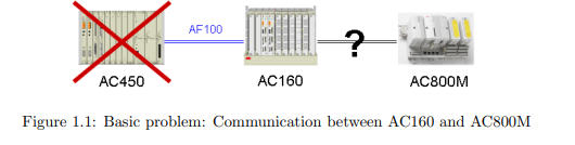
1.2 Problem Statement
Due to high investment costs, the technical management of power plants is a slowgoing business with long life-cycles. Thus, a considerable amount of hardware
devices currently in use are tens of years old. For future applications within ABB
Power Systems it will be necessary to connect a controller of the newest series used
within ABB, Control IT AC800M, with an older controller of the type Advant
Controller 160 (AC160). The problem is that these two controllers do not share
a fast communication interface of similar type and therefore cannot communicate
directly. The standard communication intended for AC160 is Advant Fieldbus 100
(AF100). However, AC800M can support a whole range of buses except for AF100.
As a consequence, the communication must be implemented using some relaying
technique.
1.2.1 The Use of OPC
It was decided in advance to realize the relaying connection using OPC. This solution was chosen because OPC is an open standard and very common in process and
automation industry. Furthermore, this solution offers a high potential to be used
for similar problems, since a lot of devices support this specification. However, OPC
is normally not used for fast controller-to-controller communication but for slower
visualization and logging purposes and there is no performance data available for
this kind of connection. The use of OPC is therefore both challenging as well as
interesting to gain more insights and know-how.
It is also to mention that a hardware solution addressing our problem is not
available yet. It is therefore necessary to have an alternative way using already
available parts, also for testing purposes.
1.3 Goals
The goals of this Master’s Thesis are stated as follows:
• Setup and evaluation of a test environment
• Setup of test systems
• Theoretical and practical evaluation of the test systems concerning performance, availability and reliability.
• Identification of improvements and different approaches
• Comparison with alternatives
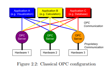
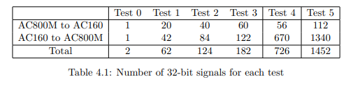
As a starting point for the performance requirements, the current implementation was taken. The corresponding quantity and type of variables are displayed in
Table 1.1 with 32-bit floating point values (floats) as analog in- and outputs and
1-bit boolean values as so-called status and command bits. In the current configuration with AC450 and AC160, all variables are written to the AF100 fieldbus with a
cycle time of 256 milliseconds. Therefore we determined the minimum requirement
for round-trip times from one controller to the other to exactly this time.
In agreement with the advisors, instead of elaborating the optional extension
stated in the task description (Appendix C), we spent more time on trying out a
second PROFIBUS approach and the theoretical derivation of a redundancy concept.
1.4 Structure
For the reader’s convenience this Master’s Thesis is structured thematically starting
with an overview of components and terms (2) in the next chapter. The following
chapters inform about the test system setup (3), the evaluations that were made
(4) and finally the results (5). In a subsequent chapter the subject redundancy
is treated (6) before the thesis comes to an end with the conclusion and outlook
(7). Additional information as well as a CD-ROM containing more detailed data is
located in the appendix of this thesis.
Chapter 2
Components and Terms
In this chapter, hardware and software parts as well as terms used for our test
system and evaluations will be described. Some additional devices and programs
concerning redundancy are introduced not until the chapter according. Information
on the version numbers can be found in Appendix B.
2.1 Basic Terms
• Performance, in this thesis, refers to the capability of a communication
component in means of speed and throughput.
• Availability is the term for the probability that a system will perform its
specified functions when used under stated conditions. A common mathematical definition of operational availability is Ao = MT BF/(MT BF + MDT),
whereas MTBF is the “mean time between failure” and MDT the “mean down
time” [2]. However, in this thesis, availability is used in a more general manner, since the basis for mathematical operations is not available.
• Reliability means the probability of a device remaining failure free during a
specified time interval, e.g. the maintenance interval: R = e
λt
• Redundancy is the implementation of extra components in addition to the
ones needed for normal operation. Thus, redundancy normally increases reliability and availability.
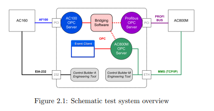
2.2 OPC
OPC, originally short for “OLE for Process Control”, is an open, standardized
software communication interface specification launched in 1996 by a task force of
different automation companies, later forming the OPC Foundation. As the former
name indicates, OPC is an adaption of Microsoft’s Object Linking and Embedding
OLE1
to the process control business, which used to be highly proprietary at that
point of time. Thus it was almost impossible to efficiently combine products of
different vendors. By providing so-called OPC servers with their devices, buses and
software, vendors open their products to any OPC compliant client able to connect
to the server for data exchange. Usually, an OPC server can handle several clients
at once, while these clients—e.g. visualization or calculation applications—can connect to different servers in order to obtain their needed information

Over the years, the OPC Foundation has been adding eight additional specifications to the original one, therefore the name OPC was freed from its original
meaning and is now used as an umbrella term [3]. Some important specifications
are quickly explained in the following:
• DA (Data Access) is the original and most widely used standard of OPC.
Its purpose is the cyclic polling of real time data, for example for visualization
purposes.
1
http://msdn.microsoft.com/archive/default.asp?url=/archive/en-us/dnarolegen/
html/msdn_aboutole.asp
• HDA (Historical Data Access), in contrary, specifies the access to already
stored data.
• AE (Alarms and Events) describes the non-cyclic, event-based exchange
of alarms and events.
• Data eXchange is a specification from 2002 which regulates the direct communication between two OPC servers.
For this Master’s Thesis it was made use both of the DA specification for the
main purpose of communication as well as the AE specification in order to display
and log round-trip times. Unfortunately, the promising Data eXchange specification
is almost inexistent in practice and could therefore not be used in our thesis.
The underlying technique to exchange data is the component object model
COM of Microsoft Windows, therefore OPC can only run on Windows operating
systems [4]. A new generation of OPC specifications recently published is called
OPC Unified Architecture (OPC UA) and is independent of COM, thus being able
to run on more operating systems as well as embedded devices [5].
2.2.1 OPC Data Access
OPC DA is organized in the hierarchical structure server, group and item. Items
correspond to variables and can be read and written. Furthermore, a quality and
time stamp is provided with each of them. When reading items, the value usually
comes from the OPC server’s cache, which is updated periodically with the values
of the device (or bus, component). However, it is usually possible to force a read
directly from the device. Clients organize their items in groups, which for example
share the same access method and update rate. Each OPC server has an unique
name, some vendors even offer the operation of multiple servers for the same device.
OPC DA provides different methods to access items, first of all synchronous and
asynchronous read and write operations. More important to us, there is also a
subscription mechanism, which is commonly used by modern clients in order to
reduce communication. That is, the client group subscribes to the server which
then “pushes” values towards the client only if they changed respectively exceed a
pre-defined dead-band. The client can force an update of all these values by issuing
a refresh call, which corresponds to an asynchronous read for all items of a group
[6].
2.3 Programmable Logic Controllers
This section informs about the two controllers involved and about the controller
that has to be replaced. Please notice that we use the term controller equivalent
to programmable logic controller (PLC) throughout our Master’s Thesis.
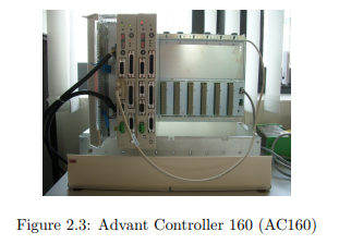
2.3.1 Advant Controller 160 (AC160)
The AC160 series was launched in 1997 to meet high speed requirements in turbine
control. To this day its outstanding performance is needed for fast closed loop
control (CLC). For our work, we were provided with a rack RF616 for the physical
mounting of the controller parts. The rack also delivers power to each device
and includes the BIOB Backplane Input/Output Bus which, among other tasks,
processes the communication between the processor module and the communication
interface. The tests in this Master’s Thesis were done with processor modules
of the type PM665 (containing a Motorola MPC8240 processor) and the AF100
communication interface CI631, both supporting redundancy [7]. To program the
processor module, its built-in EIA-232 interface was connected to the engineering
PC.
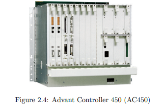
2.3.2 Advant Controller 450 (AC450)
AC450 is the controller to be replaced by the new generation. Its processor module
is built up around a Motorola 68040 microprocessor running at 25 MHz [8]. While its
performance is quite limited, AC450 also lacks of modern communication interfaces
and standards like Ethernet, which become more and more important.
2.3.3 Control IT AC800M
Control IT AC800M is the most current controller series used within all of ABB,
introduced in 2001 [9]. It strikes with its small outline and offers modern communication interfaces. For our tests we were provided with a processor module
PM864A which contains a Motorola MPC862 microprocessor running at 96 MHz
[10]. In addition to two EIA-232 interfaces, the processor module of AC800M offers
two built-in 10 Mbit/s standard Ethernet ports, used for instance to connect to the
engineering computer.
The communication interface CI854A is a sophisticated device to establish
PROFIBUS communication. The device even offers an own web interface which
allows e.g. the surveillance of the cycle time. The device is directly coupled to
the processor module via the Communication Extension Bus (CEX) [11]. At this
point of time, CI854A can only act as a PROFIBUS master, but not as slave. As
a consequence, communication partners must be slaves.
2.4 Bus and Network Communication
This section describes the different communication approaches used in our system.
2.4.1 Advant Fieldbus 100 (AF100)
AF100 is a high performance fieldbus system with time synchronization and the
most popular fieldbus used within ABB, common to almost all platforms. Although
the name Advant Fieldbus 100 is ABB proprietary, it complies to IEC standard
61375-3 as well as US-standard IEEE 1473 and is widely used in railways under
the name of MVB. AF100 works over twisted pair, coaxial and optical media at
a rate of 1.5 Mbit/s. For our system we made use of the first method only. Bus
master responsibility is shared by all communication interfaces with administrator
capabilities, that is, a bus master controls all communication for a certain time
interval and then passes on the bus master token. However, in our setup only AC160
were given administrator capabilities, even though the PCI-card would support
them as well.
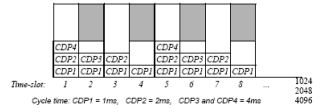
Figure 2.6: AF100 time-slot organization up to 2000 m bus length [12]
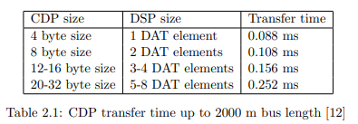
AF100 is a planned bus with a pre-determined scan table and thus meets realtime requirements. Process Data Transfer is managed through Cyclic Data Packets
(CDPs). Each CDP is configured individually on the communication interface for
a certain signal identity, cycle time, size and direction. Each broadcasted CDP has
a unique signal identity, whereas receiving CDPs can have the same signal identity,
provided they are situated in different communication interfaces. That is, multiple
interfaces can receive the same CDP. The cycle time determines how often the data
of the CDP is transferred on the bus. When a CDP is transferred on the Advant
Fieldbus 100, the interval between consecutive transfers is always the same, the
cycle time. Thus, process data transfer is deterministic, regardless of which other
tasks the communication interfaces perform.
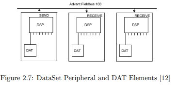
Figure 2.7: DataSet Peripheral and DAT Elements [12]
In AC160, one so-called DataSet Peripheral (DSP) can reference up to eight
32-bit values called Database Elements (DATs). Each DSP uses one CDP to be
transported on the AF100, and can therefore be configured for example with an
individual cycle time. In addition to cyclic message transfer, AF100 offers the
possibilities to send event-based messages using the Service Data Protocol (SDP).
This does not influence the cyclic data transfer at all. At a bus length up to 2000m
it is therefore necessary to keep the cyclic bus load under 70% in order to have
extra space for messages (depicted as gray fields in Figure 2.6) [12].
2.4.2 PROFIBUS DPV0
PROFIBUS (PROcess FIeld BUS) is one of the world’s most widely used fieldbuses and was launched in 1989 by a consortium of companies and institutions.
Until today it was continuously enhanced and extended [13]. It is available in three
variations:
• PROFIBUS-FMS (Field Message Specification) was the first PROFIBUS
communications protocol. It offers sophisticated functionality but is no longer
officially supported.
• PROFIBUS-DP (Decentralized Peripherals) has been designed for fast cyclic
data exchange at field level and is today often referred to DPV0. This specification was extended with DPV1 for acyclic and alarm communication and
DPV2 for slave-to-slave and isochronous communication as well as synchronized system time.
• PROFIBUS-PA (Process Automation) is used for the connection of devices
to a superior process control system. It supports intrinsic safe transmission
[14].
For this thesis, only the DPV0 protocol specification is relevant. Therefore,
when writing PROFIBUS, we are always referring to this specification. DPV0
allows the cyclic exchange of data from a master (initiator) to slaves and vice versa
at a high data rate up to 12 Mbit/s. Communication is organized in input and
output modules of defined size (e.g. one word or four bytes) for every slave, which
then are transmitted completely (non differential) once per cycle. The cycle time
depends on the number of bytes and slaves as well as on timeout settings. The
specified input and output data of one slave is limited to 244 byte each. While the
physical connection can also be established using fiber optics, we used the more
conventional EIA-485 electrical twisted pair connection.
PROFIBUS slaves come with a GSD-File (“Geraete-Stammdaten” in German)
which is an electronic device specification. Most PROFIBUS master systems allow
to directly import the GSD-Files of previously unknown slaves in order to include
them in the bus planning. That makes it easy and comfortable to build PROFIBUS
networks with slaves from different vendors.
2.4.3 MMS
The Manufacturing Message Specification MMS is an application level protocol developed during the eighties by General Motors. Its main goal was to unify communication to controllers independent of manufacturers. Other automobile, aerospace
and PLC companies adopted the protocol and since 1990 MMS is standardized in
ISO/IEC 9506 [15]. While being very general and open, MMS is reputed as heavy,
complicated and costly. Nevertheless MMS was an important step in development
and due to its independence of the underlying communication protocol it is still
being used today. Furthermore it worked as a reference model and has influenced
other protocols. Since 2002 the standard IEC 61850 for “Communication networks
and systems in substations” based on TCP/IP over Ethernet defines the mapping
onto MMS [16].
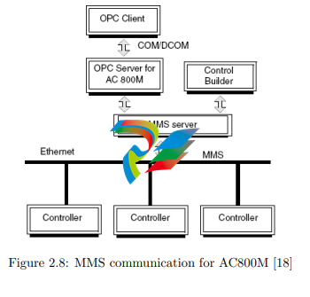
MMS is used as the main communication protocol for AC800M. On one hand,
this is the communication between controller and the superior control and engineering system, on the other hand the communication between several controllers
of this type as shown in Figure 2.8. One telegram can reach a size up to 1024 bytes
including the header, containing a maximum of 159 integers or 136 floats [17]
2.5 Personal Computer
For our tests we used a personal computer containing an Intel Pentium 4 processor
at a speed of 3.2 GHz and 2 GB memory running a Microsoft Windows Server 2003
R2 operating system
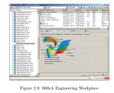
2.5.1 800xA and Development Environment
In order to setup, program and run ABB components, an Industrial IT 800xA
environment was installed on the personal computer. Besides a lot of additional
resources, this installation also encompasses the application development systems
for both controller types.
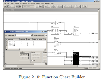
The development environment to program the AC160 was Control Builder A
(CBA) consisting of Application Builder, Function Chart Builder and Bus Configuration Builder. To program the AC800M controller, the engineering tool Control
Builder M was used.

2.5.2 AF100 Communication
To establish connection to the AF100 fieldbus, we inserted an ABB CI527 PCI card
into the personal computer. The according AC100 OPC Server, which allows us to
access the AF100 bus, was installed with the 800xA for AC100 software extension
[19]. It is to mention that AC100 OPC Server allows access on bit-level, for example,
an integer value is presented by the server both as integer value and split up in 32
boolean values.
2.5.3 MMS Communication
An Intel Ethernet PCI card allowed the communication with the AC800M via MMS
on TCP/IP. The according AC800M OPC Server is part of the 800xA installation.
All communication over this port is performed via the Manufacturing Message
Specification (MMS) protocol running over TCP/IP, utilized for example by the
engineering tool to program the controller. The same connection can also be used
for controller to controller communication when having several MSS-ready devices.
Furthermore, the AC800M OPC Server communicates with the controller via the
same protocol and infrastructure, making available all variables by default [17].
2.5.4 Beckhoff PROFIBUS Communication
For the first PROFIBUS connection we used the FC3102 PCI card from Beckhoff.
This card was chosen due to its flexibility: It provides two ports in one PCI card
which can be freely adjusted either as master, slave or passive bus monitor [20].
We ran Beckhoff’s TwinCat software: TwinCat System Manager to configure
the card, TwinCat IO as driver and TwinCat OPC Server. Beckhoff inserts an
abstraction layer on top of TwinCat IO which operates with the ADS (Automation
Device Specification) protocol [21].

2.5.5 Woodhead PROFIBUS Communication
The Woodhead Electronics SST-PBMS-PCI card is the only card to be found that
provides multi-slave functionality. That is, even though the card only has one physical SUB-D9 interface, it can emulate up to 125 PROFIBUS slave interfaces [22].
This allows not only the simulation of large PROFIBUS outlines in one PC, but—
and more important to us—also makes it easy to bypass the 244 byte limitation
specified by PROFIBUS DP

Figure 2.13: Woodhead Electronic SST-PBMS-PCI card
We configured the card with its configuration tool SST Profibus Configuration.
Furthermore we used the according OPC Server for PBMS Card which was configured with Multi Slave OPC Configuration Utility
2.5.6 OPC Bridging Software
The programs we used to interconnect two OPC servers were Matrikon’s OPC
Data Manager (ODM) [23] and Kepware’s LinkMaster [24]. These programs called
OPC routers or OPC bridges are able to read data from one server and write
it to another. Both programs are similar in configuration and operation. The
functionality includes the definition of groups and update rates, input/output pairs,
dead-bands and quality checks. LinkMaster even allows to write one input value to
more than one output variables and to perform mathematical operations in between.
To make bulk configuration easier (e.g. with Excel), both programs allow to import
and export the configuration from and to comma separated values (CSV) files.
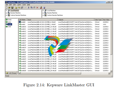
Figure 2.14: Kepware LinkMaster GUI
We ran both bridging programs with a fully functional, time-limited testing
license provided for free by its vendors for the duration of our thesis.
2.5.7 Helper Programs
For setup and testing, a range of other software was used on the engineering/test
system computer. The most important programs are shortly specified here:
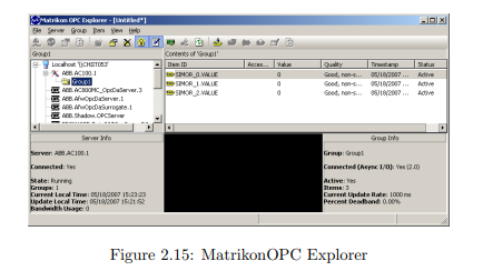
• MatrikonOPC Explorer is a freeware OPC client allowing to connect to
any compliant OPC server and displaying the value of chosen tags. It also
supports writing of variables and preserving settings. Furthermore, it allows
measuring the maximum update rate of the OPC servers it is connected to.
• Office 2003 of Microsoft was used for day to day work and configuration
tasks. Especially Excel was helpful for variable definition in AC800M and for
bulk configuring the bridging software using CSV files. Furthermore, with the
Bulk Data Manager plugin, Excel allows convenient bulk setup of PROFIBUS
devices and its variables.
• Process Explorer of Microsoft’s Sysinternals is a freeware program to monitor system processes and their use of resources.
• Synergy was used to operate two computers and screens with only one keyboard and mouse.
• Irfanview helped with the caption of screenshots.
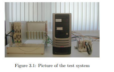
Chapter 3
Test System
This chapter describes the test system we used for our evaluations.
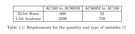
3.1 Overview
The main goal is to connect a controller of the type AC160 with a controller of
the type AC800M which do not share a common communication interface. As
this happens using OPC, the intermediate relay is implemented using a Windows
computer. While there is only one possibility to connect AC160, we tried out
different approaches for linking AC800M.
3.2 AC160 Side
The AC160 is attached to the personal computer via the CI631 using the Advant
Fieldbus 100 and a PCI card CI527. Due to limited communication facilities, this
is the only reasonable choice for this task. Since both communication interfaces
inherently support line redundancy (see Chapter 6), two media were used for this

connection. To program the processor module either a separate EIA-232 connection
or the AF100 fieldbus itself was used. The according AC100 OPC Server is part of
the 800xA for AC100 extension but can also be installed stand-alone [25].
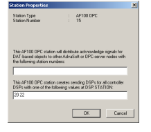
All DSPs sent from AC160 are available in the AC100 OPC Server if not set
to be filtered out by the configuration tool. It is also possible by default to write
to these variables, however, if not configured otherwise the values written on the
OPC Server are not sent using planned DSPs but using event-based Service Data
Protocol (SDP) messages. As a consequence, all communication towards AC160
becomes very slow and is not even guaranteed to arrive. It is therefore necessary to
implement receiving DSPs in the AC160 and to configure the AC100 OPC Server
to send DSPs. The latter is done using the Bus Configuration Builder [26]. In the
properties dialog of the OPC station it is possible to specify the DSPs that have to
be sent [27]. Using this method, data transmission towards the AC160 becomes as
fast as reading from it
AC800M Side
For all of our evaluations we connected the AC800M with our personal computer
using Ethernet. This is firstly necessary for programming and managing the controller. Secondly, we displayed the measured results using OPC AE and therefore
needed this connection in order to let the AC800M OPC Server communicate with
the controller. Last but not least we tested this connection for our purposes as
described in the following subsection.
3.3.1 Communication via MMS
MMS using TCP/IP over Ethernet is the standard communication between computer and controller, and since with AC800M OPC Server a ready-to-use connection
is provided, we included this approach in our evaluations. However, the performance
of this connection depends directly on the CPU load of the AC800M as well as on
the Ethernet network traffic [28].
3.3.2 Communication via PROFIBUS
Due to the missing real-time behavior of a standard Ethernet link, it was planned
right from scratch to test this approach against a PROFIBUS connection. With the
CI854A, a sophisticated PROFIBUS communication interface for AC800M exists,
supporting 12 Mbit/s baud rate not depending on the CPU of the processor module.
This reasons and the fact that it enjoys a high acceptance in entire Europe made
PROFIBUS to our first choice of all fieldbus systems. Another promising bus,
FOUNDATION FIELDBUS High Speed Ethernet (FF HSE) was dismissed after
having recognized that the according communication interface CI860 has a very
poor throughput of only 500 32-bit values per second [17].
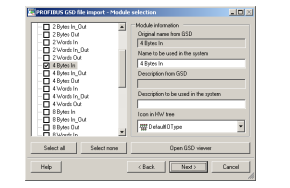
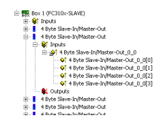
Figure 3.4: Module selection in Device Import Wizard
A typical use of PROFIBUS is to connect several slave devices such as sensors
with one or few masters (for example a controller) on one single bus (up to 126
devices). Often the amount of data per slave is very small, since it only represents
an input/output state or a measured value. Therefore it is rather exotic to use
PROFIBUS as a point-to-point communication with a big amount of data as we
did in our case. Since the first test showed that the Beckhoff PROFIBUS solution
has performance problems, it was decided to test a second PCI card/OPC server
product from Woodhead Electronics. Both PROFIBUS cards were configured in a
way that one module consists of four 8-bit bytes to transport integers or two 16-bit
words to transport floats. These mappings were realized using the Device Import
Wizard in CBM and the PCI card’s configuration tools [29].
3.4 Bridging Software
A core part of our system is the OPC bridging software establishing the connection
between two OPC servers. Two different products were tested: OPC Data Manager
from Matrikon and LinkMaster from Kepware. Both products were evaluated due
to their specifications, bulk configuration possibilities (CSV files import/export)
and availability for testing.
There are different possibilities for connections in OPC Data Access. The standard method implemented in both programs is subscription, that is, the bridging
software subscribes as a client to the the source OPC server A to read from. The
source server then pushes changing values to the client at a fixed speed (10 milliseconds is the maximum for LinkMaster, 1 ms for ODM) which writes them to
the destination server. As a consequence, the load and therefore the performance
of the bridging software depends on the number of changes.
Since OPC DA is organized in subscription groups, the signal pairs in the bridging software were combined in groups of 10 to 32 signals with identical update rates
of 10 milliseconds. Both programs also support the (faster) processing of arrays instead of single values. However, we could not take advantage of this solution since
the OPC servers do not support arrays.

3.5 Resulting Test Systems
This section shows more detailed models of the resulting three test system setups
following the considerations above. The AC160 side (illustrated on the left hand
side) stays the same for all three setups. The models visualize one main challenge
of our task, namely the big quantity of different interfaces and each component
running with an own unsynchronized cycle time. While the models are not complete, they include all parts that are considered relevant in relation to our time
domain milliseconds. It is to be mentioned that the impact of BIOB and CEX on
the performance is considered to be very small compared to the other parts.
3.5.1 System 1: Beckhoff PROFIBUS
Figure 3.7 shows the schematic setup for the Beckhoff PROFIBUS approach. It
is to mention that Beckhoff uses their proprietary ADS protocol to communicate
between the OPC server and the card driver, which was therefore outlined in this
figure [20]. The maximum update rate of TwinCat OPC Server is 2 milliseconds,
the cycle time of the variable i/o task is 1 ms.
Figure 3.7: Schematic setup of Beckhoff PROFIBUS approach
3.5.2 System 2: MMS
The MMS approach is depicted in Figure 3.8. In contrary to the PROFIBUS
solution there is no need for an additional communication device connected to
CEX bus as the Ethernet port is located in the processor module itself, using its
resources. Unfortunately, the maximum update rate of the AC800M OPC Server
is limited to 50 milliseconds, which is a comparatively high value compared to the
cycle time of other system parts.

3.5.3 System 3: Woodhead PROFIBUS
In contrary to Beckhoff’s solution, Woodhead implements a more direct access path
for the OPC server. Its maximum update rate is 1 millisecond. The GSD-file of
the SST-PBMS-PCI card had to be slightly modified in order to be importable by
Control Builder M. Furthermore, there exists a trick how to simplify bulk setup of
OPC tag names. More information on the latter as well as a working GSD-file is
enclosed with the CD-ROM in the appendix.

Chapter 4
Evaluation
In this chapter we describe the evaluations performed on the test system. In order
to implement the different tests, we needed to program both controllers with appropriate code, which presumed the know-how for two quite different application
development systems and engineering tools (see [30], [31], [32] and [33]).
4.1 Test Systems
As described in the preceding chapter, we evaluated three different test system
variants. While the AC160 side physically stayed the same for all tests, the AC800
connection was tested with the following approaches:
• PROFIBUS connection with Beckhoff’s card and server
• Standard MMS connection using an Ethernet card
• PROFIBUS connection with Woodhead’s card and server
Due to reasons explained in the next chapter, all main tests were performed with
Kepware’s LinkMaster OPC bridging software.
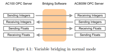
4.2 Basic Idea
The basic idea behind all tests is the definition of a complementary set of receiving
and sending variables to each of the two controllers. During each controller program
cycle all receiving variables are read from the bus/network and all sending variables
are written. On the other side of the bus/network, the OPC server makes the
variables available. The OPC bridging software, acting as an OPC client to the
servers, links the two corresponding variables by reading the values from one server
and writing them to the other.
4.2.1 Short Circuit
To explore the behavior of one side or to isolate problems, we also performed test
with a “short circuit” configuration. That is, the bridging software is not configured
to link the variables from one OPC server to the other, but right back to other
variables on the same server.

4.3 Variables
This section informs about the type and quantity of variables used to test the
connection.
4.3.1 Data Types
According to the requirements, only 32-bit floating point and boolean values have
to be processed. Since the booleans are packed into integer values, the problem
modifies to the transport of 32-bit floating point and 32-bit integer values.
4.3.2 Packaging of Booleans
The are various reasons to pack booleans into integer values instead of processing
them one by one:
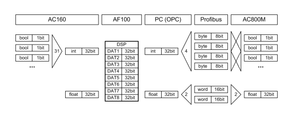
Figure 4.3: Data types in different sections with PROFIBUS
• The smallest possible PROFIBUS module size provided by both cards is one
byte. If processing booleans one by one, 7 bit would get “lost” for every value,
which reduces performance.
• In MMS telegrams, one single boolean requires 3 bytes space whereas one
integer containing up to 32 booleans uses only 6 bytes [17].
• A smaller number of variables improves the performance of the OPC connections.
• One can save a lot of configuration effort for the bridging software.
• AC800M supports transparent packaging of the booleans into PROFIBUS
modules, that is, it is not even necessary to manually pack them into integers.
• AC160 offers a program code element to pack/unpack booleans into/from
integers.
Since the size of one variable in an AF100 DSP is limited to 32 bit, we intended to
pack this amount of booleans into an integer value. However, the packaging program
code element offered in AC160 treats the last bit as a sign flag not compatible to the
transparent mapping of the AC800M. Instead of implementing additional program
code we therefore decided to set this last bit aside and pack only 31 bits into one
integer value.
4.3.3 Quantity
In order to learn more about the behavior of the concerned parts, we performed six
main tests with different amounts of variables:
• The first four Tests 0 to 3 are intended to get an overview on the behavior
of the configurations. They are designed such that they can run with all test
system variations, that is, the amount of data does not exceed 488 bytes in
one direction (due to the limitation of two PROFIBUS slaves with Beckhoff’s
solution). Test 0 is carried out with only one integer value going forth and
back. Test 2 contains twice and Test 3 about three times the quantity of
variables as in Test 1, allowing to observe linear tendencies.
• Test 4 represents the real requirements for the quantity of variables and data
types according to Table 1.1. Thus, the results of Test 4 are the most important ones for statements regarding the feasibility of the setup. In contrary
to Tests 1 to 3, the amount of floating point values transmitted from AC160
to AC800M is much higher. As a consequence, it cannot be performed with
Beckhoff’s PROFIBUS solution.
• Test 5 is the duplication of Test 4, trying to determine the limits of the system.
4.4 Measurements
The following methods were used to evaluate our test system.
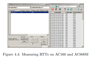
4.4.1 Round-Trip Time
The most relevant evaluation we performed is the round trip time (RTT) measurement. For this reason, a boolean value (packed in an integer) is set true and
sent from the AC800M controller to the AC160. At the same time, a stopwatch is
started. Inside the AC160 the value is moved to another boolean and sent back.
As soon as this value returns to AC800M, the stopwatch is stopped and the RTT
displayed via generated event that allows subsequent interpretation for 500 entries.
This number is the minimum sample quantity for our results discussed in the next
chapter. The actual communication slowed down by the cycle time of AC160 and
the resolution of the results is limited by the cycle time of AC800M. The results
can therefore be looked at as worst-case values, while the exact time used for communication only is considered to be somewhat lower in most cases.
An important thing to know is that all the other values, which are transmitted
with every cycle but are not directly relevant for measuring the RTT, changed every
controller cycle. While this does not matter for the fieldbus communication it has
an influence on the OPC communication. The common subscription mode for the
OPC bridging software works differential, that is, values are only transmitted when
they change, which saves CPU load. In order to test the worst case scenario—which
is our task—it is therefore necessary to transmit a new value with every cycle.
A problem that showed up was the cycle time of the AC160 program code
and the cycle time of DSPs transmitted on AF100. For Tests 0 to 3, both values
are constantly 8 milliseconds, which make these tests very comparable. Since the
amount of values increases a lot for Tests 4 and 5, the performance of both the CPU
and the bus are not sufficient anymore and need higher cycle times. However, higher
cycle times on AC160 and AF100 make the RTT slower and results are not directly
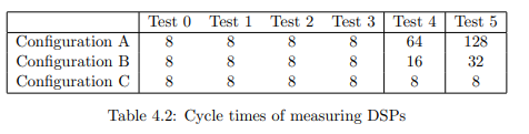
comparable to the first tests due to changed conditions. For better understanding it
was therefore decided to test with different configurations and cycle times depicted
in Table 4.2. The trade off is to have lower (faster) cycle times in exchange for OPC
server load: While with configuration A it is a worst-case test, the RTTs get very
high and are not directly comparable anymore. Configuration C makes also Test 4
and 5 directly comparable to the others, but it is not a worst-case test anymore.
For better understanding the following definitions we introduce two terms: For
each configuration there is only one receiving and one sending DSP relevant for
measuring the round-trip times on AF100, containing the variables to time the
connection. We call them the two measuring DSPs while all other DSPs are called
load DSPs.
• Configuration A: The cycle time for all DSPs on AF100 is identical and
complies with a safe choice for the AF100 bus load (see Appendix D). Since
for Tests 4 and 5 the program code runs faster than the bus, there is a new
value sent in each bus cycle.
• Configuration B: The cycle time for the measuring DSPs is set to same value
as the program code cycle time. All load DSPs are sent as in configuration A.
For Tests 4 and 5 this means that load values change only every fourth time
in comparison with the measuring value.
• Configuration C: It is of course not possible to set the DSP cycle time faster
than the program code. Thus it would never be possible to reduce it to 8 ms
for Tests 4 and 5. We therefore installed a second processor module, working
at 8 ms cycle time and only processing the measuring DSPs while the load
DSPs were still processed in the first module. For Tests 4 this means that
load values change only every eighth time compared to the measuring value,
for Test 5 it is even only every 16th time.
The 8 ms cycle time for AC160 program code and AF100 for Tests 0 to 3 was
chosen since it fits for all these tests and still is in the range of other component’s
cycle times. Of course it would have been possible to simply increase the cycle
times for Tests 0 to 3 in order to have the same preconditions as in Tests 4 or 5.
But since it is our task to evaluate the performance of the communication and not
the controller we decided not to falsify results by doing so.
4.4.2 Integrity
The intention of this measurement is to prove that every linked value is communicated correctly (not just the ones relevant for measuring the RTT). For this reason,
all float variables were set to exactly the same value, being increased by one at
every cycle and sent from one controller to the other. On this receiver side, the
range between the maximum and minimum value are identified. If the range is
small, integrity is good. If the range is wide, this shows that some variables do not
change at the same time and therefore are not transmitted correctly.
4.4.3 Availability
To get an idea about the availability of such a system, one configuration was running for one week (seven times 24 hours). The goal of this evaluation was to find
out about the capability to run the system for a longer period or if it fails after some
hours. Furthermore, the two preceding measurements are included with recording
the average and maximum RTT as well as average and maximum integrity check
range. Due to time limitation this availability long-time test was only performed
using the Woodhead PROFIBUS approach and a realistic variable quantity according to Test 4 Configuration B. In order not to impair the measurement and falsify
results, we abandoned a more detailed logging.
While numerical information on availability of industrial devices it based upon
extensive tests and long-time information, this was not within the scope of our
thesis. A mathematical approach cannot be performed either, due to the lack of
numerical information of the single parts in the personal computer.
Chapter 5
Results
In this chapter we will present and discuss the results gained from our evalutations.
5.1 Bridging Software
We started the evaluation using Matrikon’s OPC Data Manager. Unfortunately,
the behavior of the GUI was sometimes unsatisfying, particularly due to its long
delays. Additionally, the communication stopped at times for unknown reasons.
The equivalent product LinkMaster from Kepware offers similar possibilities in
configuration but did not show these effects. Furthermore, the performance of
LinkMaster could be determined as being vastly better than the one of ODM:
For Test 3 with Beckhoff PROFIBUS the median RTT with LinkMaster is 510
milliseconds, whereas with ODM and the same preconditions the RTT becomes
more than ten times slower. As a consequence, all main tests were performed
using Kepware’s LinkMaster software. For some configurations we enabled a device
refresh rate of 10 ms for only one group in each direction, which prevented the
program from unwanted stopping.
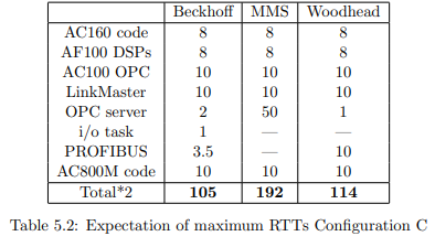
5.2 Round-Trip Times
This section shows the results for the round-trip time tests, grouped by test system variations. In Table 5.2 we show the expected maximum RTTs based on the
addition of cycle times and update rates.
Test 1 Test 2 Test 3 Test 4 Test 5
2.7 ms 3.2 ms 3.5 ms 7 ms 10 ms
Table 5.1: Rounded PROFIBUS cycle time measurements
For the PROFIBUS cycle times we entered the maximum values measured with
CI854A shown in Table 5.1, Test 3 for the Beckhoff setup and Test 5 for Woodhead
approach. The configuration of the PROFIBUS parameters was done automatically
by AC800M with “actual value based” method for all test we performed.
5.2.1 System 1: Beckhoff PROFIBUS
Evaluations were performed for different amounts of signals as defined in Table 4.1.
Starting with the Beckhoff PROFIBUS solution, we could observe that the RTT
increases linearly to the amount of signals. While test results with one single signal
(Test 0) were promising, the following tests were already unacceptable, although
defining only a fraction of the required amount of variables.
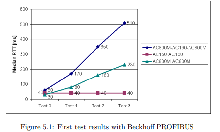
After short-circuiting the connections it was quickly determined that the bottleneck is to be found in the writing to the AC800M. After inspecting the LinkMaster
software and PROFIBUS configuration the bottleneck was isolated as the OPC
server to PCI card communication. Interrogating Beckhoff support confirmed this
suspicion: Since it is much more common to read from OPC servers, the reading
process was optimized by transporting several values in block mode from the PCI
card to the OPC server, using Beckhoff’s own ADS protocol. In contrary, values
written to the OPC server are transmitted one by one [34]. This explains our results, and after putting into operation two more clone OPC servers, which is the
maximum number, the RTT expectedly was more or less three times lower. However, with 190 ms median RTT for Test 3 and added configuration effort, this is
still not satisfactory. It is to add that Beckhoff offers a nice and sophisticated configuration tool, which also allows the swapping of words and bytes. This function
is used when processing float values which are interpreted different in FC3102 PCI
card than in CI854A.
After these findings it was inevitable to look for another solution, also keeping
thoughts in mind that it would be necessary—due to the 244 byte limitation—to
put six FC3102 PCI cards into a computer in order to have enough capacity for
all required values, or alternatively to have eleven DP/DP-couplers at work1
. The
idea to “multiplex” data over the PROFIBUS in order to defuse byte limitation was
discarded as impracticable.
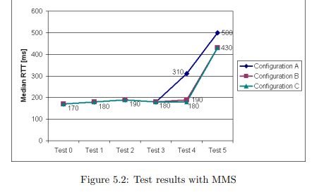
5.2.2 System 2: MMS
Before looking at the results, it is to mention that, compared with the PROFIBUS
solution, the MMS approach suffers from vast disadvantages: Firstly, the maximum
update rate of the AC800M OPC Server amounts to 50 ms and is therefore a big
obstacle. Since MMS cannot perform much better anyway (we estimate around
40 transactions per second [28]) this rate is justified, though. Secondly, the performance depends on the processor module CPU and network traffic. While the
1DP/DP-couplers are hardware relaying devices able to connect two PROFIBUS DP masters,
acting as a slave device on each side and copying data back and forth.
median RTTs with Configurations B and C meet our requirements, the results could
not convince us entirely. As suspected, the standard deviation of the measurements
is enormous. For different configurations of Test 4 it varied in the range from 40.9
to 62.7 ms.
It is not due to MMS that the results for Test 5 show such bad results. This
time it is the fault of our personal computer which is not able to handle this amount
of variables anymore. That is, the CPU load reaches 100% and therefore slowing
down the LinkMaster process.
5.2.3 System 3: Woodhead PROFIBUS
Since the SST-PBMS-PCI card supports the definition of several virtual slaves in
one card, the 244 byte limitation is not a problem any more. Thus, also Tests 4
and 5 could be performed with this one single card. This card and its server show
a good performance in both directions even with a big quantity of variables. Of
course, the CPU overload problem with Test 5 shows up here as well.

While the performance is satisfactory, another problem could not be solved well:
The word order in CI854A is interpreted differently than in the SST-PBMS-PCI
card. More precisely, 32-bit floats are split in two 16-bit words on PROFIBUS
and are thus sent in a certain order (see Figure 4.3). They are re-assembled in
the opposite interface just the other way round, such that floating point values
are always interpreted wrong. According to Woodhead Electronics and ABB, this
alleged small problem cannot be solved changing the configuration of either part.
At the present day it is therefore necessary to implement additional program code
in AC800M to manually perform word swaps for each float. It is to add that we experienced the configuration tools offered by Woodhead as being of less convenience
compared with Beckhoff’s solution. Especially the naming of tags in big quantities
is troublesome, but fortunately there could be found some workarounds [35].
5.3 Integrity
The results of our integrity test for selected configurations are very satisfying. The
maximum range of the received variables never exceeded the value to be expected
according to the maximum RTT. As an example, for Test 4 Configuration B a
maximum range of 6 in one direction is considered a normal delay due to transmission time and not indicating an integrity problem of the bridging software or
different parts. More detailed, since we measured a minimum RTT of 60 ms and a
maximum RTT of 290 ms for this specific setup (results contained on CD-ROM),
the difference of the fastest possible way and the worst path in one direction is
considered about (290ms − 60ms)/2 = 115ms. Within this time-frame, the program code (cycle time 16 ms) is executed 7.2 times. That is, if two variables arrive
at the same time, but one took the fastest and one the slowest path, a maximum
difference of 7 is to be expected. However, while the integrity check showed that
things run correctly for different variants and configurations in a short-term view,
its results of the long-time test covered by the next section might even be of more
importance.
5.4 Availability
The long-time test lasted for exactly one week and ran without interruption, therefore proving the basic long-term functionality of the system. Within this time, a
quantity of 2,283,900 samples was taken and analyzed.
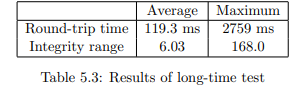
The contents of Table 5.3 show that the results are satisfactory in average. With
an expected maximum RTT of 146 ms according Configuration B2
, the average
RTT value is inside the expected range. The average integrity range fits to this
value and affirms the correct transfer of values also in a long term. However, the
maximum RTT of almost three seconds and the consequential integrity range is
not what we had expected from our system. Most likely this maximum RTT are
due to temporary CPU overloads caused by concurrent processes on the personal
computer, or because of an OPC server failure. If an OPC server fails, LinkMaster
tries to restart it after some time, however, this time was adjusted to 10 seconds
for our evaluations.
In contrary to the RTT test above, all floating point signals in AC800M had to
be processed one by one in order to switch the word order. This was necessary for
the integrity evaluation, otherwise the signals would have been interpreted wrong,
2Replacing the first two values with 16 ms in Table 5.2
causing a worthless range. This extra program code slowed down the cycle time
such that it was not possible anymore to keep 10 ms, which of course also influences
the RTT results. With an average cycle time of 12 ms, the impact is still not
devastating, though. A maximum cycle time of 43 ms was displayed at the end of
the test.
5.5 Summary
Figure 5.4 shows the combined results for the different variants. For better comparability, only Configuration C is displayed, such that the relevant DSP cycle time
is 8 milliseconds for all tests (see Table 4.2). It shows clearly, that the test system variation with Woodhead PROFIBUS returns the best round-trip times, while
the Beckhoff approach is worthless for our task. Moreover, its ability of emulating several slaves saves the effort of inserting multiple PCI cards. Beside all these
advantages, the Woodhead PROFIBUS approach causes the word swap problem,
which cannot be solved without adding program code at this time.
Whereas MMS also meets our requirements, it is about two times slower than the
Woodhead approach. Furthermore, the standard deviation of the RTTs measured
is vastly greater with MMS than with PROFIBUS. This is remarkable, since our
test were made with a direct Ethernet link (crossed cable). As the performance
of MMS depends on network traffic and AC800M’s CPU load, it is to be expected
that communication using MMS will get slower and even less deterministic in a real
environment

Although on the first spot Test 5 seems to be useless, this is not the case at
all. Firstly, it proved that the system basically works even with this amount of
variables. Secondly, while Test 4 is the most relevant evaluation concerning the
real requirements, Test 5 was intended to look for the limits of the current system,
Chapter 6
Redundancy
This chapter will provide theoretical considerations on redundancy. Since the
Woodhead PROFIBUS solution was the most promising approach, our considerations are based on this test system variation and the amount of signals according
to Test 4, which resembles the real requirements.
6.1 Terms and Concepts
Please notice that when talking about redundant components in this context, we
mean duplication if not stated otherwise. The term redundancy does not define the
number of redundant components in general.
6.1.1 Levels of Redundancy
There is a large variety within the levels of redundancy. While it is possible to
double only the most important or critical components, one can also make a whole
system redundant. This usually allows the concurrent outage of several different
parts of a system (e.g. a processor module and a bus line) without interrupting
the whole system. An outage can be an unplanned failure of a component but also
a planned maintenance action. Security relevant parts like protection systems are
often even implemented three times or more.
It is also important to know that redundancy can be implemented on different
levels in communication. Most redundancy hardware devices or software programs
that are able to switch between different connections work on a protocol level,
that is, they recognize errors in the communication protocol e.g. if a device fails
or the connection is broken. They are not able to identify errors in the transported data, though. In contrary, redundancy logic on application level checks the
values/contents of the transported data, and therefore also detects errors if the protocol itself runs correctly. It is also possible to combine these approaches, e.g. if an
application level program is able to force a switchover in a physical switch. A typical specification for the maximum switchover time in the turbine control business
is 20 ms.
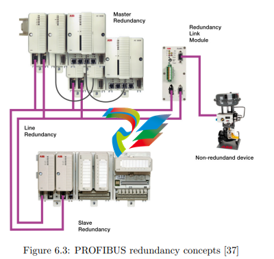
6.1.2 Master-, Slave- and Line-Redundancy
In bus systems there are three aspects of redundancy which can be combined arbitrarily. Since the outage of a non-redundant bus master in a classical master/slave
bus system like PROFIBUS interrupts any communication, it is very common to
implement bus master redundancy. In contrary, slave redundancy can be implemented depending on the importance of a specific slave. For real master or slave
redundancy it is of course necessary to implement two completely independent
communication stacks [36]. In practice this is normally done by using two identical
communication interfaces. The two interfaces communicate directly or via a third
component (e.g. the processor module) to be activated or deactivated and exchange
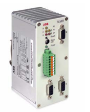
configuration data. Line redundancy means the multiple presences of physical media. A redundant master/slave bus system is showed in Figure 6.3. ABB offers a
device called RLM01 to connect single-line PROFIBUS slaves to a line redundant
layout, allowing reducing the non-redundant part to a short distance. Since the
device needs to copy data, it causes a delay, but this is very small compared to our
cycle times (about 1.5 µs at 12 Mbit/s).
6.1.3 Transparency
For the different components of a redundant system it makes a difference whether
the redundant pairs behave in a transparent manner or not. If they behave transparently, the other parts recognize a redundant pair as one single device and will
not have to do anything; at the most there will be a more or less drastic pause due
to the switchover. If redundant components behave not transparently, it is usually needed that nearby components are intelligent enough to check which device is
working correctly.
For redundant components which behave transparently it is inevitable to have
a redundancy communication (RedCom), which can be a direct link or be managed
by a superior component. This connection is on one hand needed to determine
which component is the active one and which is in stand-by mode. On the other
hand, also status information has to be communicated. If a component fails it can
for example be very important that the redundant part is able to recover the most
recent values in order to take over the communication.
6.1.4 Stand-by modes
There are different modes of redundancy. Sometimes, the redundant parts run in
parallel (load balancing) but can take the whole load in case the second system
stops working, as for example with water pumps or internet web servers. This kind
of redundancy is sometimes also referred to as hot standby with load balancing.
With line redundant bus systems, the sending component usually writes on both
lines whereas the receiving part chooses the line to read from.
In contrary there exist modes where only one part of a redundant pair can be
active, while the other part is in a standby mode ready to take over. Dependent
on the level of stand-by we talk about cold, warm or hot stand-by. Cold stand-by
usually means that the redundant system first has to start up and gather necessary
information before it is able to take over the communication, causing a comparatively long delay. Hot stand-by in contrary means that the redundant part is all
the time up and running and even knows status information of the active system,
always ready to take over the shortest possible amount of time. Warm stand-by at
last is something in between.
In bus systems, where normally the different bus subscribers are addressed, the
“flying redundancy” concept as in the CI854A can be used. That is, the active
communication interface and the backup interface always have the same address,
independent of which is the active one and which the backup. As a consequence, the
active and the passive interface have to switch addresses if a switchover takes place.
The advantage of this implementation is, that the backup slave has a valid address
and therefore can be reached as well, to receive status information, for example.
Moreover, such a switchover is transparent for the other bus subscribers. However, if there is an error during the switchover, it can happen that both redundant
components have the same address, the effects of which would be devastating.
6.1.5 Power Supply Redundancy
A lot of controllers and automation components are prepared to be connected to
two different power sources to further avoid outages. Establishing redundant power
supply, however, is a topic on its own and not covered by this Master’s Thesis.
6.2 Considerations
In this section we will make considerations on redundancy for the different parts
of our test system. Please notice that we omit a solution using only one personal
computer, since, in our opinion, this is the weakest part of our system, and numerous
software parts (e.g. the bridging programs) cannot be installed/run twice in order
to increase availability. We therefore aim at two PCs right away.
6.2.1 AC160 Side Devices
The AC160 controller and AF100 fieldbus provide a sophisticated redundancy concept. Thus, it is very common to insert two redundant processor modules as well
as two communication interfaces into one rack. For other bus participants this
configuration works transparently, so they do not care which PM/CI combination
is currently in use and which is in stand-by mode. All communication interfaces
already support line redundancy with two ports, this is also true for the CI527 PCI
cards.
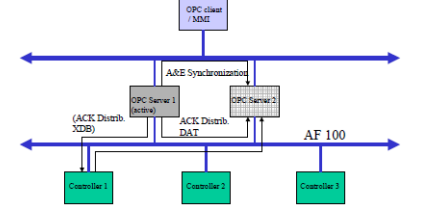
Not only controllers are included in the redundancy concept, but also OPC
servers. That is, if two personal computers with CI527 and AC100 OPC Servers
are connected to the same AF100 bus, both servers can provide data sent from the
controller. Unfortunately, the redundancy concept is limited as this will not work in
the opposite direction when using DSPs, which are vital for our application: Only
one of the two servers is allowed writing to a specific variable on the controller.
However, since we need to transmit a lot more values from AC160 to AC800M than
vice versa, the OPC server redundancy concept helps us a great deal anyway: We
do not have to define and send all these values twice (it is to mention here that
defining and sending variables in AC160 is considerably less comfortable than in
AC800M).
In contrary, if we want redundancy for receiving variables, we have to define the
receiving DSPs twice. The according redundancy brainpower must then be placed
in the controller program code itself, that is, the code has to compare each received
data pair and then decide how to proceed. In other words, the redundancy of the
OPC servers/PCI cards is not transparent from the view of the AC160. Achieving
this transparency would only be possible by modifying the OPC server to support
transparent redundancy when writing DSPs to the controller, or by the development
and insertion of a specific hardware device between the AC160 and the PC.
6.2.2 AC800M Side Devices
Similar to the AC160, the AC800M supports processor module and communication
interface redundancy for PROFIBUS as shown in Figure 6.3. In order to increase
the availability of the CEX bus, also the redundancy link module BC810 is inserted
[10].
In contrary, the Woodhead PROFIBUS card and OPC server does not support slave redundancy and therefore limits the concept. It is to add, that no
single PCI card/OPC server combination product that supports slave redundancy
could be found on the market. However, Woodhead offers an API to control their
PROFIBUS multi-slave card. That is, it would be possible to program an own
redundancy logic for the PCI card. The OPC server, which has to support redundancy as well, needs to be adjusted or reprogrammed. Implementing this redundancy brainpower in the personal computer, one of the two cards has to be
the active card while the other is in standby mode to appear transparently to the
AC800M bus master.
Since the SST-PBMS-PCI card neither does support line redundancy, we would
have to insert two cards in one computer and implement the line redundancy logic
as computer software. As a far less laborious alternative, the RLM01 introduced
earlier can be inserted.
The automation company Comsoft offers a hardware device called PRS to implement master redundancy in PROFIBUS DP systems [38]. It is intended to connect
two masters with the same address to one PROFIBUS. If one master fails, the device, which contains a galvanic switch, changes to the other master. The switchover
can also be initiated from outside via PROFIBUS itself or an additional Ethernet
connection. The device is intended for implementing master redundancy, which
is already done in our case. But, according to Comsoft, it is possible to “misuse”
the device for implementing slave redundancy and therefore replacing a software
solution [39]. However, logic to force a switchover would be needed anyway in order
for the system to work properly
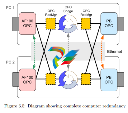
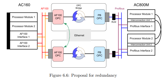
6.2.3 OPC Communication
It is of course necessary that the OPC servers for both bus interface cards are running, as well as the bridging software, e.g. Kepware LinkMaster. In addition it
would be possible to add specific redundancy management software on the computers and interconnect them via (redundant) network and DCOM to the servers
located on the second computer. That would theoretically allow the setup of a completely redundant system, coping with the outage of two different OPC servers or
PCI cards at the same time, for example. Figure 6.5 shows the setup of such a completely redundant system. The black lines stand for OPC communication while the
three dotted arrows symbolize the redundancy communication (RedCom) between
two components.
There are different redundancy manager programs (RedMgr) available on the
market, for example Matrikon’s Redundancy Broker [40] or Kepware’s RedundancyMaster [41]. They act as a server on one side while acting as a client on the other
side, able to connect to redundant servers. The decision which server has to be considered the active one depends on the quality of the OPC connection and/or can
be configured with additional checks of values. The software therefore also allows
a restricted view on the transported data. However, these programs also insert an
additional delay in communication, and from the computers point of view they are
a weakness themselves since most likely all OPC connections are canceled if the
program fails. Therefore it would also be possible to use different products at the
same time, increasing the chance that one product keeps running when the other
fails. However, a very interesting alternative is the software OPCFailover of Jemmac Software. While its function is the same as the classical redundancy managers,
it does not insert a further relay, which also means no delay and no single point
of failure. This is reached by just managing the OPC connection, always pointing
to an active real OPC server, instead of acting as a proxy. As a drawback of this
solution it is to mention that it does not support the periodical check of OPC values
yet [42].
However, the introduction of such redundancy managers only makes sense if
the OPC servers are implemented transparently redundant, meaning that only one
sever is active at the time and without the need to send/receive some variables
twice. This is not the case at the moment. The imaginary dashed green and red
RedCom links in Figure 6.5 would have to be implemented first as discussed in the
previous sections. Otherwise the OPC bridging software in PC1 will for example
not match the variables defined in AF100 OPC Server of PC2. Dependent on
the brainpower of both OPC server logics, maybe also the OPC bridges are not
allowed to run concurrently and need an own (gray) redundancy communication.
Matrikon’s OPC Data Manager supports such a layout.
Subsuming, there is one big advantage in implementing redundancy for the OPC
connections in our system: It allows the simultaneous outage of several unequal
parts of both computers. As a further consequence of the presumed transparent
redundancy of the OPC servers, no variables have to be defined and sent twice in
the controllers, there for saving transmission time. Unfortunately, there is also an
considerable number of disadvantages:
• The support of transparent redundancy for both OPC server pairs is missing
and has to be implemented first in order to establish a clean solution for OPC
connection redundancy. This work is a huge programming task not to be
underestimated.
• When using classical redundancy managers, also an extra delay and another
OPC connection weakness is inserted. When using OPCFailover as redundancy manager instead, no periodical check of data can be implemented since
this feature is missing.
• A save and possibly redundant network connection between the computers is
needed.
• Only ODM supports a redundant setup if a redundancy link for the bridging software is needed. But our tests showed that ODM works slower than
LinkMaster.
• It is possible that (e.g. due to a small temporary error) the current connection
runs over the Ethernet network and in some cases even back again. This could
make the connection slow.
• DCOM is considered as a weak part. We have to accept that or alternatively
install even more software, namely a so-called OPC tunneler.
• If D/COM or other basic services fail, most likely all OPC communication on
the computer will be canceled, no matter how redundancy is implemented.
• The complexity of the system makes it expensive as well as difficult to setup
and observe.
6.3 Proposal
Unfortunately, neither the AC160 side of the system nor the AC800M side can be
implemented with transparent redundancy on bus level. In both cases it is the PCI
card/OPC server combination that lacks of this functionality. It is theoretically
possible to add this functionality, but as there are numerous drawbacks in doing so
and since there are other approaches, it is not recommended to do so.
We recommend using two personal computers as “single lines” without communication between the redundant counterparts. This saves implementation and
programming time as well as communication delay due to relays. With this configuration, the system is not completely redundant, thus it is not allowed that more
than one computer is affected by errors. However, in this approach we look at the
computers as one functional device, and it is in fact very likely that if one application fails, the whole system is inconsistent and communication has to be switched
to the second anyway.
Using this configuration, the redundancy brainpower is located in the application programs of the controller. The two personal computer connections run at the
same time. Each controller side puts their sending data on both channels and the
controller on the other end has to select which information should be processed.
This inspection on application level has also the advantage, that almost any kind
of communication problem is detected. On the AC160 this kind of selection has
to be implemented for every receiving signal. However, there are just 56 signals to
proceed. The hundreds of sending signals do not matter since due to the AC160
redundancy concept they are distributed to both OPC servers anyway. On the
AC800M the selection has to be implemented for every receiving signal, too. Since
AC800M allows object oriented programming it is possible to program a generic
code to be used for every signal. In contrary to AC160, also the sending signals
have to be sent two times (to each PROFIBUS-card). The voting of receiving signals in both controller types can happen using different methods. One could for
example check the quality of one or more specific variable/s for each channel and
thus determine which of the two channels is used for incoming values. Alternatively
it would be possible to always compare the redundant variables of both channels
one after one and generating a resulting value using some voting algorithm.
If there is a physically long distance between the personal computer location
and the AC800M, we recommend the use of the RLM01 in order to establish line
redundancy. To keep things simple and since the device causes a small delay, it is
reasonable to do without line redundancy on PROFIBUS if the devices are placed
6.4 Summary
We realized that the subsequent implementation of redundancy in a mostly notredundant system is complex, difficult and also expensive. Furthermore, it slows
down the connection due to introduced redundancy components and/or the twofold
transmission of data. However, we proposed a solution that minimizes this drawbacks to acceptable size and can be implemented in a realistic time-frame. Nonetheless it is recommended to introduce redundancy only if it is really needed.
Finally we would like to mention that our considerations also apply when establishing a connection with MMS to AC800M instead of using PROFIBUS. The
AC800M OPC Server does not support redundancy for writing variables, neither.
However, similar to AC100 OPC Server, all (sending) variables can be accessed on
both servers and the sending variables therefore need not to be sent twice.
Chapter 7
Outlook and Conclusion
This chapter will give an outlook on possible future work and summarize our thesis.
7.1 Contributions
In this thesis we make the following contributions:
• Evaluation and implementation of hard- and software to establish the connection.
• Quantitative results regarding the performance of a fast controller-to-controller
connection via OPC.
• Evaluation of multiple configurations and their impact on performance and
availability.
• Considerations and proposal regarding redundancy to improve availability
and reliability.
• Identification, comparison and rating of different methods to connect controllers.
7.2 Outlook
This section first covers some hazards to be considered. The following part is
divided into suggestions for improvements of the existing infrastructure on one
hand, and in proposals for alternative approaches on the other hand. While some
of the suggestions could be implemented in a comparatively short time, others
require further investigation and long implementation times. We did not focus on
the Advant Controllers since they are in the maintenance phase of their life-cycle.
This means that that no developments will be done for these products.
7.2.1 Hazards
• In the PROFIBUS configuration tools as well as in the AC800M there are only
limited capabilities for mappings of variables. That is, 32-bit values are either
mapped to four 8-bit bytes or two 16-bit words. As this already happened
for 32-bit floats and 32-bit integers (packed booleans!) in our configuration,
no 32-bit mappings are left anymore. If we would like to process integers in
addition, they are limited and mapped to 16-bit for example, or alternatively
they would have to be split in booleans first (due to the transparent packaging
in AC800M).
• While this was not considered a problem in our thesis, it could be one in a different configuration: If besides CI854A additional communication interfaces
are connected to PM864A, the CEX bus could be overloaded and slow down
communication.
• According to the specification, the length of a PROFIBUS segment at 12
Mbit/s baud rate can reach up to 100 meters. However, since a configuration
at this maximum baud rate is considered to be rather sensitive, we propose
to keep the distance as short as possible.
• Since our system implies various interfaces and open standards, it can be
manipulated quite easily by anyone with sufficient know-how. In an operational environment it would thus make sense to limit access to the personal
computer at least, securing login and network.
7.2.2 Improvements
General improvements
• To improve determinism one could replace the current Windows Server 2003
R2 operating system by a real-time version of Windows, for example with
real-time extensions, Windows XP Embedded or Windows CE.
• As AC100 OPC Server offers stand-alone functionality, the system can be
reduced to its vital parts, omitting all other tools: Operating system, OPC
servers, bridging software.
• Signals could be split in different priority groups. Less important signals are
processed slower on AF100 as well as in the OPC bridging software, therefore
leaving more resources for the important signals which then can be processed
faster.
• A combination of PROFIBUS and MMS would be possible, processing fast
signals through PROFIBUS and slow ones via MMS, for example.
• A general reduction of signals would also improve performance, of course.
• Implementing the OPC Data eXchange standard in all OPC servers would
supersede a bridging software. Since this standard was not popular until
now, it is probably not an option for most manufacturers.
• With the new generation of OPC, Unified Architecture, a lot of improvements
are implemented, for example COM-independency, redundancy support and
security. We hope, therefore, that vendors will provide OPC UA servers for
their devices as soon as possible.
PROFIBUS improvements
• PROFIBUS parameters were set automatically by AC800M. It should be
possible to optimize these parameters in order to decrease the cycle time.
However, the impact on the resulting RTT will be rather small.
• From our point of view, it should be possible for the manufacturers to implement the ability of swapping words/bytes either in CI854A or STT-PBMSPCI with reasonable expenditure. This would save the unpleasant word swaps
in AC800M program code and we can therefore only hope that this feature
will be implemented in a future firmware release.
• Further development of CI854A could include the implementation of (multi-)
slave functionality, thus offer new possibilities for PROFIBUS connection, especially the direct connection to PROFIBUS masters without the need for
DP/DP-couplers. For example, there are master PCI cards supporting redundancy [43].
MMS improvements
• While Gigabit-Ethernet is already an accepted standard in office IT, AC800M
provides only a 10 Mbit/s interface. Increasing this data rate would boost
the performance of this connection. As a precondition, all involved parts
need to support this higher rate. This applies to the processor module CPU
in particular, since it is responsible for this communication.
• As a further step, the update rate of AC800M OPC Server should be implemented more flexible, such that an update rate down to 1 ms is possible if
the rest of the communication permits to do so.
7.2.3 Alternatives
• Instead of using OPC as communication interface, the relay could be realized
with own “glue logic” software. Woodhead offers an application programming
interface with its card, for example. However, the implementation would be
time-intensive and far less portable/flexible. Of course, also different operating systems like Linux could be taken into account, yet the card drivers must
be written by oneself as far as we can tell.
• Even further goes the idea to implement the relay not on a personal computer,
but on a customized hardware device containing a microcontroller/FPGA.
This would result in so-called bus coupler device, which is commonly used
for other bus types [44]. However, this approach is of course development
intensive and very specific.
• With PM644 there exists a processor module for AC160 which provides a
PROFIBUS interface [45]. This module’s performance is too weak for the
intended task, though. Nonetheless, it could be “misused” as communication interface, sending/receiving all data to/from the real processor modules
PM665. Since it can only act as PROFIBUS DP master, just like CI854A,
they need multiple DP/DP-couplers1 as relaying devices. The lack of redundancy support could be compensated by the same measures as already
discussed in the preceding chapter [46].
• Last but not least it would be possible to replace PROFIBUS and MMS by
an alternative communication technology. Due to the restricted selection of
communication interfaces and limited capabilities of (field) buses this does not
make much sense today. But as Industrial Ethernet solutions like PROFINET
[47] will become more and more important, this will be changing whithin the
next years.
7.3 Conclusion
Results show that with the accurate components it is generally feasible to establish
a fast (enough) controller-to-controller connection via OPC, meeting the requirements in average. With the Woodhead PROFIBUS solution, which showed best
results, this can be reached using only one PCI card for each bus. However, the
long-time test showed that there are limitations concerning the real-time requirements, since the maximum RTT we measured was almost three seconds. As long
as this is the case, this approach cannot be used for critical applications. Moreover,
there are smaller problems like the word swap that have to be considered. We are
sure that this unwanted appearances can be eliminated by implementing some of
the proposals of the preceding section. Nevertheless, the system can be used for
in-house purposes, e.g. to test certain software parts before another approach is
available, or even for non-critical operational applications like visualization tasks.
Also the engineering effort to realize a PROFIBUS connection is acceptable, especially since variables can be processed transparently in AC800M. The use of tools
like Excel and Bulk Data Manager is a big help in this context.
infrastructure. Implementing complete redundancy even inside the personal computers seems to be in no relation to the effort. The proposed solution, treating the
computers as single “lines” and moving redundancy brainpower to the controllers,
is a realistic and feasible approach. However, it is engineering and programming
effort anyway and redundancy can slow down the connection. It is therefore recommended to do without redundancy as long as such a system is only used for not
process relevant in-house purposes.
Since OPC DA is based on Microsoft’s COM, a proprietary solution, one will always
be restricted in various directions. Along with many other improvements, OPC UA
will get rid of this drawback and open up new perspectives to connect controllers.
It is therefore important for ABB to build up know-how for OPC UA and implement these specifications in their own servers. An alternative, more specific and
less general but also promising approach is the use of PM644 with AC160, which
in our opinion should be tested out if the need for such an application persists.
We believe that the testing of such a configuration can be done in a comparatively
short period. Last but not least we would like to remark that importance of fieldbuses will decrease due to the entry of Industrial Ethernet solutions. We therefore
recommend keeping an eye on this development.
Diplomarbeit ABB Schweiz AG
Power Systems / Power Generation
Industrielle Netzwerke
Leistung – Verfügbarkeit – Zuverlässigkeit
Es sollen die bestehenden Strukturen von industriellen Netzwerken und Bussystemen für die
Kraftwerksautomation basierend auf dem ABB Leitsystem 800xA analysiert werden. Dabei sollen
verschiedene Fragestellungen in den Bereichen Verfügbarkeit, Leistung und Sicherheit bearbeitet
werden.
Das ABB Control-System welches zur Steuerung von Hochleistungs-Gasturbinen eingesetzt wird, soll
mit den neuesten Technologien punkto offener Schnittstellen, Anbindung an TCP/IP Netzwerke und
Unterstützung von Device Management Tools etc. ausgerüstet werden. Hierzu soll der bestehende
„Kopf-Rechner“ Advant Controller 450 durch einen Controller der neuesten Generation, einen AC800
M Controller ersetzt werden.
Die Aufgabe besteht darin, den AC800 M Controller an einen Advant Controller 160 über das
bestehende Interface AF100 OPC Server anzukoppeln. Es ist eine Lösung zu erarbeiten, welche
zyklischen Datenaustausch des AC800 M Controllers mit dem AC160 Controller unter Einhaltung des
geforderten Datendurchsatzes, der Verfügbarkeit und der Zuverlässigkeit ermöglicht. Dabei sind die
zurzeit verfügbaren Produkte und Technologien der Plattform zu nutzen.
Die Bearbeitung der oben aufgeführten Fragestellungen beinhaltet sowohl einen theoretischen als
auch einen praktischen Teil. Dabei sollen Daten für die Leistung, Verfügbarkeit und Zuverlässigkeit
der erarbeiteten Lösung theoretisch hergeleitet, sowie ein System aufgebaut werden. Am
aufgebauten System soll anhand von durchgeführten Tests Verbesserungsvorschläge resp.
Änderungen an der System-Architektur evaluiert werden können.
Die technischen Spezifikationen des Control-Systems sind soweit möglich einzuhalten resp.
Abweichungen entsprechend zu dokumentieren.
Eine optionale Ausweitung der Aufgabenstellung besteht in folgender Leistung. Das System 800xA
basiert seit der Einführung vor mehreren Jahren auf OPC. In der Vergangenheit wurden solche
Systeme immer in einem eigenen Netzwerk und eigener Windows Domäne realisiert. Heutige
Kundenanforderungen zielen immer häufiger darauf ab, dass sich OPC Server und OPC Client in
unterschiedlichen Netzwerken resp. Domänen befinden. Im Rahmen der Diplomarbeit soll geklärt
werden, welche Einbussen in der Übermittlungsleistung in Kauf genommen werden müssen, wenn
Server und Client in unterschiedlichen Domänen liegen resp. welche Massnahmen ergriffen werden
können, damit die Leistungseinbussen möglichst gering bleiben.
-
 Hirschmann RS20-1600M2T1SDAEHH03.1.02 Rail Switch
 -
 Hirschmann BRS30-24TX Industrial Rail Switch
 -
 Hirschmann RSPM20-4T14T1EV9HHS999.9.99 Managed Ethernet Switch
 -
 Hirschmann BELDEN RS40-0009CCCCSDAPHH09.0.14 / RS400009CCCCSDAPHH09014
 -
Hirschmann RS40 Rail Switch RS40-0009CCCCSDAE
-
 Hirschmann BELDEN RS30-0802T1T1SDAP / RS300802T1T1SDAP Fully Managed Layer 2 Compact Rail Switch
 -
 Hirschmann BELDEN RS20-0800M2M2SDAUHH / RS200800M2M2SDAUHH
 -
 Hirschmann EAGLE30-04022O6TT999SCCY9HSE3F Industrial Firewall Router Switch
 -
 Hirschmann RS20-1600T1T1SDAEHH09.0.14 RS20 Rail Mount Ethernet Switch
 -
 Hirschmann EAGLE0200T1T1TDDY90000HHE05.3.03 Industrial Security Router
 -
Hirschmann - BELDEN MIPP-AD-1L9P
-
 HIRSCHMANN RSPM20-4Z64Z6TV9HHS9 942 106-999 RAIL SAFETY SWITCH
 -
 HIRSCHMANN FIBEROPTIC MODULE FIP P/N: OZDFIPG3T
 -
 HIRSCHMANN RS20-1600M2M2SDAUHH Ethernet rack-mounted switch
 -
 HIRSCHMANN BELDEN RS20-0400T1T1SDAEHH04.0.01 / RS200400T1T1SDAEHH04001
 -
HIRSCHMANN MM2-4FXM3 MICE Media Module
-
HIRSCHMANN RS20-0800M2M2SDAE Industrial Ethernet Rail Switch
-
 Hirschmann RS20-2400T1T1SDAP / RS20-2400T1T1SDAPHH05.0.02
 -
 GE MLJ1005B010H00C MLJ Digital Synchromism Check
 -
 ALSTOM MICROTECH DX21-M2 Digital Excitation Controller
 -
HIRSCHMANN BRS20-1200ZZZZ-STCY99HHSES
-
 HIRSCHMANN MM3-4FXM2 MICE Media Module
 -
Hirschmann RSB20-0800T1T1SAABHH 8Port ENet Rail Switch RSB20
-
 Hirschmann MACH102-8TP Ethernet Switch
 -
 SAACKE DDZ-M marine steam pressure atomizer
 -
 SAACKE SKV-A marine rotary cup atomizer
 -
 SAACKE Seavis HMI05e
 -
 Kollmorgen MMC-SD-2.0-230 Servo Drive 100-240VAC 2KW 10A Output 3PH 100-240VAC
 -
 Kollmorgen Servo drive CR10550
 -
 Kollmorgen AKD-P01207-NACN-0054 Servo Driver
 -
 Kollmorgen S406M-CA-036 Servostar
 -
.png) Kollmorgen AKD-B02407-NAAN-0000 Digital Servo Drive
Kollmorgen AKD-B02407-NAAN-0000 Digital Servo Drive -
 Kollmorgen SERVOSTAR S406AM-CA Digital Servo Drive
 -
 KOLLMORGEN SERVOSTAR 603-AS SERVO AMPLIFIER_SERVOSTAR603AS_S60301
 -
Kollmorgen S700 Servo Controller (S70602-NANANA-NA)
-
 Kollmorgen MPK411 controller
 -
 KOLLMORGEN MMC-SD-1.3-460-D Smart Drive
 -
 KOLLMORGEN AKM21C-CKB2AA-00 / AKM21CCKB2AA00 Servomotor
 -
 BECKHOFF AX5106-0000-0200 | Digital Compact Servo Drives 1-channel
 -
 BECKHOFF C3620-0000 INDUSTRIAL COMPUTER (MOTORSHELVES)
 -
 Beckhoff EK1960-0000 TwinSAFE Compact Controller
 -
 Beckhoff C6930-0050 Control Cabinet Industrial PC
 -
 Beckhoff CP7711-0001-0030 Industrial Computer Detection
 -
 Beckhoff CX1001-0111 Embedded PC CPU Module
 -
 Beckhoff C6017-0020 | Ultra-compact Industrial PC
 -
 Beckhoff EK1322 | 2-port EtherCAT P junction with feed-in
 -
 Beckhoff CP2219-0010 Panel
 -
 BECKHOFF C6015-0020 ULTRA COMPACT INDUSTRIAL PC
 -
 BECKHOFF CX2030-0120/Standard CPU Module Embedded PC Windows PLC controller
 -
 Beckhoff CP7721-1090-0020 Panel PC
 -
 Beckhoff PC CPU Module CX5130-0175
 -
 Beckhoff C6920-0050 Control Cabinet
 -
 Beckhoff EL6631 EtherCAT 2-Port Communication Interface, Profinet RT Controller
 -
 Beckhoff CP6202-0001-0060 touch screen panel PC
 -
 Beckhoff CP3916-1002-0000 Multi-Touch Control Panel
 -
 Beckhoff EP1809-0021 | EtherCAT Box, 16-channel digital input, 24 V DC, 3 ms, M8Preferred type
 -
 Beckhoff CX8190 PLC Embedded Industrial PC Ethernet Controller
 -
 Beckhoff CX2100-0914 Power Supply for External
 -
 Beckhoff Automation CP6906-0001-0000 HMI
 -
 Beckhoff EP7342-0002 Module
 -
 Beckhoff CX1020-0112 / CX1100-0910 / CX1020-N010 / CX1100-0003 Windows CPU
 -
 Beckhoff EP7211-0034 EtherCAT Box 1 Channel Motion Interface
 -
 Beckhoff C6240-0030 Control cabinet Industrial PC
 -
 beckhoff motherboard CB1052-0004 CB1052-0004
 -
 Beckhoff AX2006-AS Servo Drive / Variable Frequency Drive
 -
BECKHOFF CP6207-0001-0020 NSMP
-
 Beckhoff C6930-1142-0060 Industrial Computer
 -
 Beckhoff FC7501-0000 interface card
 -
 Beckhoff CX5140-0175 Embedded PC PLC CPU CX5140 Industrial Controller
 -
 Beckhoff CP7802-1100-0010: High-End IP65 Control Panel with DVI/USB Extended Interface
 -
BECKHOFF CP3716-1058-0010 CONTROL PANEL
-
 Beckhoff AX8108-0000 Single-Axis Module
 -
 Beckhoff CU8851-0000 | USB extension, USB Extended 2.0 receiver box
 -
Beckhoff C6017-0030 | Ultra-compact Industrial PC
-
 Beckhoff CX1001-0120/CX10010120.cx1000-n001.cx1000-n000 System Overview
 -
 Beckhoff CPU Module CX5140-0155/4GB CPU Module
 -
 Beckhoff CP6533-0001-005: Built-in Panel PC with High-Definition Multi-Touch Control
 -
 Beckhoff EL5042 | EtherCAT Terminal, 2-channel encoder interface, BiSS® C
 -
 Beckhoff C6920-1080-0040: Premium Control Cabinet Industrial PC
 -
 Beckhoff C6920-0060 | Control cabinet Industrial PC
 -
 Beckhoff Embedded-PC CX5010-1121
 -
 Beckhoff CB3050-0010 Mainboard Motherboard
 -
 Beckhoff PLC module CX1020-0000 Basic CPU module (service phase)
 -
 Beckhoff CP7812-1056-0010 15" Multitouch Display Control Panel
 -
 Beckhoff CX5120-0115 /2GB Controller Module
 -
 Beckhoff CP7201-1000-0000 Industrial Panel PC
 -
 Beckhoff Servo Motor AM8061-0JH1-0000
 -
 BECKHOFF CP6503-0001-0050 Built-in Panel PC
 -
Beckhoff CP3919-0010 Display G190ETN01.2 19" PCT V04. Multi-touch Control Panel
-
 Beckhoff CX5110-0112-9020/000368201 Embedded PC Intel Atom Processor
 -
 Beckhoff AX8206-0000 Dual-Axis Module
 -
Beckhoff Nail Operating Terminal CP7032-1031-0010
-
Beckhoff AM8042-0EH1-0000 Servomotor 4.10 Nm (M0), F4 (87 mm)
-
 Beckhoff EK9300 Beckhoff CPU Module
 -
Beckhoff CP3224-0020 Multitouch-Panel-PC
-
 Beckhoff CP2712-0000 12.1" 24VDC Touch Screen WMD0
 -
 BECKHOFF CX5240-0195 / 0000289234 Embedded PC 40 GB CFast Card
 -
 Beckhoff CP6932-1000-0000 Control Panel
 -
 BECKHOFF CX5120-0121 PLC Module
 -
 Beckhoff EL3218 | EtherCAT Terminal, 8-channel analog input
 -
Beckhoff C6640-0050 | Control cabinet Industrial PC
-
 Beckhoff Cx5130-0120/4GB Embedded-PC
 -
 BECKHOFF CX2030-0122 PLC PROCESSOR
 -
 BECKHOFF CX5020-0122 Controller Module
 -
 Beckhoff CP3915-0000 Multitouch Panel
 -
 BECKHOFF EL3014 | EtherCAT Terminal
 -
 BECKHOFF Industrial Computer c6920-1057-0030
 -
 Beckhoff CX5130-0141/4GB CX5130-0141 Embedded PC
 -
 Beckhoff C6240-1052-0040 4-086-06-3073 Industrial Computer
 -
 Beckhoff CX5140-0135 /4GB High-Performance Embedded Industrial PC
 -
 Beckhoff C6515-1001-0000 Industrial PC
 -
 Beckhoff AX5103-0000-0200 - Digital Compact Servo Drives
 -
 Beckhoff CX2030-0130-1003/4GB Basic CPU module
 -
 Beckhoff AX8620-0000 Power Supply Module
 -
 Beckhoff CX9020-0111 module with
 -
 Beckhoff EL7332 PLC Module
 -
 BECKHOFF CP7709-0001-0020 HMI
 -
 Beckhoff CX5120-0155/2GB Embedded PC
 -
 BECKHOFF CP7037-1037-0010 OPERATOR INTERFACE TOUCHSCREEN
 -
 Beckhoff EK9000 | ModbusTCP/UDP Bus Coupler
 -
 Beckhoff Touch Panel Screen CP6020 -0000-0000
 -
 Beckhoff CX2020-0121 Module FAST Shipping
 -
 Beckhoff CX2030-0125 Basic CPU Module
 -
 Beckhoff CP3918-0000 Multi-Touch 18.5" Control Panel
 -
 Automotion LC4A00010 DC BL Motor Control, ATS, Sub Assy, SCP, 115VAC,
 -
 500T-115VAC - VAS ENGINEERING - DORIC 500 SERIES DIGITAL TEMP INDICATOR
 -
 Honeywell X-DCS2000/EN Digital Integrated System Manager 50/60Hz 100-240V #4
 -
 Kollmorgen S60600 Servostar600 606-Fan 4 kVA, 6 A, 3 X 230 - 480 V


