MEGGITTVM600Mk2/ VM600 ABE040 and ABE042 system racks
MEGGITTVM600Mk2/ VM600 ABE040 and ABE042 system racks
om the vibro-meter® product line
• 19″ system racks with a standard height of 6U
• Robust aluminium construction
• Modular concept allows specific cards to be
added for machinery protection and/or
condition monitoring
• Cabinet or panel mounting
• Backplane supporting the VME bus, the
VM600Mk2/VM600 system’s Tacho, Raw and
Open collector (OC) buses, and power supply
distribution
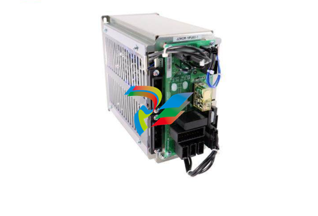
• Uses the VM600Mk2/VM600 RPS6U rack power
supply: AC and/or DC input versions
• Power supply check relay
APPLICATIONS
• VM600Mk2/VM600 machinery protection and/
or condition monitoring systems
DESCRIPTION
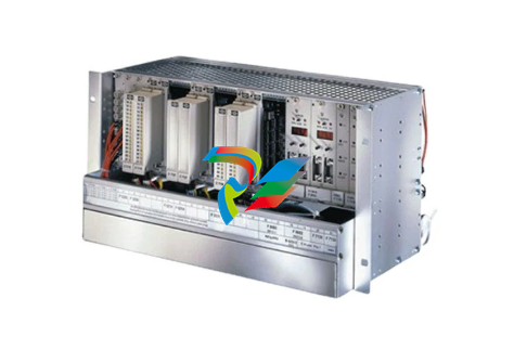
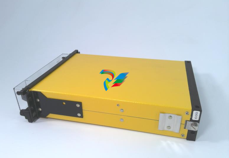
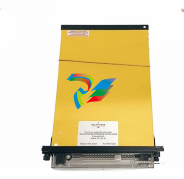
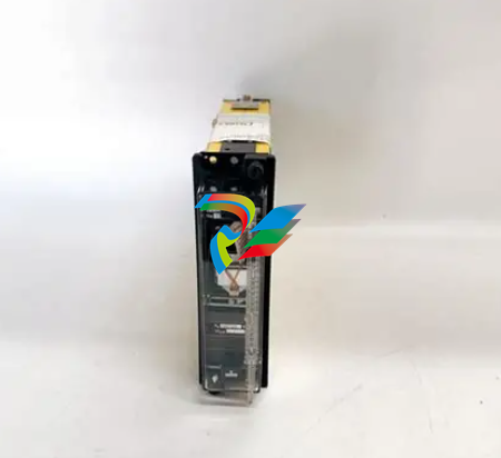
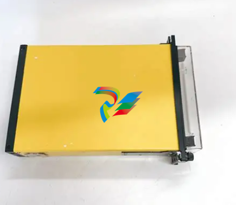
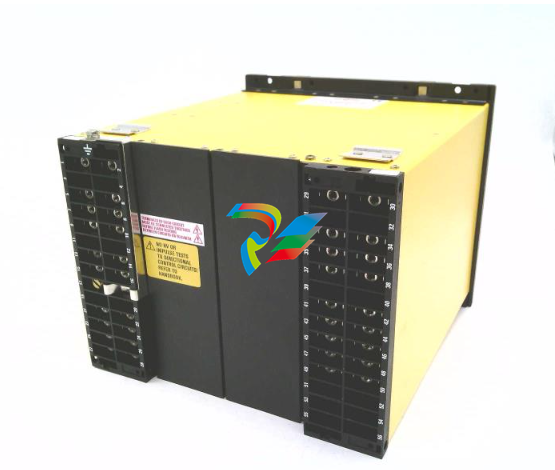
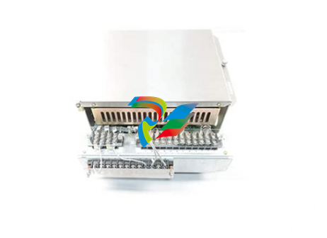
The VM600Mk2/VM600 ABE040 and ABE042 system
racks are used to house hardware for the
VM600Mk2/VM600 series of machinery protection
and/or condition monitoring systems, from
Meggitt’s vibro-meter® product line.
Two types of VM600Mk2/VM600 ABE04x system
rack are available: the ABE040 and the ABE042.
These are very similar, differing only in the position
of the mounting brackets. Both racks have a
standard height of 6U and provide mounting
space (rack slots) for up to 15 single-width
VM600Mk2/VM600 modules (card pairs), or a
combination of single-width and multiple-width
modules (cards). These racks are particularly
suitable for industrial environments, where
equipment must be permanently installed in 19″
cabinets or panels.
DESCRIPTION (continued)
The different versions of ABE04x system rack
enable different mounting options to support
various markets and applications.
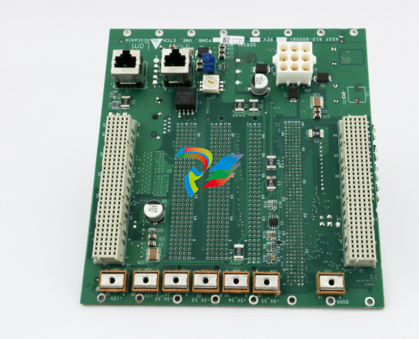
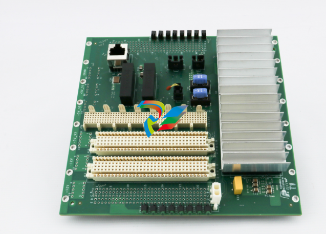
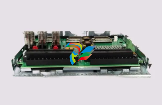
The VM600 system rack has an integrated VME
backplane which provides the electrical
interconnections between the installed
VM600Mk2/VM600 modules (cards): power supply,
signal processing, input /output, relay and
CPUx “rack controller”. It also includes a power
supply check relay, available at the rear of the
rack, which is used to indicate that the installed
RPS6U rack power supplies are operating
normally.
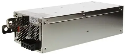
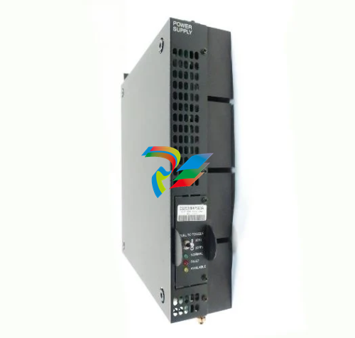
Either one or two RPS6U rack power supplies can
be installed in a VM600Mk2/VM600 ABE04x system
rack. A rack with one RPS6U power supply (330 W
version) supports the power requirements for a full
rack of modules (cards) in applications with
operating temperatures up to 50°C (122°F).
Alternatively, a rack can have two RPS6U power
supplies installed in order to either support rack
power supply redundancy or in order to supply
power to the modules (cards) non-redundantly
over a wider range of environmental conditions
(see Power supply on page 4).
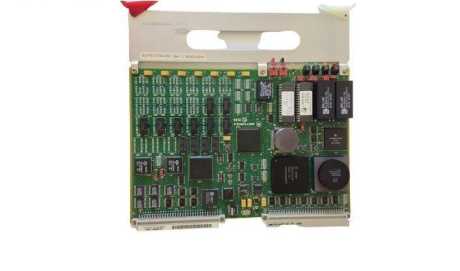
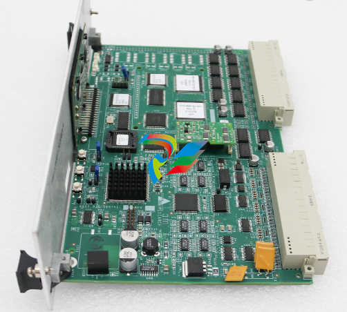
VM600Mk2/VM600 processing modules (cards) are
installed in the front of the rack and the
associated input/output modules (cards) are
installed in the rear. The input/output modules
(cards) provide connectors for the connection of
sensors/measurement chains and for the sharing
of various signals with external systems such as a
DCS or PLC.
In general, VM600Mk2/VM600 ABE04x system racks
are configured in the factory before delivery so
they are supplied ready-to-use. Optionally, each
module (card) can be reconfigured to meet the
needs of a particular machinery monitoring
application using the appropriate software
package from Meggitt vibro-meter®:
VM600 MPSx or VibroSight®.
For further information, contact your local
Meggitt representative.
General
Housing : Extruded aluminium frame and solid aluminium structural parts.
Top and bottom plastic guide strips for VM600Mk2/VM600 modules
(cards).
Colour : Aluminium
Power supply : The VM600Mk2/VM600 RPS6U rack power supply is used to provide
the VM600Mk2/VM600 rack itself and all installed modules (cards)
with +5 VDC and ±12 VDC.
See also Power supply on page 4.
Power supply inputs : Power supply inputs (associated rear panels) typically have an AC
and/or DC connector (with RFI filters), on/off switches and fuses.
Refer to the VM600Mk2/VM600 RPS6U rack power supplies
data sheet for information on power supply inputs, associated rear
panels and mains power supply leads (power cords).
Backplane : Proprietary VM600Mk2/VM600 rack buses (Tacho bus, Raw bus and
Open collector (OC) bus) for data/signal sharing between modules
(cards).
VME bus for communication between CPUx modules (cards) and
processing modules (cards).
Rack slots
(module (card) positions)
: Front of rack:
• 12 × slots – module (card) positions 03 to 14 – for processing
modules (cards) such as MPC4Mk2, XMx16, MPC4 and/or AMC8.
• 2 × slots – module (card) positions 00 to 01 – for rack controller
and communications interface modules (cards) such as CPUMMk2
or CPUx.
• 1 × slot – module (card) position 02 – reserved for applicationspecific modules (cards).
Rear of rack:
• Up to 19 × slots – module (card) positions 00 to 18 – for associated
input/output modules (cards) such as IOC4Mk2, XIO16T, IOC4T and/
or IOC8T, IOCNMk2 or IOCx, and relay modules (cards) such as
RLC16Mk2, RLC16 and/or IRC4.
• Up to 4 × slots – module (card) positions 17 to 20 – for associated
