
LAMBDA LZS-A1500-3-001 POWER SUPPLY
LZS-A1500-3-001 POWER SUPPLY
1 Safety and Recommended Practices
1.1 General Safety Instructions
This power supply is a switch mode power
supply for use in applications meeting a
Pollution Degree 2 environment. A suitable
mechanical and fire enclosure must be
provided by the end use equipment for
shock hazard protection, fire protection
and protection from hazardous energy lev
els.
READ SAFETY INSTRUCTIONS carefully
before working on the unit.
HIGH VOLTAGE WARNING: Dangerous
voltages are present within the power
supply.
NO USER SERVICEABLE PARTS
INSIDE.
1. Do not install, test or operate this product
near water, and do not spill any liquid on it.
2. Do not operate this product unless it is
in a secure position.
3. This product must be installed and put
into service by authorized competent
personnel only who are fully conversant
with the hazards of AC line operated
equipment and with the particular dangers
associated with switch mode power
supplies.
4. This product is designed for use within
other equipment or enclosures which
restrict access to authorized competent per
sonnel only and must not be user accessi
ble.
5. This product must be reliably earthed
and professionally installed in accordance
with the prevailing electrical wiring regula
tions and safety standards. The product's
PE connection is via the tapped standoff
and screw on the front panel marked with
IEC 60417-1 Symbol 5019.
6. The case is connected to the product's
PE connection with screws. Therefore,
screws at the case must not be removed or
loosened.
7. The output power taken from the power
supply must not exceed the rating stated
on the power supply label.
1-800-LAMBDA-4
8. Openings in the product case are
designed for ventilation and must not be
obstructed when the product is installed and/
or operated.
9. Never push objects of any kind into the
product through openings in its case as
this could result in electric shock or fire
hazard.
10. Use copper stranded wire only, 12 to 14
AWG rated at 105°C for the AC input. All
strands must be secured in the terminal
block to avoid potential danger of short
circuit.
11. Properly torque AC input terminals to 9 in-lb.
12. An internal fuse protects the unit and
must not be replaced by the user. In case
of internal defect, the unit must be
returned to the manufacturer.
13. The output of this power supply is haz
ardous and must not be user accessible in
the end use equipment. The (+) or (-) output
can be earthed. Use wire rated at 105°C
and sized for 150% of the rated load.
14. The unit contains components that
require special disposal. Make sure that
the unit is properly disposed of at the end
of its service life.
1.2 Safety Agency Approvals
Regulatory agency compliance applies
only for operating frequencies between
47-63Hz.
No safety agency approvals for 100-380VDC
operation.
This product is approved to UL/CSA
62368-1. 3rd Ed, IEC/EN 62368-1:2014.
UL 508 Edition 18.
The CE Marking, when applied to a product
or packing material for a product covered
by this handbook, indicates compliance with
the EMC Directive, Low Voltage Directive
and RoHS Directive.
The UKCA Marking, when applied to
a product or packing material for a
product covered by this handbook,
indicates compliance with the Electrical
Equipment (Safety) Regulations and
Restriction of the Use of Certain
Hazardous Substances in Electrical &
Electronic Equipment Regulations.
Emissions
Table 1
AC Line Conducted Emissions EN55022/EN55011 (0.15-30 MHz) Class B
Radiated RF Emissions EN55022/EN55011 30-1000 MHz Class B
Powerline Harmonics EN61000-3-2 Class A Limits
Powerline Fluctuation/Flicker EN61000-3-3 Complies
Immunity
Electrostatic Discharge IEC61000-4-2 +/-8 kV Air
+/-6 kV Contact
RF Radiated Fields IEC61000-4-3 10 V/m, 80 MHz-2.5GHz
80% AM @ 1kHZ
Electrical Fast Transients IEC61000-4-4 +/-2 kV AC Line, Criteria A
+/-1 kV I/O Line > 3m, Criteria A
Lightning Surge IEC61000-4-5 +/-2 kV line to GND (CM), Criteria A
+/-1 kV line to line (DM), Criteria A
Conducted RF Common Mode IEC61000-4-6 10 V/m RMS, 150 kHz-80 MHz
80% AM at 1kHz
Power Frequency Magnetic Field IEC61000-4-8 3 A/m
Voltage Dips/Short Variations IEC61000-4-11 5% of nom. line for .5 cycles - Criteria A
40% for 5 cycles - Criteria A
70% for 25 cycles - Criteria A
95% Dip for 5 seconds
Unit should not latch
SEMI-F47 50% of nom. line for 200 msec
(110 VAC@1000W, 70% for 500 msec
220 VAC@1500W) 80% for 10 seconds
90% for 15 seconds
0% for 1 cycle or 20mS
Additional Immunity
Ring Wave Lightning Surge Test IEEE C62.41 6 kV/30 Ohm Criteria A
Maximum Ratings
Units LZS-A1500-3
Output Voltage Range V 18-29.4
Output Current (Power) @ 60°C** A(W) 63 (1512)
DC Output @ 24V
Output Current (Power) @ 70°C** A(W) 37.8 (907)
Operating Temperature °C 100% rated load from -30°C to 60°C derate linearly to
60% @ 70°C (4%/°C)
Start-up Temperature °C -40° to +70°
Input Specifications
Units LZS-A1500-3
Input Voltage Range*** VAC Input Voltage Range*** VAC 85-265 (47-440Hz) Single phase;
VDC 100-380
Input Current (RMS, maximum) A 18 RMS
Inrush Current (Peak, at cold start) A 30A/110VAC; 40A/220VAC
Power Factor Harmonics - EN61000-3-2 Compliant
Power Factor (at max output power) - 0.98 typical @ 170VAC
Input Power (maximum) W 1800W @ 63A (1512W) and 170VAC line
Input Surge Protection - 1kV Differential Mode; 2kV common mode
Input EMI Conducted Emissions - FCC Class B, CISPR 22 Class B
Efficiency (at max. output power) % 84 typical @ 110VAC line
LZS-A1500-3 Output De-rating
85 VAC 18 63 1134 62.50 1125 37.50 675
(120 VDC) 24 50 1200 46.90 1125 28.20 675
29.4 40.8 1200 38.30 1125 23.00 675
90 VAC 18 63 1134 63.00 1134 40.00 720
(127 VDC) 24 54.2 1300 50.00 1200 30.00 720
29.4 44.2 1300 40.80 1200 24.50 720
95 VAC 18 63 1134 63.00 1134 42.50 765
(134 VDC) 24 58.4 1400 53.10 1275 31.90 765
29.4 47.6 1400 43.40 1275 26.10 765
100 VAC 18 63 1134 63.00 1134 45.00 810
(142 VDC) 24 63 1512 56.30 1350 33.80 810
29.4 51.4 1512 46.00 1350 27.60 810
105 VAC 18 63 1134 63.00 1134 47.50 855
(148 VDC) 24 63 1512 59.40 1425 35.70 855
29.4 51.4 1512 48.50 1425 29.10 855
110-265 VAC 18 63.00 1134 50.30 907
(155-380 VDC) 24 63.00 1512 37.80 907
29.4 51.40 1512 37.80 907
Output Performance Specifications
Units LZS-A1500-3
Voltage Line Regulation % 0.1
Voltage Load Regulation % 0.1
Ripple and Noise @ 20 MHz measurement
Bandwidth. EIAJ RC-9002A procedure. (PARD-mVP-P) 75
Temperature Coefficient %/°C .01
Startup Time (at 110 VAC input) Sec. Less than 1 second
Overshoot mV No overshoot at turn on or turn off
Holdup Time (Full Power/220VAC) mS 10
Ride through (Full Power/220VAC) mS 20
Voltage Sag Immunity (Full Power/110VAC) - Semi-F47 compliant
Load Transient Response +/-1% of Vo ; 1A/S; Recovers to within
(25% step load change) - +/-0.2% in < 1.25 mS
Operating Modes
Table 6
Series Operation Yes (see Fig. 7)
Parallel Operation Two or more identical units (see Fig. 6). (Use of D. con. terminal 5 will
(with current sharing) provide current sharing to within 10% nominal of rated 60°C current.)
DC Output Controls and Indicators
Output Voltage Adjust Screwdriver adjustment over entire range. Output voltage range is from
18-29.4V. (Multi-turn potentiometer accessible from terminal end of chassis.)
Overvoltage Protection Adjust Screwdriver adjustment over entire range. Overvoltage trip range is from
20-34V. Factory setpoint is 31.0V. (Multi-turn potentiometer accessible
from terminal end of chassis.)
Output Good Indicator Green colored LED illuminates when output is within specified operating range
Fault Indicator Red colored LED illuminates if overvoltage, overtemperature, or overcurrent
shutdown occurs. The LED is also illuminated if the output is less than approximately
95% of its adjusted output or if the output is inhibited (stand-by mode).
Remote Control Features
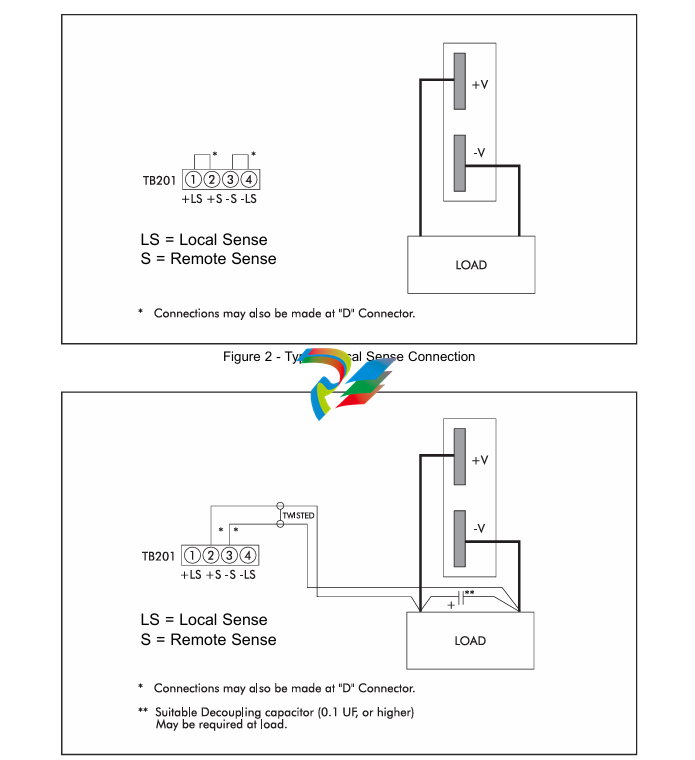
Remote Voltage Sensing Provides precise regulation directly at load (see Fig. 3). Maximum total
DC voltage drop between output terminals and load must be limited to
<1.0 V. In addition, the voltage at the output terminals must be limited to
29.4V.
Remote Voltage Programming 1000 ohms per volt for resistor connected between pins 1 and 2
external resistor. on TB201 (see Figs. 4 and 5).
Remote Voltage Programming Volt per volt for voltage source connected between pins 1 and 2
external voltage source. on TB201 (see Figs. 4 and 5).
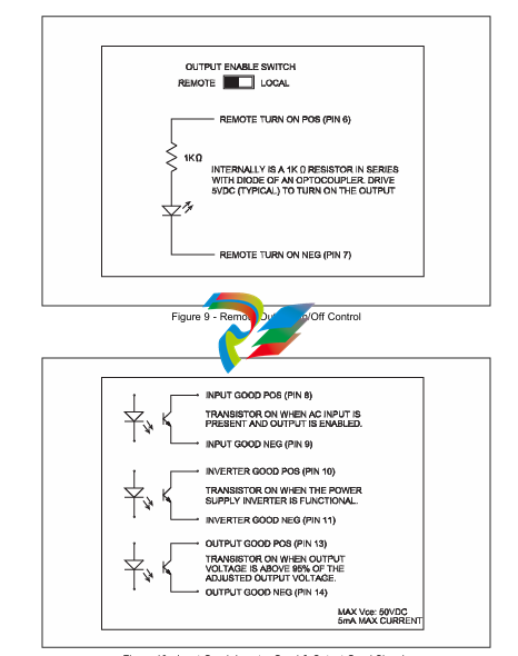
Remote On/Off Control Enable/Disable output via TTL compatible signal connected between
pins 6 and 7 of “D” connector (see Fig. 9).
Signals Isolation Pins 6 and 7 are fully isolated from all other power supply terminals.
Signal Logic Logic zero (below 0.7 V), short circuit or open circuit disables power
supply output. Logic one (above 2.5 V) enables power supply output.
Signal Current Draw Current draw from Logic 1 input is less than 4mA.
Output Response Time Output will be within specified limits within 100 ms. of application of
logic “1” signal.
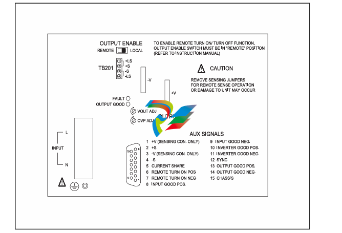
Signal Enable Remote on/off function must be enabled by moving “OUTPUT ENABLE”
switch at terminal end of chassis from “LOCAL” to “REMOTE” position (see Fig. 9).
Auxiliary Monitoring and Alarm Signals
Optically coupled, conductance outputs. (Conduct up to 1mA at a voltage of <0.4 V, when active.)
Input Power Good Signal Conductance signal which indicates adequate input capacitor voltage to
provide 10 ms holdup time when operating at full output power.
Signal will be asserted when the unit is remotely disabled (AC still present)
or when unit shuts down due to overtemperature (see Fig. 10).
Output Good Alarm Signal Conductance signal which indicates that delivered output voltage, as measured at
the +V and -V terminals, is above its minimum specified value (see Fig. 10).
Inverter Good Signal Conductance signal which indicates that the power supply’s inverter is
functional. At very light loads, this signal may be indeterminate (see Fig. 10).
Signal Isolation Input power good, output UV/OV alarms, inverter good and remote on/off
signals are isolated from power supply output and each other for voltages up
to 500 volts, minimum. 3000 VAC isolation from AC input to all auxiliary signals.
Synchronization (Sync) Auxiliary signal at approximately 200khz (switching frequency of unit) used for
synchronizing with other equipment
Protection Features
Table 10
Output Voltage Range V 18-29.4V
Nominal Factory Set Point V 24V
Overvoltage Protection (adjustable) V 20-34V (Factory set to 31.0V)
Overcurrent Protection - Factory set to 110% min. and 130% max.
Thermal Protection - Self-resetting thermostat.*
Fusing - Internal
Isolation Voltages - 4242 VDC, Input to Output
2121 VDC, Input to Chassis Ground
500 VDC, Output to Chassis Ground
Regulatory Agency Compliance - UL 62368-1. CSA C22.2 No. 62368-1
UL508. CSA C22.2 No. 107.1
EN62368-1
IEC62368-1
IEC61000 2nd Edition, Semi F47
Leakage current (AC line to μA Less than 1.5 mA @ 265 VAC, 60 Hz
chassis ground)
Mechanical Features
Units
Table 11
Storage Temperature (non-operating) °C -40°C - +85°C
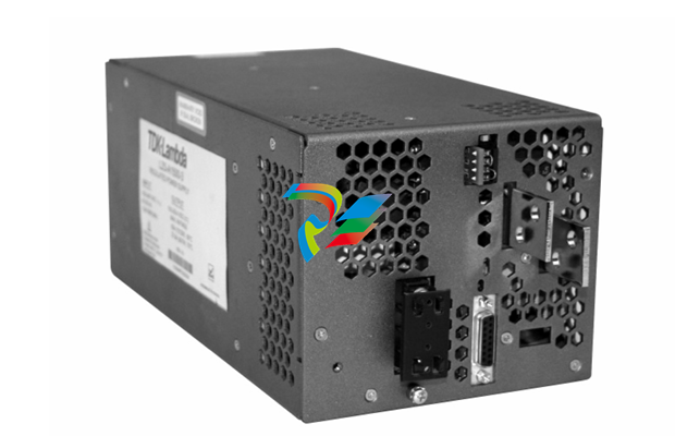
Weight lbs 9.2 lb net
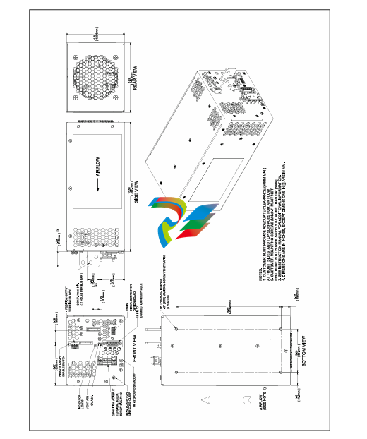
Size inches 5.62” x 4.75” x 10.5”
Finish - Textured gray - painted
Mounting - One mounting surface (mounting position not restricted)
Maximum allowable penetration into power supply is
1/4”. Requires No. M4 (metric) hardware - supplied
with unit.)
Input and Output Connections
Table 12
Input Heavy duty terminal block
Chassis Ground Tapped hole and screw provided in chassis.
DC Output Heavy-duty bus bars with 1/4” clearance holes for load connections.
(Connection hardware supplied with unit.)
Local/Remote voltage sensing, Four-position lugless connector (TB201), see Fig. 1.
Remote on/off, Parallel operation. (Accepts up to #14 AWG size stripped wire).
Auxiliary Control and Alarm Signals Connections for remote and local sens
. GUIDE TO APPLICATION
4.1 SAFETY NOTICE
Dangerous voltages exist in this equipment. Observe the usual safety precautions when operat
ing, wiring, or servicing to reduce the risk of shock or injury.
4.2 INPUT VOLTAGE
See Table 3 on page 4.
4.3 OUTPUT VOLTAGE
This power supply operates as a constant-voltage source with maximum load ratings as listed
on page 3. If the load current tries to exceed 110% of the 60°C rating, the output voltage will
begin to decrease, thereby limiting the power delivered to the load. Upon removal of overload,
normal operation will resume.
When shipped from the factory, the power supply is ready for use with output voltage (Vout) set
to its nominal rating of 24.0V. Jumpers are in place on TB201 for local voltage sensing. Where
precise regulation is required directly at the load, remote voltage sensing can be utilized. This
can be achieved by utilizing the remote sense terminals on TB201 or "D" connector (see Figs.2
and 3). The output voltage can be increased by turning the Vout adjust potentiometer clock
wise. The output voltage is decreased by turning the Vout adjust potentiometer counter clock
wise.
As shown on page 4. LZS-A1500 power supplies have both a maximum current rating and a
maximum output power rating (as a function of ambient temperature and input voltage). Care
should be taken to limit both output current and output power to be within specified limits. If
these limitations are not adhered to, the internal thermal protection circuit may shut down the
power supply's operation. For remote voltage sensing, the maximum limits for output power, as
given on page 4. apply at the power supply output terminals, not at the remote sensing point.
When adjusting the output voltage above 24.0V, ensure that there is sufficient OVP margin with
respect to the output voltage, to avoid nuisance tripping.
4.4 OVERVOLTAGE PROTECTION CIRCUIT ADJUSTMENT
The overvoltage protection circuit provides an adjustable means of disabling the DC output if it
should exceed a pre-determined safe value. When shipped from the factory, the overvoltage
level on each LZS unit is set as given in table 7 on page 5. If a different OVP threshold is
required, it can be adjusted using the following method:
1. Turn the OVP Adjust potentiometer fully clockwise (at least 10 turns).
2. With the power supply unloaded, set Vout to the OVP threshold desired. In cases where the
desired OVP threshold exceeds the unit’s adjustment range maximum of 29.4V, a programming
resistor (see figures 4 & 5) will temporarily be needed to provide the higher output voltage to
perform the adjustment. Once adjusted, remove the programming resistor. Alternatively, you
may use an external voltage source to set the OVP threshold as shown in figures 4 & 5.
3. Slowly turn the OVP adjust control counter clockwise while monitoring the output voltage.
Stop turning the control immediately when the red FAULT indicator lights, indicating an OVP
shutdown. At that point, the OVP threshold is set to the desired value.
4.5 OVERTEMPERATURE AND OVERVOLTAGE SHUTDOWN
LZS-A1500 power supplies will automatically shut down if operating conditions cause excessive
internal heating or excessive output voltage. After the occurrence of an overvoltage shut down,
input power must be interrupted or the remote on/off feature must be toggled to re-establish the
output. Overtemp shutdown resets itself once the unit has cooled off by approximately 10°C.
4.6 AUXILIARY CONTROL AND ALARM SIGNALS
LZSa power supplies provide auxiliary control and alarm signals per page 5. These signals are
accessible via the 15-pin, sub miniature "D" connector, located below the output terminals of the
unit
| User name | Member Level | Quantity | Specification | Purchase Date |
|---|


-
 Basler Electric DECS-200 Digital Excitation Control System
 -
 Basler Electric GENERATOR PROTECTION SYSTEM BE1-GPS100
 -
 Jaquet FT3000 Speed measurement system
 -
 Hirschmann Industrial Ethernet Ruggedized Switch MACH1000 Family
 -
 Basler Electric BESTCOMSPlus®
 -
 ETEL AccurET MODULAR 300 EA-P2M-300-xxxxxA controller
 -
 Basler Electric ES Series Protection Relays
 -
 ABB Multifunction Protection and Switchbay Control Unit REF542plus
 -
 EMERSON AMS 2140 Machinery Health Analyzer
 -
 Hirschmann Industrial Ethernet Rail Switch RS20 Basic Family
 -
 GE Grid Solutions P40U Px40 USB Adaptor
 -
 ABB ontinuous Gas Analyzers AO2000 Series AO2040CU Ex Central Unit in Category 2G
 -
 ABB Advance Optima AO2000 Series Continuous gas analyzers Models AO2020. AO2040
 -
 Advance Optima Module Uras 14
 -
 SAACKE control optimization
 -
 SAACKE se@vis efficiency monitor
 -
 SAACKE se@vis pro
 -
 SAACKE se@vis eco
 -
 SAACKE se@vis compact
 -
 HIRSCHMANN Industrial ETHERNET Switch MICE MS20/MS30
 -
 HIRSCHMANN MICE Media modules
 -
 Kongsberg GL-10 Level Switch
 -
 B&R ACOPOSinverter P74 frequency converter
 -
 Beckhoff CX2020 | Basic CPU module (service phase)
 -
 Beckhoff CX1010 | Basic CPU module (service phase)
 -
 Beckhoff CX5120 | Embedded PC with Intel Atom® E3815
 -
 Beckhoff CP69xx-xxxx-0010 | Economy built-in Control Panel with DVI/USB Extended interface
 -
 Beckhoff CP29xx-0000 | Multi-touch built-in Control Panel with DVI/USB Extended interface
 -
 SAACKE Monoblock Rotary Cup Burner SKVJ-M
 -
 ABB Plantguard Fault Tolerant Technology Architecture and Software
 -
 OMRON H8PR-8/H8PR-8P H8PR-16/H8PR-16P H8PR-24/H8PR-24P Rotary Positioner
 -
 ABB PFSA107-Z42 DTU Stressometer Digital Transmission Unit
 -
 Nidec Mentor MP
 -
 IBA ibaNet-E
 -
 IBA FO Connection to Reflective Memory
 -
 IBA FO Connection to Siemens Systems
 -
 IBA Interface Cards For Fiber Optic Connections
 -
 IBA Field and Drive Buses
 -
 IBA ibaPADU-S Modular System
 -
 IBA ibaMAQS
 -
 STUCKE SYMAP®ARC
 -
 STUCKE SYMAP®R
 -
 STUCKE SYMAP®Compact
 -
 MOOG G123-825-001 BUFFER AMPLIFIER
 -
 Motorola MVME5100 Series VME Processor Modules
 -
 Motorola MVME162 Embedded Controller
 -
 HIMatrix Safety-Related Controller System Manual for the Modular Systems
 -
 Motorola MVME2400 Series VME Processor Module
 -
 Sieger System 57
 -
 KONGSBERG MRU product line continuation
 -
 Woodward easYgen-3100/3200 Genset Control for Multiple Unit Operation
 -
 Woodward MFR 300 Multifunction Relay / Measuring
 -
 ABB AX410, AX411, AX413, AX416, AX418, AX450, AX455 and AX456 Single and dual input analyzers for low level conductivity
 -
 ABB AX410, AX411, AX416, AX450 and AX455 Single and dual input analyzers
 -
 Woodward easYgen-1400 Technical Manual Genset Control
 -
 Woodward easYgen-400 Operation Manual Genset Control
 -
 Woodward High Output Digital Valve Positioner (DVP)DVP5000/DVP10000/DVP12000
 -
 Woodward High Output Digital Valve Positioner DVP5000 and DVP10000
 -
 Woodward TG611-13/-17 Overspeed Test Device Conversion Kit
 -
 Woodward MicroNet Safety Module (MSM)
 -
 Woodward 2301A Electronic Load Sharing and Speed Control 9905/9907 Series
 -
 Woodward-Service Bulletin 01671
 -
 UniOP eTOP40B 12.1” TFT color display
 -
 UniOP eTOP40 TFT Color display
 -
 UniOP eTOP33B 10.4” TFT color display
 -
 UniOP eTOP33C eTOP33-0050 Resistive touchscreen
 -
UniOP eTOP30. eTOP32 eTOP32-0050 Human-machine interface equipment
-
 UniOP eTOP20B and eTOP21B eTOP20B-0050
 -
 UniOP eTOP12 eTOP12-0050 Advanced human-machine interface equipment
 -
 UniOP eTOP11 eTOP11-0050 HMI
 -
 UniOP eTOP06C HMI
 -
 UniOP eTOP06 HMI
 -
 UniOP eTOP05EB eTOP05EB-DF45 HMI
 -
 UniOP eTOP05. eTOP05P Human-machine interface equipment
 -
 UniOP eTOP03 eTOP03-0046
 -
 UniOP eTOP507 507U2P1 eTOP Series 500 Human-Machine Interface
 -
 UniOP eTOP307
 -
 UniOP ETT-VGA Human-machine interface touch unit
 -
 UniOP ePAD32B, ePAD33B and ePAD33BT ePAD33B-0350
 -
 UniOP ePAD05 and ePAD06
 -
 UniOP CP02R-04 Human-machine interface
 -
 UniOP ERT-16 - Industrial PLC Workstation
 -
 UniOP ePAD03 and ePAD04
 -
 UNIOP EPALM10-DA71 state-of-the-art handheld HMI
 -
 Watlow SERIES CLS200 SPECIFICATION SHEET
 -
 Detailed Explanation of B&R Power Panel 300/400: The Core of Industrial Automation Control
 -
 YOKOGAWA Models ANB10S, ANB10D, ANR10S, ANR10D Node Units (for FIO)
 -
 Woodward ESDR 4 Current Differential Protection Relay
 -
 Woodward easYgen-3000 Genset Control for
 -
 Woodward CPC-II Current-to-Pressure Converter
 -
 Woodward 8290-189-EPG-installation-manual 8290-044
 -
 Woodward Product Change Notification 06946A
 -
 Woodward Product Change Notification 06912
 -
 Fisher™ 4660 High-Low Pressure Pilot
 -
 Flexible digital protection and control equipment SYMAP®
 -
 Woodward 723PLUS Digital Control
 -
 Woodward 505 Digital Controller For steam turbineses
 -
 Woodward 85018V2 505E Digital Governor for Extraction Steam Turbines
 -
Woodward 85018V1 Turbine Control Parameters
-
Woodward 26871 505 Enhanced Digital Control for Steam Turbines
-
 Woodward 03365 505E (Extraction / Admission)
 -
 KONGSBERG RMP420-Remote Multipurpose Input/Output
 -
 KONGSBERG RCU501 Remote Controller Unit
 -
 KONGSBERG RCU500 Remote Controller Unit
 -
 K-Gauge TOP KONGSBERG Tank Overfill Protection SystemFeatures
 -
 Kongsberg DPS112 DGNSS (DGPS/DGLONASS) sensor
 -
 Kongsberg d0000930-presafe-atex-report signed
 -
 HIMax TECHNICAL FACTS X Series
 -
 GE Multilin F650
 -
 GE MIF II - Legacy
 -
 GE PQM II Power QualIty Meter
 -
 Hydran 201Ti Mark IV Essential DGA monitoring for transformers
 -
 alstom AMS42/84 5B Amplifier SystemAmplifier Technology at its Best.
 -
 GE VMIVME-5576 Fiber-Optic Reflective Memory with Interrupts
 -
 GE Multilin 750/760 - Legacy Feeder Protection System
 -
 GE Fanuc Automation VMICPCI-7806 Specifications
 -
 VMIVME-7807 VME-7807RC* Intel® Pentium® M-Based VME SBC
 -
 GE Fanuc Automation VMIVME-7750 Specifications
 -
 FOXBORO Compact FBM240. Redundant with Readback, Discrete
 -
 FOXBORO FBM208/b, Redundant with Readback, 0 to 20 mA I/O Module
 -
 FOXBORO FBM201e Analog Input (0 to 20 mA) Interface Modules
 -
 Foxboro DCS FBM206 Pulse Input Module
 -
 FOXBORO FBM216 HART® Communication Redundant Input Interface Module
 -
 FOXBORO Z-Module Control Processor 270 (ZCP270)
 -
 FOXBORO Fieldbus Communications Module, FCM10Ef
 -
 FOXBORO Fieldbus Communications Module, FCM10E
 -
 Foxboro DCS Compact FBM241/c/d, Redundant, Discrete I/O Modules
 -
Foxboro FBM223 PROFIBUS-DP™ Communication Interface Module


