
B&R MASYS22003-E_V40_03_2001 USERS MENAUL
1.4 MODULES
B&R SYSTEM 2003 modules are diided into four groups.
Controller
CPUs
l/o Modules
Screw-in Modules (ScrM)
The technical data indicates which group the respective modules belong to
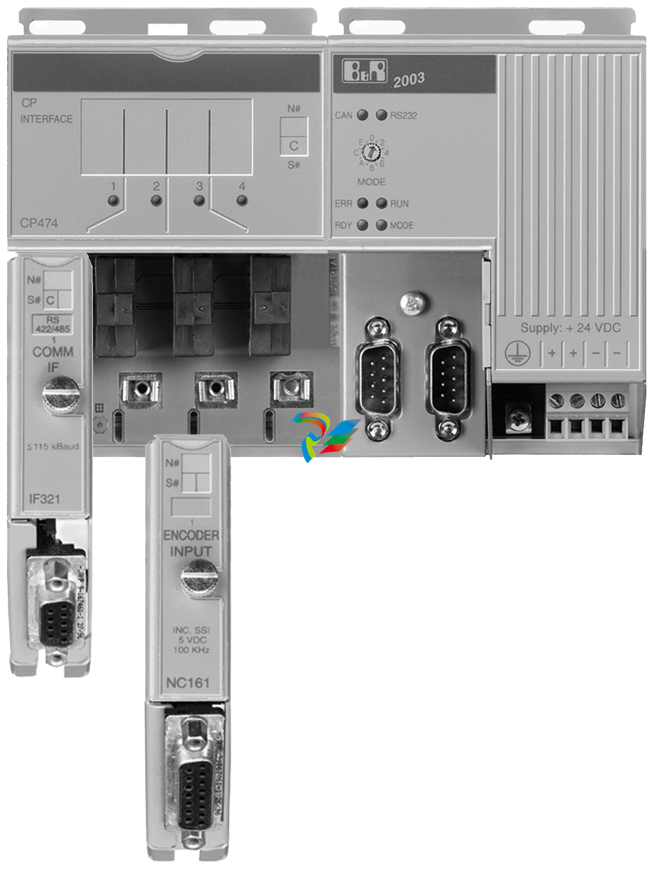
Controller, CPUand l0 mod ules are hung in the module rack and screwed to athreaded strip whichis insertedin the aluminum frame. The electrical connection between the modules is made using a 9 pin D-type plug andsocket (simply push the modules together).The risks surrounding typical ribbon cable, and inserting a module into the wrong slot no longer exist
Screw-in modules (ScrM) are installed on the adapter module or on the CP interface. Up to four screw-inmodules can be installed on each adapter module or CP interface.
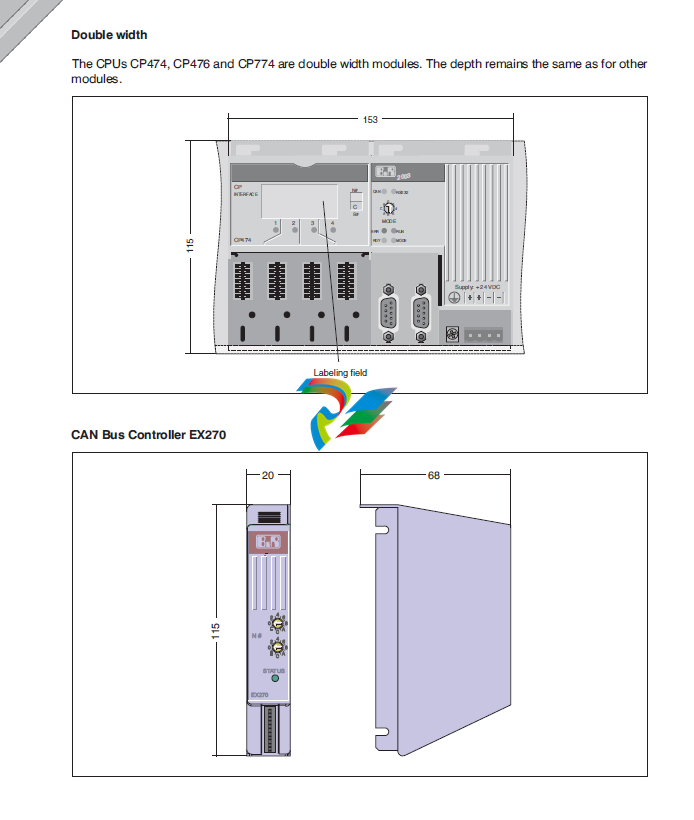
1.4.1 DimensionsController,CPUs and l/o Modules
Controller and l/0 modules are only available in single widths. CPUs are available in single or double widthsThe EX270 CAN Bus Controller is an exception. it is not hung in the module rack, instead it is screwed to theleft side of the module rack
Width:see Section "Module Rack
Height:h= 115 mm without screwin modules
h= 146 mm with screw-in modules
There must be atleast30 mm free space above the modules.The cooling vents are not allowed to be coveredUnderneath B&R SYSTEM 2003, 35mm space is to be lelt free for the input, output and supply cables
Standard Installation
Ifthe controlleris hung in the module racks, 22mm must be added to the width listedinsection"Module Racks'(column"7BP7xx.0).
Installation with CAN Bus Controller EX270
The CAN Bus Controller Ex270 is used to gether with the module racks having model numbers 7BP70x.1. TheEX270 is screwed onto the module rack instead of the left side section.31 mm is to be added to the width listed in section "Module Rack" (column "7BP70x 1")
-
 ADLINK Multi-Function DAQ PCI-9222/9223
 -
 ADLINK PICMG Single Board Computers NuPRO-A40H
 -
ADLINK HSL-4XMO HSL-4XMO-TB-D103 HSL-4XMO-CD-N-006
-
 ADLINK industrial computer motherboard NuPRO-965DV
 -
 AADLINK PCI-7442 switch card Digital I/O
 -
 ADLINK PCI-7260 Digital I/O
 -
 ADLINK PICMG Single Board Computers NuPRO-852
 -
 ADlink 6U CompactPCI 2.0 Blades cPCI-6840
 -
 Adlink PICMG Single Board Computers NuPRO-935A
 -
 ADLINK ADLINK NuPRO-841 REV:1.0 PICMG Single Board Computers
 -
ADLINK PCI-8254 / PCI-8258 DSP-based 4/8-axis Advanced Motion Controllers
-
 ADLINK NUPRO-780 PICMG Single Board Computers
 -
 ADLINK USB-7230/7250 Isolated USB Digital I/O Modules
 -
 Adlink Technology 51-37111-0C1 cPCI-R8217 cPCI-R3700A PCB Interface Card
 -
 ADLINK DPAC-3020-11(G) Embedded PC Automation Controller
 -
 ADLINK NuPRO-840 PICMG 1.0 industrial Single Board
 -
 Adlink 6U CompactPCI 2.0 Blades cPCI-6965
 -
 ADLINK PCI-9114DG Multi-Function DAQ Card
 -
 Adlink NuPRO-E43 PICMG Single Board Computers
 -
 Adlink PCI-7856 Distributed Motion Control
 -
 ADLINK Mini-ITX Embedded Boards MI-965
 -
 ADLINK NuPRO-E340 industrial control motherboard
 -
 ADLINK NuPRO-595 Series Full-Size PICMG 1.0 SBC
 -
 ADLINK PCIe-GIE64+ / PCIe-GIE62+ 4 / 2-CH PCI Express® Power over Ethernet Frame Grabbers
 -
 ADLINK CPCI-6910AM-M1G 6U Dual Core Xeon CompactPCI Universal SBC
 -
 ADLINK/AMPRO CM-435-v2/CM-435 Extreme Rugged™ PC/104 Single Board Computer
 -
 ADLINK Technology 51-37111-0C1 PCB Interface Card
 -
 Adlink Centralized Motion Controllers PCI-8164
 -
 ADLINK PCI-7230/33/34 32-CH Isolated DIO PCI Cardsrd
 -
 ADLINK NUPRO-E320DV/NUPRO-E320 industrial control motherboard
 -
 Adlink PCI-8154 Advanced 4-axis Servo & Stepper Motion Controller
 -
 Adlink cPCI-3534/3538-S Series 4/8-port Asynchronous Serial Communications Modules
 -
 ADLINK Adlink Digital I/O PCI-7396
 -
 ADLINK 6U Rear Transition Modules cPCI-R6700 Series
 -
 ADLINK cPCI-6700B Industrial Control Board
 -
ADLINK NuPRO-965/ NuPRO-965LV PICMG Single Board Computers
-
 ADLINK HSL-DI16DO16-M-NN 16-CH Discrete Input 16-CH Discrete Output Module
 -
 Adlink cPCI-6770 6U CompactPCI 2.0 Blades
 -
 ADLINK NuPRO-598 REV A1 INDUSTRIAL CONTROL MOTHERBOARD
 -
 ADLINK PCI-7200 PCI Motion Control Card Acquisition Card 51-12001-0C20
 -
 ADLINK TECHNOLOGY EOS-1200/M4G/SSD32G(G) Industrial Systems
 -
 ADLINK Centralized Motion Controllers PCI-8134
 -
 ADLINK cPCI-HR6847E/M2G-1 COMPACT PCI BOARD
 -
 ADLINK PXIE-8638 BUS EXPANSION MODULE
 -
 ADLINK cPCI-6910 6U CompactPCI 2.0 Blades
 -
 Adlink NuPRO-E42 51-41808-0A30 Industrial Motherboard
 -
 ADLINK IH61-AA400-A4A1E (IMB-M40H) Industrial Motherboard
 -
 ADLINK PCIe-GIE64+ GigE Vision Frame Grabber Card
 -
 ADLINK MXC-6322D(G) Industrial Fanless Computer working
 -
ADLINK CPCI-7300 32-CH 80 MB/s High-Speed Digital I/O Module
-
Adlink cPCI-8168 Advanced 6U Compact PCI 8-Axis Motion Controller
-
 Adlink VME CPU Board cPCI-6626/2710/M4G
 -
 ADLINK cPCI-R6200 high-performance 6U CompactPCI Rear Transition Module (RTM)
 -
Adlink cPCI-7248 48-CH Opto-22 Compatible Digital I/O Module
-
 ADLINK DLAP-211-JNX/DLAP-211-JT2/ DLAP-211-Nan
 -
ADLINK cPCI-3544 4-Port RS-422/485 Isolated Serial Communications Card
-
 Hirschmann MSP30-16040SCZ999HHE2A Manage the basic unit of the industrial DIN-Rail switch
 -
Hirschmann MSP30-16040SCY999HHE2A
-
 Hirschmann RS20-0400S2S2SDAEHC09.0.00 Management-type industrial fast Ethernet switch
 -
 Hirschmann Belden OCTOPUS OS20-002800T5T5T5-TBBY999GMSE3S Manageable industrial Ethernet switch
 -
 HIRSCHMANN OS20-000800T5T5T5-TBBU999H5SE2S
 -
 HIRSCHMANN RS20-0800M4M4SDAEHC09.0.14 industrial switch
 -
 Hirschmann RS20-0800T1T1SDAUHC RS20-0800T1T1SDAE
 -
 Hirschmann MSM20-M2M2M2M2SY9HH9E99.9 Fast Ethernet Media Module
 -
 HIRSCHMANN RS30-1602T1T1SDAEHC09.0.10 industrial switch
 -
 HIRSCHMANN MAR1040-4C4C4C4C9999SMMHPHH Managed Etherne
 -
 HIRSCHMANN MAR1040-4C4C4C4C9999SM9HRHH Managed Etherne
 -
 HIRSCHMANN MAR1040-4C4C4C4C9999SM9HPHH05.1.00 industrial switch
 -
 HIRSCHMANN MM20-P9P9M2T1SAHH Fast Ethernet media module
 -
 HIRSCHMANN MM20-P9T1T1T1SAHH hot-swappable hybrid media module
 -
 HIRSCHMANN MM20-Z6Z6T1M2SAHH Fast Ethernet media module
 -
 HIRSCHMANN MM20-Z6M2M2T1SAHH Fast Ethernet media module
 -
HIRSCHMANN MM20-Z6Z6Z6T1SAHH media module.
-
 HIRSCHMANN MM20-Z6T1T1T1EBH Fast Ethernet media card.
 -
 Hirschmann MM20-Z6T1T1T1SAHH Hot-swappable fast Ethernet media module
 -
 Hirschmann MM20-Z6Z6M2M2EBH media module
 -
 HIRSCHMANN MM20-Z6Z6T1T1SZHH Technical Datasheet & SEO Guide
 -
 HIRSCHMANN MM20-Z6Z6T1T1EBH Technical Datasheet & Overview
 -
 HIRSCHMANN MM20-Z6Z6Z6Z6SZHH Media Module
 -
 HIRSCHMANN MM20-M4M2M2T1SAHH Media Module
 -
.png) HIRSCHMANN MM20-M4T1M2T1SAHH Media Module
HIRSCHMANN MM20-M4T1M2T1SAHH Media Module -
 HIRSCHMANN MM20-M2M2T1T1EBH Media Module
 -
HIRSCHMANN MM20-M2M2T1T1SAHH Media Module
-
HIRSCHMANN MM20-M2T1T1T1TAHH Media Module
-
HIRSCHMANN MM20-M2T1T1T1EBH Media Module
-
 HIRSCHMANN MM20-M2T1T1T1SAHH Media Module
 -
 HIRSCHMANN MM20-M2M2M2M2EBH Industrial Ethernet Media Module
 -
HIRSCHMANN RS20-1600S2S2SDAEHH09.0.14 Ethernet switch
-
 HIRSCHMANN MSM20-M2M2T1T1SY9HH9E99.9.99
 -
HIRSCHMANN MSM20-M2M2M2M2SY9HH9E Ethernet media modul
-
 HIRSCHMANN SPIDER-PL-20-05T1999999TWVHHHH Industrial Ethernet Rail Switch
 -
 Hirschmann SPIDER-PL-20-07T1M2M299TWVHHHH Industrial ETHERNET Rail Switch
 -
Hirschmann (Belden) RS20-1600M2M2SDAEHC09.1.00 DIN-rail managed industrial Fast Ethernet switch
-
 Hirschmann (Belden) RS30-1602O6O6TDAPHC09.1.00 DIN-rail managed industrial Ethernet switch
 -
 Hirschmann (Belden) RS30-2402O6T1SDAPHH09.0.13 DIN-rail industrial Ethernet switch
 -
Hirschmann (Belden) SPIDER-PL-20-04T1S29999TY9HHHH Ethernet DIN-rail switch
-
 HIRSCHMANN RS20-1600T1T1SDAUHX Switch
 -
 HIRSCHMANN BRS42-0012OOOO-SPCZ99HHSES industrial switch
 -
 Hirschmann RS20-0800S2S2TDHPHH09.0.14 Fast Ethernet DIN rail switch.
 -
HIRSCHMANN MM20-Z6Z6M2M2SAHH Hybrid Fast Ethernet Media Module
-
HIRSCHMANN MM20-Z6Z6T1T1SAHH hot-swappable hybrid Fast Ethernet Media Module
-
 HIRSCHMANN MM20-P9P9T1T1SAHH Hybrid Fast Ethernet Media Module
 -
 HIRSCHMANN MM20-M4T1T1T1SAHH Hybrid Fast Ethernet Media Module
 -
HIRSCHMANN MM20-M4M4T1T1SAHH Hybrid Fast Ethernet Media Module
-
 HIRSCHMANN MM20-M2M2M2M2SZHH Ethernet media module
 -
HIRSCHMANN MM20-M2M2M2M2SAHH Ethernet media module
-
 HIRSCHMANN MM20-T1T1T1T1EBH 4-port Fast Ethernet Copper Cable Media Module
 -
HIRSCHMANN MM20-T1T1T1T1SAHH 4-port Fast Ethernet Copper Cable Media Module
-
HIRSCHMANN MM20-Z6Z6EBH Hot-swappable fast Ethernet media module
-
HIRSCHMANN MM20-Z6Z6SAHH Ethernet media module
-
HIRSCHMANN MM20-Z6Z6Z6Z6EBH Industrial Media Module
-
 MSM40-T1T1T1TZ9HH9E99.9.99 HIRSCHMANN Switch
 -
 HIRSCHMANN MS20-0800SAAEHC / MS20-0800SAAEHC0 8-port modular Layer 2 management Ethernet switch
 -
 Hirschmann RSPM20-4T14T1SZ9HHS9 Switch RSPM20-4T14T1SZ9HHS9
 -
 HIRSCHMANN RS20-1600M2M2SDAEHH09.1. RS20/30/40 Managed Switch configurator
 -
HIRSCHMANN RS20-1600M2M2SDAEHX09.0.00 Ethernet switch
-
 HIRSCHMANN BELDEN SPIDER-PL-20-07T1M2M299TY9HHHH / SPIDERPL2007T1M2M299TY9HHHH
 -
HIRSCHMANN MM3-1FXS2/3TX1 Switching Board Module
-
HIRSCHMANN RSPE30-24044O7T99-ECCP999HHSE2A08.1.00 Industrial-grade fanless management-type Ethernet switch
-
 HIRSCHMANN RS30-1602OOZZSDAEHC09.1.00 DIN-rail-mounted managed Layer 2 Ethernet switch
 -
 HIRSCHMANN MACH104-20TX-F Managed 24-port Full Gigabit 19" Switch
 -
 HIRSCHMANN Switch RS20-0800M4M4SDAE
 -
Hirschmann RS30-1602O6O6SDAEHH09.1. Management-type Ethernet switch
-
 Hirschmann RS30-1602OOZZSDAEHC09.0.10 Open rack-style Ethernet switch
 -
 HIRSCHMANN RSPE30-24044O7T99-SCCV999HHSI2SXX.X.XX High-Availability Seamless Redundancy
 -
HIRSCHMANN RSPE30-24044O7T99-SCCZ999HHSE2A DIN-rail Ethernet switch
-
HIRSCHMANN MM2-4TX1-EEC switch
-
HIRSCHMANN MSM40-T1T1T1T1TZ9HH9E99.9.99 Module


