
ABB FT-IR Gas Analyzer MBGAS-3000
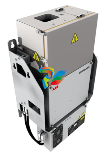 The ABB MBGAS-3000 FT-IR gas analyzer is mainly used for real-time analysis of multiple gas components during the combustion process. Its specific functions include: continuous monitoring of gas components: continuously and simultaneously measure the concentrations of up to 25 gases, such as SO2, HF, HCL, NOx, CO, CO2, NH3, H2O, etc. High-precision analysis: Based on Fourier Transform infrared spectroscopy (FTIR) technology, it offers high stability, sensitivity and measurement accuracy. Applied to emission monitoring in compliance with regulations: It meets emission standards such as EN15267-3:2008-3, provides predefined combustion monitoring analysis, and is suitable for fields such as waste incineration and industrial processes. Data recording and transmission: The design complies with HJ75 and HJ76 standards, recording and transmitting minute, hour, day, month and year data reports, and providing historical data query. Adapt to complex environments with high temperature and high humidity: Utilizing hot/wet sample extraction technology, it does not require water removal, adapting to high humidity and corrosive gas environments and avoiding sample distortion. Low maintenance: Long-life infrared light sources, on-site maintenance-free modules and maintenance-free interferometers reduce maintenance costs. System integration and maintenance are easy to integrate: It can be installed on a wall or a 19-inch rack, and the modular design facilitates on-site maintenance. Fast response: The long optical path detection cell and low-capacity design achieve a fast response time. In conclusion, the ABB MBGAS-3000 is a powerful gas analysis instrument suitable for various industrial environments, capable of providing accurate and reliable gas composition monitoring.
Technical Specifications and technical principles: Fourier Transform Infrared Spectroscopy (FTIR) technology. Measured components: It can continuously monitor various gas components in flue gas such as HF, SO22, HCl, NO xx, CO, CO 22, NH 33, H 22 O, and O 22. Measurement range: Different measurement ranges can be customized according to specific gas components and customer requirements. Wavelength range: 600-105000px −1−1. The optical path of the detection cell is 3.24 meters. Performance features: Stability: It has excellent stability and can provide accurate measurement results. Sensitivity: High sensitivity, capable of detecting low-concentration gas components. Repeatability: The accuracy of repeated measurements carried out by the same instrument is high. Reproducibility: The accuracy of repeated measurements by different instruments is high. The system consists of a gas sampling pretreatment unit: it performs pretreatment such as filtration and heating on the sample gas to ensure its cleanliness and stability. Fourier Transform infrared analyzer: Core analytical component, based on FTIR technology for qualitative and quantitative analysis of gas components. Data acquisition and processing unit: Collects, processes and analyzes measurement data, providing real-time monitoring results and historical data query functions. Application scope: Waste incineration treatment of domestic waste, medical waste, hazardous waste, etc. Other industries: power plants, building materials industry, metallurgical industry, food industry and feed processing, etc. Other parameters: Operating temperature: All components from sampling pretreatment to detection and analysis operate at a high temperature of 180°C. Interface: It provides multiple communication interfaces, such as MODBUS RS485, S7-TCP, MODBUS RS232, etc., facilitating integration with other systems. Please note that the above parameters may not be all. Specific parameters may vary depending on different application scenarios and customer requirements. It is recommended to contact ABB directly or the relevant agent to obtain the latest product manual and technical specification sheet to get the most accurate and detailed parameter information.
The advantages of the ABB FT-IR gas analyzer MBGAS-3000 include: simultaneous analysis of multiple components: It can measure the concentration of up to 25 gases simultaneously, making it suitable for monitoring complex combustion processes. High stability and accuracy: Based on Fourier Transform Infrared spectroscopy (FTIR) technology, it features outstanding stability, sensitivity and measurement precision. Hot/wet operation: Utilizing hot/wet sample extraction technology, it does not require water removal, maintains sample integrity, and can measure gases that are easily soluble in water. Low maintenance cost: Infrared light sources have a long lifespan, and their modular design facilitates on-site maintenance, reducing maintenance costs. Fast response: Compact design with short response time, it can quickly detect changes in gas concentration. Flexible calibration: Supports single-point calibration, with short calibration time, which improves operational efficiency. Reliable and durable: The embedded software is designed with advanced technology, ensuring high system reliability and suitability for various industrial environments. Easy integration: It can be wall-mounted or rack-mounted, and is easy to integrate with other systems to meet different application requirements. These advantages have enabled the MBGAS-3000 to be widely applied in fields such as waste incineration, power plants, and industrial process control.
The installation of the ABB MBGAS-3000 FT-IR gas analyzer must be carried out strictly in accordance with the operation manual to ensure that the environmental conditions meet the equipment requirements. The following is a brief overview of the installation method: Before installation, confirm the environmental conditions of the installation location, such as temperature and humidity, to ensure they meet the working conditions of the equipment. Consider the external dimensions of the equipment and its distance from the wall to ensure there is sufficient space for installation and maintenance. Ensure that the floor slab at the installation location has sufficient load-bearing capacity, with a minimum load of 550kg/m². Minimize the vibration at the installation location to ensure the stable operation of the equipment. The installation location should be as close as possible to the sampling point to reduce the length of the sampling pipeline. Professional personnel are used for hoisting and positioning the equipment to ensure its stability. Use the lifting lugs on the top of the equipment for hoisting to avoid prolonged tilting. The sampling probe of the sampling system should be installed on the pre-welded flange of the chimney sampling point and sealed with a graphite gasket. Ensure that the direction and position of the sampling probe are correct to accurately collect the sample gas. The air connection should use instrument air that meets the standards to prevent damage to the equipment caused by moist air. According to the instructions in the operation manual, correctly connect the heating pipeline, the instrument air supply pipeline, the standard gas/zero gas pipeline, the back-blowing pipeline and the exhaust pipeline. Electrical connections are carried out by professional installation and commissioning personnel to ensure that all wiring is correct and error-free. This includes the connection of the main power supply, the power supply and signal line connection of the sampling system, the power supply and signal line connection of the dust meter, the power supply line connection of the heating pipeline, and the Ethernet connection, etc. After confirming that all connections are completed, conduct a pre-startup inspection, including the air supply for the instrument and the status of the filter, etc. During the installation process, the steps in the operation manual and safety guidelines should be strictly followed to ensure the correct installation and normal operation of the equipment. If you have any questions, it is recommended that you contact an ABB authorized service provider or professional technician for support and guidance.
The installation of the ABB MBGAS-3000 FT-IR gas analyzer must be carried out strictly in accordance with the operation manual to ensure that the environmental conditions meet the equipment requirements. The following is a brief overview of the installation method: Before installation, confirm the environmental conditions of the installation location, such as temperature and humidity, to ensure they meet the working conditions of the equipment. Consider the external dimensions of the equipment and its distance from the wall to ensure there is sufficient space for installation and maintenance. Ensure that the floor slab at the installation location has sufficient load-bearing capacity, with a minimum load of 550kg/m². Minimize the vibration at the installation location to ensure the stable operation of the equipment. The installation location should be as close as possible to the sampling point to reduce the length of the sampling pipeline. Professional personnel are used for hoisting and positioning the equipment to ensure its stability. Use the lifting lugs on the top of the equipment for hoisting to avoid prolonged tilting. The sampling probe of the sampling system should be installed on the pre-welded flange of the chimney sampling point and sealed with a graphite gasket. Ensure that the direction and position of the sampling probe are correct to accurately collect the sample gas. The air connection should use instrument air that meets the standards to prevent damage to the equipment caused by moist air. According to the instructions in the operation manual, correctly connect the heating pipeline, the instrument air supply pipeline, the standard gas/zero gas pipeline, the back-blowing pipeline and the exhaust pipeline. Electrical connections are carried out by professional installation and commissioning personnel to ensure that all wiring is correct and error-free. This includes the connection of the main power supply, the power supply and signal line connection of the sampling system, the power supply and signal line connection of the dust meter, the power supply line connection of the heating pipeline, and the Ethernet connection, etc. After confirming that all connections are completed, conduct a pre-startup inspection, including the air supply for the instrument and the status of the filter, etc. During the installation process, the steps in the operation manual and safety guidelines should be strictly followed to ensure the correct installation and normal operation of the equipment. If you have any questions, it is recommended that you contact an ABB authorized service provider or professional technician for support and guidance.
ABB is a global technology leader in the field of electrical and automation. It was formed by the merger of ASEA of Sweden and BBC Brown Boveri of Switzerland in 1988, and its headquarters is located in Zurich, Switzerland. The company operates in over 100 countries and regions around the world and has approximately 105,000 employees. The company's business is electrical products: providing transformers, switch cabinets, circuit breakers, etc., which are widely used in power, industrial and other fields. Automation solutions: Provide automation systems for industries such as manufacturing and transportation to enhance production efficiency. Robotics and Discrete Automation: Develop industrial robots and automation equipment for use in the automotive, electronics and other industries. Motion control: Producing motors, frequency converters, etc., to achieve precise motion control and enhance equipment performance. In 1907, ABB provided the first steam boiler to China, marking the beginning of their cooperation. In 1974, the China Business Department was established in Hong Kong, and an office was set up in Beijing in 1979. In 1994, the China headquarters was moved to Beijing, and in 1995, ABB (China) Co., Ltd. was established. At present, it has 27 local enterprises in China, with 15,000 employees and business covering more than 130 cities. The main achievements include inventing the world's first three-phase power transmission system, the first self-cooling transformer, etc., and being the first to put them into commercial application. Its products and technologies have been widely applied in numerous key projects both at home and abroad, such as the Great Hall of the People in Beijing and the Three Gorges Project. ABB is committed to promoting sustainable development and helping customers reduce their environmental impact through technological innovation. Actively shouldering social responsibilities, it is one of the most respected employers. Looking ahead, ABB will continue to be driven by innovation, promoting the integration of electrification, automation and digitalization technologies, facilitating the transformation and upgrading of global industries, and contributing to a more sustainable and efficient future.
-
 CTI 2500C-RBC-RS485 RS485 Remote Base Controller
 -
 CTI 2500C-RBC-PRF Profibus Remote Base Controller
 -
 CTI 2500C-PS-24V-35 35-Watt DC Power Supply
 -
 CTI 2500C-PS-120V-35 35-Watt AC Power Supply
 -
 CTI 2500C-R8 Eight-Slot Base
 -
 CTI 2500C-R4 Four-Slot Base
 -
 CTI 2500C-R16 Sixteen-Slot Base
 -
 CTI 2500C-2572-B Fast Ethernet TCP/IP Adapter
 -
 CTI 2500C-J750 Compact Janus PAC with 3MB Project Memory
 -
 CTI 2500C-C300 CPU with 512K User Memory
 -
 CTI 2500C-C200 CPU with 256K User Memory
 -
 CTI 2500C-C100 CPU with 128K User Memory
 -
 CTI 2500C-8-AO 8 Analog Outputs
 -
 CTI 2500C-8-AI 8 Analog Inputs
 -
 CTI 2559-FCAL Precision Calibration Connector
 -
 CTI 2559-FPC 40-Position Screw-Terminal Connector
 -
 CTI 2500-RFC PLC to RF Modem Cable
 -
 CTI 2500-40F 40-Position Standard Screw-Terminal Connector
 -
 CTI 2505 Vibration Sensor Interface Module
 -
 CTI 2554-A 4-Channel Isolated High Speed Counter Module
 -
 CTI 2553-A 2-Channel Mag Meter Input Module
 -
 CTI 2502 2-Channel High Speed Counter Input Module
 -
 CTI 2559-TC 8-Channel Thermocouple Input Module
 -
 CTI 2556-A 16-Channel Isolated Thermocouple Input Module
 -
 CTI 2556 16-Channel Isolated Thermocouple Input Module
 -
 CTI 2551-A 8-Channel Isolated Thermocouple Input Module
 -
 CTI 2559-RTD 8-Channel RTD Input Module
 -
 CTI 2557-A 16-Channel RTD Input Module
 -
 CTI 2557 16-Channel RTD Input Module
 -
 CTI 2552-A 8-Channel Isolated RTD Input Module
 -
 CTI 2534 8-Point Form-C Relay Output Module
 -
 CTI 2532 16-Point Form-A Relay Output Module
 -
 CTI 2531 32-Point Form-A Relay Output Module
 -
 CTI 2530 8-Point Form-C Relay Output Module
 -
 CTI 2562 8-Channel Analog Output Module
 -
 CTI 2560-A 8-Channel Isolated Analog Output Module
 -
 CTI 2501 8in/4out Analog Module
 -
 CTI 2558 8-Channel Analog Input Module
 -
 CTI 2555-A 16-Channel Analog Input Module
 -
 CTI 2550-A 8-Channel Isolated Analog Input Module
 -
 CTI 2599 8/16/32-Point AC Output Module
 -
 CTI 2598-8 8-Point AC Output Module
 -
 CTI 2598 8/16-Point AC Output Module
 -
 CTI 2597 8/16/32-Point DC Output Module
 -
 CTI 2596-8 8-Point DC Output Module
 -
 CTI 2596 8/16-Point DC Output Module
 -
 CTI 2595 16-Point TTL/Word Output Module
 -
 CTI 2591-EF 16-Point Isolated 11-146 VDC Output with Front Panel Accessible Fuses
 -
 CTI 2591-A 16-Point Isolated 11-146 VDC Output Module
 -
 CTI 2590-EF 16-Point Isolated 20-132 VAC Output with Front Panel Accessible Fuses
 -
 CTI 2590-A 16-Point Isolated Discrete 20-132 VAC Output Module
 -
 CTI 2589-B 8/16/32-Point Universal Discrete Input Module
 -
 CTI 2589-A 8/16/32-Point Universal Discrete Input Module
 -
 CTI 2588-8 8-Point Universal Discrete Input Module
 -
 CTI 2585 16-Point TTL/Word Input Module
 -
 CTI 2582 16-Point Isolated 125 VDC Input Module
 -
 CTI 2581 16-Point Isolated 12-56 VDC Input Module
 -
 CTI 2580 16-Point Isolated 95-132 VAC Input Module
 -
 CTI 2500-TAP RS485 Network Tap
 -
 CTI 2500-RIO-B RS485 Remote Base Controller
 -
 CTI 2500-RIO-A RS485 Remote Base Controller
 -
 CTI 2500-RBC Profibus Remote Base Controller
 -
 CTI 2515-A 100-Watt AC/DC Power Supply with Redundancy Support
 -
 CTI 2515 100-Watt AC Power Supply (MATURE - replaced by 2515-A)
 -
 CTI 2513-A 75-Watt DC Power Supply with Redundancy Support
 -
 CTI 2513 75-Watt 24VDC Power Supply
 -
 CTI 2512-A 75-Watt AC/DC Power Supply with Redundancy Support
 -
 CTI 2512 75-Watt AC/DC Power Supply
 -
 CTI 2510 125 VDC Power Supply
 -
 CTI 2500-SSB Single Slot Blank Front Panel
 -
 CTI 2500-R11-A Eleven-Slot Redundant Base
 -
 CTI 2500P-R16 Sixteen-Slot Base with High-Speed Channel
 -
 CTI 2500P-R8 Eight-Slot Base with High-Speed Channel
 -
 CTI 2500P-R4 Four-Slot Base with High-Speed Channel
 -
 CTI 2541 Redundant Processor Manager Module
 -
 CTI 2577 Profibus DP Slave Adapter
 -
 CTI 2573-MOD Serial Interface Adapter with MODBUS
 -
 CTI 2572-AF Fast Ethernet TCP/IP Adapter with Optical Fiber Connection
 -
 CTI 2572-A Fast Ethernet TCP/IP Adapter
 -
 CTI 2572 Ethernet TCP/IP Adapter
 -
 CTI 2572-B Fast Ethernet TCP/IP Adapter
 -
 CTI 2576 DeviceNet™ Scanner Module (MATURE)
 -
 CTI 2500P-ECC1 Ethernet Communications Coprocessor
 -
 CTI 2500P-JACP Janus Application Coprocessor
 -
 CTI 2500P-ACP1 Application Coprocessor (MATURE - replaced by 2500P-JACP)
 -
 CTI 2500P-J450 Janus PAC with 2MB Project Memory
 -
 CTI 2500-C400 CPU with 3072K User Memory
 -
 CTI 2500-C300 CPU with 512K User Memory
 -
 CTI 2500-C200 CPU with 256K User Memory
 -
 CTI 2500-C100 CPU with 128K User Memory
 -
 CTI 2500P-J750 Janus PAC with 3MB Project Memory
 -
 Shinkawa WHF3006M Displacement Converter
 -
Shinkawa JBP-220 (P-24-94A / P-24-94B) Circuit Board Module
-
 SHINKAWA WKN-142K5 2-WIRE VIBRATION TRANSDUCER
 -
Shinkawa FRP-321 (P-26-54A / P-26-54B) Circuit Board Module
-
 Shinkawa IOP-160 (P-25-72A / P-25-72B) Circuit Board Module
 -
 Shinkawa PK-147B-1 / PK-147A-1 Circuit Board Module
 -
 Shinkawa CPP-91A Circuit Board Module
 -
 Shinkawa FRP-177 PCB Module
 -
 Shinkawa CPP-127 (P-26-74A / P-26-74B) Circuit Board Module
 -
Shinkawa FRP-227 (P-24-86A / P-24-86B) Circuit Board Module
-
 Shinkawa MDP-104 (P-25-83A / P-25-83B) Circuit Board Controller
 -
 Shinkawa VK-143P2 High-precision eddy current sensor driver/signal conditioner
 -
 Shinkawa FRP-226 (P-24-86A / P-24-86B) Circuit Board Module
 -
Shinkawa CPP-107A P-22-99A P-22-99B Circuit Board Module
-
 SHINKAWA VW-202AL-8 Axial Displacement Sensor
 -
Shinkawa VL-202A08L-1A42 Vibration Sensor Transducer Probe
-
Shinkawa VL-202A08L-1A42 Vibration Sensor Transducer Probe
-
 Shinkawa FRP-209A & FRP-206 Wire Bonder Circuit Board Module
 -
 Shinkawa MGP-72 MGP72 P-26-50A P-26-50B Circuit Board Module
 -
 Shinkawa FRP-249 P-25-1A P-25-1B Circuit Board Module
 -
Shinkawa FRP-320 P-26-54A P-26-54B Circuit Board Module
-
Shinkawa FRP-282 P-24-35A P-24-35B Circuit Board Module
-
 Shinkawa FRP-338 P-26-54A P-26-54B Circuit Board Module
 -
 GE IS200AEPBH1B IS200AEPBH1B‑REV‑AA Pitch-Charger Control PCB Board
 -
 GE IS200EDEXG1ADA EX2100 SCR Trigger Control Board
 -
 GE 151X1207CK01SA01 IS200EDEXG1A EX2100 SCR
 -
 GE 151X1233DD02SA02 IS200AEPBH1B - Variant for pitch control charger assembly
 -
 GE 151X1233DB01SA01 IS200AEPBH1B - 10kW Wind Power Converter
 -
 GE 151X1233DB01SA01R | IS200AEPBH1B 10KW Converter
 -
GE 151X1233DD01SA02 Pitch Battery Charger (109W6931P001)
-
GE 151X1233DD01SA02 Pitch Battery Charger Assy IS200AEPBH1B
-
 GE 151X1233DB02SA02 Rev A IS200AEPBH1B Wind Turbine Converter
 -
 GE 151X1207CK02SA02 SCR 4400 V 1850 A IS200EDEXG1ADA General Electric EX2100
 -
 Triconex 3723X 32-Channel TMR Analog Input Module with HART
 -
 SHINKAWA VM-21G SIGNAL CONDITIONER SOCKET
 -
SHINKAWA VM-21R REVOLUTION SIGNAL CONDITIONER
-
SHINKAWA VM-21T DISPLACEMENT INPUT THRUST SIGNAL CONDITIONER


