
ABB2600T Series Pressure Transmitters
2600T Series Pressure Transmitters Models 265, 267, 269
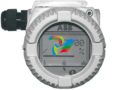
Current limitation This electronic implements also an especial circuitry for the current limitation. Whenever a fatal failure occurs and the current consumption increase over the 19 mA, this circuitry provides a limitation of the current to 19 mA, in order to save the good functionality of the other connected devices that otherwise would be switched off due to the missing power available. 3.2 Local Display The 2000T FF Pressure Transmitter is available with an integral display as optionally item, see the Figure 1. This integral display offers the possibility to display the selected variable or diagnostic strings whenever failure and/ or warnings are detected. The variable to be displayed is user selectable among several variables produced in the TB as well as the Function Blocks output in Engineering Value, or its percentage. It is selected writing the right code in the RB_METER_OPTION. See section 8.2 in the Resource Block table. – If the transmitter works correctly, the variable selected in the RB_METER_OPTION is displayed together with the unit code, and it is updated periodically. If the value is to high to show 'OVERFLOW' is displayed. – When some malfunctions are detected on the display appears the following diagnostic string sequences: 'ALARM'. The first column of the second row shows some special characters in cyclic order. This characters are the number of the shown value, write protection, transfer function, status available and EEPROM burning activ. Below the displayed value is a percent bar. The value there displayed is the OUT value of the AI1 FB at normal transmitters or the mass flow (norm volume flow) at multivariable transmitters. The display acts also as feedback of the operations performed with the external push buttons, for additional display indications see the "structure tree" Figure 3-3 on page 11.
3.3 Local Keys 3 external push buttons are available, see the Figure 2 To make the keys accessible, release the screw and turn the protection cap aside. Figure 3-2 Push Buttons View Simulation: The simulation can be activated as follows (see also symbolism on the plate). (1) First, fully press down the mode key "M" with an appropriate screw driver. 2. Then turn the switch clockwise by 90 ° angle . For deactivation the switch has to be pushed down a little and turned counterclockwise by 90 ° angle. Without display: The "-"/"+" keys have the same function like TB_SET_LOWER_RANGE and TB_SET_UPPER_RANGE. The mode ckey "M" enables/disables the simulation mode. With display: With the mode key "M", you can start menu-controlled program-ming. To call the next menu item, press the key "+". You will return via the key "- ". Submenu items / selection lists are acti-vated via the mode key "M". A numerical value can only be changed via the keys "+" and " - ". It must be taken into account that the key "+" changes the value (each keystroke increases the value by 1), whereas the position of the value to be changed is reached via the key " - ". Acknowledge changes with the mode key "M"; the subsequent OK acknowledgement (via the key "M", "+" or "-") writes the new value into the failsafe storage. An ad-justing process can be aborted by pressing simultaneously the keys "+" and "-". From any main menu item, you can return to the menu item "EXIT" by simultaneous-ly pressing the "+" and "-" keys. When the adjustment has been finished, quit the program via the menu item "EXIT". By means of the following structure tree, you will get an overview of the selection / programming possibilities.
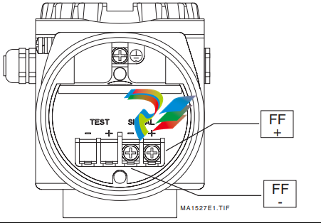
4.1 Electrical Connections The 2600 FF is a Bus Powered device with Foundation Fieldbus output. On the terminal block two screws for the BUS CONNECTION are available, see the Figure 4-4 on page 14. The Polarity has not consistency, so the two bus cables can be connected without take care about the polarity.
Device Addressing When the models 265/267/269 FF Transmitter is connected on a FF bus, the Master has to recognize it with a unique address in the world. For this reason the FF specifications define three different addressing levels that characterize the FF devices: – The DEV_ID is the unique device identifier. – The PD_TAG is the physical name of the device. – The Node Address is the real node at which the device is connected on the bus. It is automatically set by the Master (Primary LAS). The most important one with the higher priority is the DEV_ID. This is a string of 32 characters and must identify in a unique way each FF device in the world. In order to fulfill this requirement the models 265/267/269 FF applies the following mechanism: – The first part of the string is of 10 characters; the Manufacturer Code "000320" and Device Type code "0089" for 265, "008A" for 267/269. – The second part of the string is of 12 characters and represent the device type identification; "_2600T_TO___" for 265, "_2600T_MV___" for 267/269. – The third part of the string is of 10 characters and is filled with the TB_SENSOR_SERIAL_NUMBER read from the transducer database. This number is written at factory configuration stage and it is assigned in a well-defined way just to be sure to have always different numbers. Finally the DEV_ID appears of 32 characters in this way '0003200089_2600T_TO___xxxxxxxxxx', where the entire 'x' represents the Serial number. Whenever an electronics replacement after an electronics failure is necessary, appear clear that the device will be recognized on the network as before of the replacement. This is possible because the transducer, which includes the serial number, remains unchanged and the DEV_ID will be maintained the same as before of the failure.
-
 OMRON C120-LK202-EV1/C120LK202EV1
 -
 OMRON C200H-AD003 PLC
 -
 OMRON C200H-CPU23-E COIL 24VDC PLC
 -
 Omron C200HG - C200H-ID212- C200H-OC226 C200HW-BC101 PLC Base Unit
 -
 OMRON C200H-OC222(Output Unit),C200H-PS211(Power Supply Unit),SP001 Module Rack
 -
 OMRON C200H-RT201 PROGRAMMABLE CONTROLLER
 -
 OMRON C200HS-CPU01-E SYSMAC PROGRAMMABLE CONTROLLER
 -
 OMRON C200H-SNT31 C200H Programmable Controllers
 -
 OMRON C200HW-MC402-E Motion control unit
 -
 OMRON C200PC-ISA02-DRM-E PLC ISA bus compatible board card
 -
 OMRON C500-CT012 PLC
 -
 OMRON C500-NC103-E PLC
 -
 OMRON C500-NC222-E PLC
 -
 OMRON C500-PRW05-V1 PLC
 -
 OMRON C500-PRW06 PROGRAMMABLE CONTROLLER
 -
 OMRON C500-PS223-E 3G2A5-PS223-E PLC SYSMAC PROGRAMMABLE CONTROLLER
 -
 OMRON C500-TU001 3G2A5-TU001 PLC PLC
 -
 OMRON C60H-C1DR-DE-V1 Programmable Controllers
 -
 OMRON C60H-C5DR-DE-V1 Programmable Controllers
 -
 OMRON C60H-C6DR-DE-V1 Programmable Controllers
 -
 OMRON CJ1G-CPU44H CPU module
 -
 OMRON CJ1G-CPU45H PLC
 -
 OMRON CJ1M-CPU13-ETN V4.0 PLC PLC
 -
 OMRON CJ1W-AD041-V1 Analog input uni
 -
 OMRON CJ1W-CORT21 PLC module
 -
 OMRON CJ1W-IDP01 Input unit
 -
 OMRON CJ1W-MCH71 - MECHATROLINK-II
 -
 OMRON CJ1W-MD261 Digital I/O
 -
 OMRON CJ1W-NC413 Position control unit
 -
 OMRON CJ1W-NCF71 Position Control Units
 -
 OMRON CJ1W-PTS51 Process Simulation I/O Module
 -
 OMRON CJ1W-PTS52 Process Simulation I/O Module
 -
 OMRON CJ1W-SCU21-V1 PLC
 -
 Omron CJ1W-SCU22 Serial Communication Unit
 -
 OMRON CJ1W-TC001 CJ Series Temperature Control Unit
 -
 Omron CK3W-AX1515N Motion Controller
 -
 Omron CP1E-N60DR-D Compact PLC CPU
 -
 OMRON CP1E-NA20DT1-D PLC PLC
 -
 OMRON CP1H-X40DT-D plc PLC
 -
 OMRON CPM2C-S110C-DRT Interface module
 -
 OMRON CQM1-AD041 PLC
 -
 SAACKE F‑GDSA‑1 / F‑GDSA‑2 Feuerungsautomaten
 -
 SAACKE F-GDSA 143303 Controller SHIPS UPS
 -
 ICS Triplex T8270 Trusted 24 Vdc FanAssembly
 -
 SCHNEIDER M522220000 SA SM_DO16R 16 DIGITAL OUTPUTS MODULE
 -
 LENZ EPL10200-W EPZ-10203 CANPT010W3E
 -
 OMRON CQM1H-ADB21 PLC
 -
OMRON CQM1H-CPU61 PLC
-
 OMRON CQM1H-MAB42 PLC
 -
 OMRON CQM1-TC102 CQM1-TC101 PLC
 -
 OMRON CS1G-CPU44-EV1 PLC
 -
 OMRON CS1G-CPU44H CPU
 -
OMRON CS1H-CPU63-EV1 PLC
-
 OMRON CS1H-CPU66-V1 PLC
 -
 OMRON CS1W-CLK13 PLC communication module
 -
OMRON CS1W-EIP21 PLC
-
 OMRON CS1W-MAD44 PLC PLC
 -
 OMRON CS1W-SCU31-V1 CVM1-BC103 PLC
 -
 Omron CVM1-CPU21-V2 CPU Unit
 -
 OMRON F150-C10E-2 Vision Controller
 -
 OMRON F150-C15E-3 Vision Controller
 -
 OMRON F160-C15E VISION MATE CONTROLLER
 -
 OMRON F500-C10-ETN F500-C15-ETN Vision Sensor
 -
 OMRON F500-VS F500-S1
 -
 OMRON FH-3050 FH Vision Controller
 -
 Omron FQ2-S25050F PLC Smart Camera
 -
 Omron FQM1-MMA22 Motion Module
 -
 OMRON GRT1-TS2P Temperature Module
 -
 OMRON H8PR-24 Cam Positioner
 -
 OMRON IDSC-C1DR-A-E Controller
 -
 OMRON K3HB-HTA-DRT1 Temperature Panel Meter
 -
 Omron KM-N1-FLK Power Detector
 -
 OMRON CJ1G-CPU43H CPU
 -
 OMRON NA5-7W001S-V1 NA5-9W001B-V1 NA5-12W101B-V1 Graphic panel
 -
 OMRON NA5-9W001B-V1 Graphic panel
 -
 OMRON NB10W-TW01B INTERACTIVE DISPLAY
 -
 OMRON NB7W-TW01B +CP1L-EL20DR-D Complete Power Panel
 -
 OMRON NB7W-TX01B INTERACTIVE DISPLAY PLC
 -
 Omron NE1A-SCPU02 Network Controller
 -
 OMRON NA5-7W001B-V1 NA5-7W001S-V1 NA5-9W001B-V1 NA5-12W101B-V1 touch screen
 -
 Omron NS5-SQ00B-V2 NS5-SQ00-V2 NS5-SQ01-V2 NS5-SQ01B-V2 touch display panel
 -
 Omron NJ301-1100 Programmable Logic Controller
 -
 OMRON NJ501-1300 CUP Unit Programmable Controller
 -
 Omron NS12-TS01B-V2 Interactive Display
 -
 OMRON NSJW-ETN21 ETHERNET HMI
 -
 OMRON NT10S-SF121 PLC
 -
 OMRON NT20S-ST121-EV3 Touch Screen
 -
 Omron NX1P2-1140DT-BA Programmable Controller
 -
 OMRON 3G3MV-P10CDT3-E RS422/485 INVERTER BOARD
 -
 Omron C500-ID219 3G2A5-ID219 System Microprocessor
 -
 Omron PLC B7AM-8B16
 -
 OMRON PLC Module CJ1W-AD081-V1
 -
 OMRON R88D-HS10 PLC
 -
OMRON R88D-HT10 plc
-
 OMRON R88D-KN01H-ML2 Servos G5-series
 -
 OMRON R88M-H10030-B plc
 -
 OMRON R88S-H306G plc PLC
 -
 Omron Relay G9SX-GS226-T15-RT
 -
 Omron S8AS-24006N S8AS Smart Power Supply FNIP
 -
 Omron Safety Input Unit NX-SIH400
 -
 OMRON SYSMAC SCY-P1 Sequential Controller
 -
OMRON SYSMAC SCY-P0 13E Sequential Controller
-
 OMRON NS8-TV00B-V2 NS8-TV00-V2 NS8-TV00B-ECV2 NS8-TV00-ECV2 touch display Panel
 -
 Omron V680-CA5D02-V2 Programmable Controller
 -
 OMRON SGDH-04AE-OY Servo Drive
 -
OMRON SGDH-10DE-OY Servo Drive
-
 OMRON SGDS-02A12A PLC + SGMAS-C2ACA21
 -
 OMRON SGMPH-04AAA61D-OY Servo Motor
 -
 Omron ZFV-CA40 Smart Sensor Amp Unit 24VDC 0.8A
 -
OMRON ZFV-NX1 CFP0260 ZFV-A20 VISION CONTROL PANEL
-
 OMRON ZFX-C15 SMART SENSOR AMP UNIT, Vision Sensor LCD
 -
 OMRON ZFX-C20/25-CD SMART SENSOR AMP UNIT, Vision Sensor LCD
 -
 OMRON-DIGITAL TEMPERATURE CONTROLLER E5AC-CX4A5M-014 r
 -
 ABB PFVL141V-2.0MN is an industrial-grade, rectangular roll force load cell
 -
 ABB PFVL141V-1.6MN is an industrial-grade, rectangular roll force load cell
 -
ABB PFVL141V-1.25MN high-performance, rectangular roll force load cell
-
 ABB PFVL141V-1.0MN high-precision, heavy-duty rectangular load cell
 -
 ABB PFVL141V-0.8MN high-precision, heavy-duty rectangular load cell
 -
 ABB PFVL141V-0.63MN high-precision, heavy-duty rectangular load cell
 -
 GE 151X1202YE08PP08 Panel of the case / Structural component
 -
 GE 151X1212HB01MG02 Integrated LCI Controller (Old Model)
 -
 GE 151X1212GC01PC02 LCI Static Startup Controller
 -
 GE 151X1235FD01PK01 High-speed Digital Input Interface Board
 -
 GE 151X1215DK01PC01 Signal Processing / Amplification Board
 -
 GE 151X1238WP99BK01 6-pulse LCI power conversion module
 -
 GE 151X1225DF01PC03RA - Power Conversion / Drive Regulation Board
 -
 GE 151X1225DE03PC01 Drive Control Board (Terminal Control)
 -
 GE 151X1215GD01SA21 Gate Driver Board


