
ABB2600T Series Pressure Transmitters
2600T Series Pressure Transmitters Models 265, 267, 269
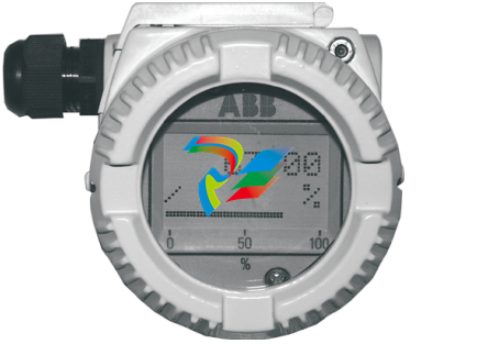
Current limitation This electronic implements also an especial circuitry for the current limitation. Whenever a fatal failure occurs and the current consumption increase over the 19 mA, this circuitry provides a limitation of the current to 19 mA, in order to save the good functionality of the other connected devices that otherwise would be switched off due to the missing power available. 3.2 Local Display The 2000T FF Pressure Transmitter is available with an integral display as optionally item, see the Figure 1. This integral display offers the possibility to display the selected variable or diagnostic strings whenever failure and/ or warnings are detected. The variable to be displayed is user selectable among several variables produced in the TB as well as the Function Blocks output in Engineering Value, or its percentage. It is selected writing the right code in the RB_METER_OPTION. See section 8.2 in the Resource Block table. – If the transmitter works correctly, the variable selected in the RB_METER_OPTION is displayed together with the unit code, and it is updated periodically. If the value is to high to show 'OVERFLOW' is displayed. – When some malfunctions are detected on the display appears the following diagnostic string sequences: 'ALARM'. The first column of the second row shows some special characters in cyclic order. This characters are the number of the shown value, write protection, transfer function, status available and EEPROM burning activ. Below the displayed value is a percent bar. The value there displayed is the OUT value of the AI1 FB at normal transmitters or the mass flow (norm volume flow) at multivariable transmitters. The display acts also as feedback of the operations performed with the external push buttons, for additional display indications see the "structure tree" Figure 3-3 on page 11.
3.3 Local Keys 3 external push buttons are available, see the Figure 2 To make the keys accessible, release the screw and turn the protection cap aside. Figure 3-2 Push Buttons View Simulation: The simulation can be activated as follows (see also symbolism on the plate). (1) First, fully press down the mode key "M" with an appropriate screw driver. 2. Then turn the switch clockwise by 90 ° angle . For deactivation the switch has to be pushed down a little and turned counterclockwise by 90 ° angle. Without display: The "-"/"+" keys have the same function like TB_SET_LOWER_RANGE and TB_SET_UPPER_RANGE. The mode ckey "M" enables/disables the simulation mode. With display: With the mode key "M", you can start menu-controlled program-ming. To call the next menu item, press the key "+". You will return via the key "- ". Submenu items / selection lists are acti-vated via the mode key "M". A numerical value can only be changed via the keys "+" and " - ". It must be taken into account that the key "+" changes the value (each keystroke increases the value by 1), whereas the position of the value to be changed is reached via the key " - ". Acknowledge changes with the mode key "M"; the subsequent OK acknowledgement (via the key "M", "+" or "-") writes the new value into the failsafe storage. An ad-justing process can be aborted by pressing simultaneously the keys "+" and "-". From any main menu item, you can return to the menu item "EXIT" by simultaneous-ly pressing the "+" and "-" keys. When the adjustment has been finished, quit the program via the menu item "EXIT". By means of the following structure tree, you will get an overview of the selection / programming possibilities.
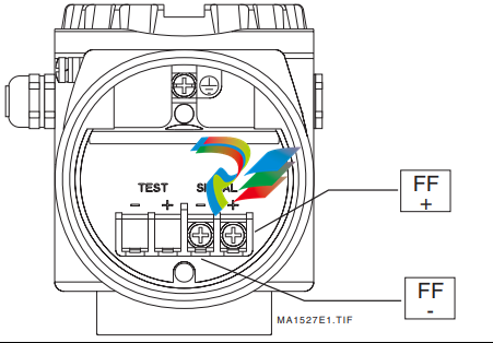
4.1 Electrical Connections The 2600 FF is a Bus Powered device with Foundation Fieldbus output. On the terminal block two screws for the BUS CONNECTION are available, see the Figure 4-4 on page 14. The Polarity has not consistency, so the two bus cables can be connected without take care about the polarity.
Device Addressing When the models 265/267/269 FF Transmitter is connected on a FF bus, the Master has to recognize it with a unique address in the world. For this reason the FF specifications define three different addressing levels that characterize the FF devices: – The DEV_ID is the unique device identifier. – The PD_TAG is the physical name of the device. – The Node Address is the real node at which the device is connected on the bus. It is automatically set by the Master (Primary LAS). The most important one with the higher priority is the DEV_ID. This is a string of 32 characters and must identify in a unique way each FF device in the world. In order to fulfill this requirement the models 265/267/269 FF applies the following mechanism: – The first part of the string is of 10 characters; the Manufacturer Code "000320" and Device Type code "0089" for 265, "008A" for 267/269. – The second part of the string is of 12 characters and represent the device type identification; "_2600T_TO___" for 265, "_2600T_MV___" for 267/269. – The third part of the string is of 10 characters and is filled with the TB_SENSOR_SERIAL_NUMBER read from the transducer database. This number is written at factory configuration stage and it is assigned in a well-defined way just to be sure to have always different numbers. Finally the DEV_ID appears of 32 characters in this way '0003200089_2600T_TO___xxxxxxxxxx', where the entire 'x' represents the Serial number. Whenever an electronics replacement after an electronics failure is necessary, appear clear that the device will be recognized on the network as before of the replacement. This is possible because the transducer, which includes the serial number, remains unchanged and the DEV_ID will be maintained the same as before of the failure.
-
 AEROTECH BLMUC-143 Linear motor forcer with thermistor
 -
AEROTECH BLMUC-111 Linear motor forcer with thermistor
-
AEROTECH BLMUC-95 Linear motor forcer with thermistor
-
AEROTECH BLMUC-79 Linear motor forcer with thermistor
-
AEROTECH BLMUC Series Linear Motors
-
 AEROTECH Automation1 FLEX Distributed Amplifier Multi-Axis Servo Control System
 -
 AEROTECH Automation1 HXA4 6-Axis Hexapod Servo Drive
 -
 AEROTECH Automation1 iHXA4 6-Axis Hexapod Servo Drive with Motion Controller
 -
 AEROTECH Modular System Control Console
 -
 AEROTECH TV Series Transformers
 -
 AEROTECH TM Series Transformers
 -
 AEROTECH UFM Noise Filter Module
 -
 AEROTECH MFM Motor Filter Module
 -
 AEROTECH MPG Handwheel Pendant
 -
 AEROTECH Automation1 Multi-Axis Joystick
 -
 AEROTECH ETM Enhanced Throughput Module
 -
 AEROTECH Automation1 XL4s High-Speed, Single-Phase Linear Servo Drive
 -
 AEROTECH Automation1 XL2e Enhanced, Compact Linear Servo Drive
 -
 Automation1 iXL2e Enhanced, Compact Linear Servo Drive with Motion Controller
 -
 AEROTECH Automation1 XL5e Enhanced, Linear Servo Drive
 -
 AEROTECH Automation1 iXL5e Enhanced Linear Servo Drive with Motion Controller
 -
 AEROTECH Automation1 GI4 Laser Scan Head Controller
 -
 AEROTECH Automation1 SI4 Stepper Interface
 -
AEROTECH Automation1 XI4 Servo Interface
-
 AEROTECH AEROTECH Automation1 iXI4 Servo Interface with Motion Controller
 -
 AEROTECH Automation1 XC6e Enhanced, High-Power PWM Servo Drive
 -
 AEROTECH Automation1 iXC6e Enhanced, High-Power PWM Servo Drive with Motion Controller
 -
 AEROTECH Automation1 XC2 Compact PWM Servo Drive
 -
 AEROTECH Automation1 XC4 PWM Servo Drive
 -
 AEROTECH Automation1 GL4 Galvo Laser Scan Head Linear Drive
 -
 AEROTECH Automation1 XC2e Enhanced, Compact Servo Drive with PWM+
 -
 AEROTECH Automation1 XC4e Enhanced, PWM Servo Drive
 -
 AEROTECH Automation1 XR3 Multi-Axis Servo Drive Rack
 -
 AEROTECH Automation1 iXR3 Multi-Axis Servo Drive Rack with Motion Controller
 -
 AEROTECH Automation1 iXC2 Compact PWM Servo Drive with Motion Controller
 -
 AEROTECH Automation1 iXC2e Enhanced, Compact PWM+ Servo Drive with Motion Controller
 -
 AEROTECH Automation1 iXC4 PWM Servo Drive with Motion Controller
 -
 AEROTECH Automation1 iXC4e Enhanced, PWM Servo Drive with Motion Controller
 -
 AEROTECH Automation1 iPC Industrial PC with Motion Controller
 -
 AEROTECH EPICS & TANGO Drivers for Distributed Control Systems
 -
 AEROTECH .NET, C, Python & LabVIEW APIs Custom Application Develotpmen
 -
 AEROTECH Automation1 Industrial Ethernet Support
 -
 AEROTECH Automation1 iSMC Intelligent, Software-Based Motion Controller
 -
 AEROTECH Automation1 iXA4 1- 2- or 4-Axis PWM Servo Drive with Motion Controller
 -
 AEROTECH Automation1 XA4 1- 2- or 4-Axis PWM Servo Drive
 -
 CTI 2500-ADP2-DISC Discrete Wiring Adapter for Series 500
 -
 CTI 2500-ADP1 Analog Wiring Adapter for Series 500
 -
 CTI 2500C-RADP-RS485 Remote Base Controller Adapter for Series 500
 -
 CTI 2500C-RADP-RBC Profibus RBC Adapter for Series 500
 -
 CTI 2500C-PADP-120V 120VAC 50W Power Supply for Series 500
 -
 CTI 2500-RADP RBC Adapter for Series 500
 -
 CTI 2500-R4500 520/530/DBC Adapter for Series 500 - MATURE
 -
 CTI 2500-PADP Power Supply Adapter for Series 500
 -
 CTI 2500-IADP I/O Adapter for Series 500
 -
 CTI 2500-VP15A-N4-W7 15" Flat-Panel PC with Windows® 7 Embedded
 -
 CTI 2500S-27-1750 Slice I/O, Ethernet, RS232/485. 900MHz, 2DIO / 4UAI / 2AI
 -
 CTI 2500S-26-1750 Slice I/O, Ethernet, RS232/485. 900MHz, 8DIO / 2UAI
 -
 CTI 2500S-23-1750 Slice I/O, Ethernet, RS232/485. 900MHz, 4DI / 4DO / 2UAI / 2AO
 -
 CTI 2500S-27-1550 Slice I/O, RS232/485. 2DIO / 4UAI / 2AI
 -
 CTI 2500S-26-1550 Slice I/O, RS232/485. 8DIO / 2UAI
 -
 CTI 2500S-23-1550 Slice I/O, RS232/485. 4DI / 4DO / 2UAI / 2AO
 -
 CTI 2500S-27-1050 Slice I/O, Ethernet, 2DIO / 4UAI / 2AI
 -
 CTI 2500S-26-1050 Slice I/O, Ethernet, 8DIO / 2UAI
 -
 CTI 2500S-23-1050 Slice I/O, Ethernet, 4DI / 4DO / 2UAI / 2AO
 -
 CTI 2500C-32F-CJC 32-Pin Field Wiring Connector with Cold Junction Compensation
 -
 CTI 2500C-32F 32-Pin Field Wiring Connector
 -
 CTI 2500C-8-TC Eight Thermocouple Inputs
 -
 CTI 2500C-8-RTD Eight RTD Inputs
 -
 CTI 2500C-8-RL-FC 8 Form-C Relay Outputs
 -
 CTI 2500C-8-IDO-24V 8 Isolated 24VDC Outputs
 -
 CTI 2500C-8-IDO-120V 8 Isolated 120VAC Outputs
 -
 CTI 2500C-16-DO-24V Sixteen 24VDC Digital Outputs
 -
 CTI 2500C-16-DO-120V Sixteen 120VAC Digital Outputs
 -
.png) CTI 500C-16-IDI-24V Sixteen Isolated 24V AC/DC Digital Inputs
CTI 500C-16-IDI-24V Sixteen Isolated 24V AC/DC Digital Inputs -
 CTI 2500C-16-IDI-120V Sixteen Isolated 120V AC/DC Digital Inputs
 -
 CTI 2500C-16-DIDO-SIM Sixteen Digital Input and Output SImulator
 -
 CTI 2500C-16-DI-24V Sixteen 24V AC/DC Digital Inputs
 -
 CTI 2500C-16-DI-120V Sixteen 120V AC/DC Digital Inputs
 -
 CTI 2500C-RBC-RS485 RS485 Remote Base Controller
 -
 CTI 2500C-RBC-PRF Profibus Remote Base Controller
 -
 CTI 2500C-PS-24V-35 35-Watt DC Power Supply
 -
 CTI 2500C-PS-120V-35 35-Watt AC Power Supply
 -
 CTI 2500C-R8 Eight-Slot Base
 -
 CTI 2500C-R4 Four-Slot Base
 -
 CTI 2500C-R16 Sixteen-Slot Base
 -
 CTI 2500C-2572-B Fast Ethernet TCP/IP Adapter
 -
 CTI 2500C-J750 Compact Janus PAC with 3MB Project Memory
 -
 CTI 2500C-C300 CPU with 512K User Memory
 -
 CTI 2500C-C200 CPU with 256K User Memory
 -
 CTI 2500C-C100 CPU with 128K User Memory
 -
 CTI 2500C-8-AO 8 Analog Outputs
 -
 CTI 2500C-8-AI 8 Analog Inputs
 -
 CTI 2559-FCAL Precision Calibration Connector
 -
 CTI 2559-FPC 40-Position Screw-Terminal Connector
 -
 CTI 2500-RFC PLC to RF Modem Cable
 -
 CTI 2500-40F 40-Position Standard Screw-Terminal Connector
 -
 CTI 2505 Vibration Sensor Interface Module
 -
 CTI 2554-A 4-Channel Isolated High Speed Counter Module
 -
 CTI 2553-A 2-Channel Mag Meter Input Module
 -
 CTI 2502 2-Channel High Speed Counter Input Module
 -
 CTI 2559-TC 8-Channel Thermocouple Input Module
 -
 CTI 2556-A 16-Channel Isolated Thermocouple Input Module
 -
 CTI 2556 16-Channel Isolated Thermocouple Input Module
 -
 CTI 2551-A 8-Channel Isolated Thermocouple Input Module
 -
 CTI 2559-RTD 8-Channel RTD Input Module
 -
 CTI 2557-A 16-Channel RTD Input Module
 -
 CTI 2557 16-Channel RTD Input Module
 -
 CTI 2552-A 8-Channel Isolated RTD Input Module
 -
 CTI 2534 8-Point Form-C Relay Output Module
 -
 CTI 2532 16-Point Form-A Relay Output Module
 -
 CTI 2531 32-Point Form-A Relay Output Module
 -
 CTI 2530 8-Point Form-C Relay Output Module
 -
 CTI 2562 8-Channel Analog Output Module
 -
 CTI 2560-A 8-Channel Isolated Analog Output Module
 -
 CTI 2501 8in/4out Analog Module
 -
 CTI 2558 8-Channel Analog Input Module
 -
 CTI 2555-A 16-Channel Analog Input Module
 -
 CTI 2550-A 8-Channel Isolated Analog Input Module
 -
 CTI 2599 8/16/32-Point AC Output Module
 -
 CTI 2598-8 8-Point AC Output Module
 -
 CTI 2598 8/16-Point AC Output Module
 -
 CTI 2597 8/16/32-Point DC Output Module
 -
 CTI 2596-8 8-Point DC Output Module
 -
 CTI 2596 8/16-Point DC Output Module
 -
 CTI 2595 16-Point TTL/Word Output Module
 -
 CTI 2591-EF 16-Point Isolated 11-146 VDC Output with Front Panel Accessible Fuses
 -
 CTI 2591-A 16-Point Isolated 11-146 VDC Output Module
 -
 CTI 2590-EF 16-Point Isolated 20-132 VAC Output with Front Panel Accessible Fuses


