
Ndrive CP Hardware Manualvvv
Agency Approvals
Aerotech, Inc. Model Ndrive CP Series Digital Drives have been tested and found to be in accordance to the following listed Agency Approvals:
Approval / Certification: CUS NRTL Approving Agency: TUV SUD America Inc. Certificate #: U8 17 01 68995 023 Standards: CAN/CSA-C22.2 No. 61010-1:2012; UL 61010-1:2012
Visit https://www.tuev-sued.de/product-testing/certificates to view Aerotech's TÜV SÜD certificates. Type the certificate number listed above in the search bar or type "Aerotech" for a list of all Aerotech certificates.
Safety Procedures and Warnings
This manual tells you how to carefully and correctly use and operate the Ndrive CP. Read all parts of this manual before you install or operate the Ndrive CP or before you do maintenance to your system. To prevent injury to you and damage to the equipment, obey the precautions in this manual. The precautions that follow apply when you see a Danger or Warning symbol in this manual. If you do not obey these precautions, injury to you or damage to the equipment can occur. If you do not understand the information in this manual, contact Aerotech Global Technical Support.
This product has been designed for light industrial manufacturing or laboratory environments. The protection provided by the equipment could be impaired if the product is used in a manner not specified by the manufacturer.
N O T E : Aerotech continually improves its product offerings; listed options may be superseded at any time. All drawings and illustrations are for reference only and were complete and accurate as of this manual’s release. Refer to www.aerotech.com for the most up-to-date information.
D A N G E R :
: This product contains potentially lethal voltages. To reduce the possibility of electrical shock, bodily injury, or death the following precautions must be followed.
1. Disconnect electrical power before servicing equipment. 2. Disconnect electrical power before performing any wiring. 3. Access to the Ndrive CP and component parts must be restricted while connected to a power source. 4. To minimize the possibility of electrical shock and bodily injury, extreme care must be exercised when any electrical circuits are in use. Suitable precautions and protection must be provided to warn and prevent persons from making contact with live circuits. 5. Install the Ndrive CP inside a rack or enclosure. 6. The shunt resistor temperature can exceed 70°C during normal operation and contains lethal voltage on its terminals and surface. It must be properly enclosed and shielded to avoid risk of fire and operator shock. 7. Do not connect or disconnect any electrical components or connecting cables while connected to a power source. 8. All components must be properly grounded in accordance with local electrical safety requirements. 9. Operator safeguarding requirements must be addressed during final integration of the product.
D A N G E R : The Ndrive CP case temperature may exceed 70°C in some applications
W A R N I N G : To minimize the possibility of electrical shock, bodily injury or death the following precautions must be followed
1. If the product is used in a manner not specified by the manufacturer, the protection provided by the product can be impaired and result in damage, shock, injury, or death.
2. Moving parts can cause crushing or shearing injuries. Access to all stage and motor parts must be restricted while connected to a power source.
3. Cables can pose a tripping hazard. Securely mount and position all system cables to avoid potential hazards.
4. Do not expose this product to environments or conditions outside of the listed specifications. Exceeding environmental or operating specifications can cause damage to the equipment.
5. Operators must be trained before operating this equipment.
6. All service and maintenance must be performed by qualified personnel.
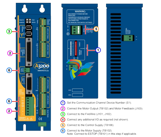
Quick Installation Guide
This chapter describes the order in which connections and settings should typically be made to the Ndrive CP. If a custom interconnection drawing was created for your system (look for a line item on your Sales Order under the heading “Integration”), that drawing can be found on your installation device.
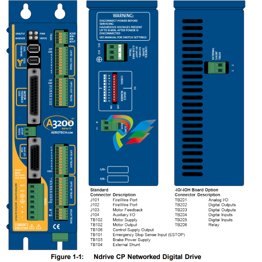
Chapter 1: Introduction
Aerotech’s Ndrive CP (Compact PWM) network digital drive is a high performance amplifier. The drive provides deterministic behavior, auto-identification, and easy software setup. The Ndrive CP’s high performance double precision floating point DSP controls the digital PID and current loops. All system configuration is done using software-settable parameters, including control loop gains and system safety functions.
The Ndrive CP is offered with an optional encoder interpolation feature (-MXU), an auxiliary square wave encoder input for dual loop control, dedicated analog and digital I/O (expandable with the -IO option), and separate power connections for motor and control supply voltages.
1.1. Drive and Software Compatibility
The following table lists the available drives and which version of the software first supported the drive. Drives that list a specific version number in the Last Software Version column will not be supported after the listed version
-
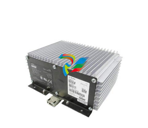
 IS200BPPBH2CAA Mark VIe Power Supply Module
 -
 IS210MACCH2AEG Motor Control and Communication Module
 -
 IS210MACCH2AGG Mark VIe Speedtronic Turbine Control Module
 -
 IS200AEPAH1AFD Printed circuit board
 -
IS200AEPAH1ACB Analog I/O Module
-
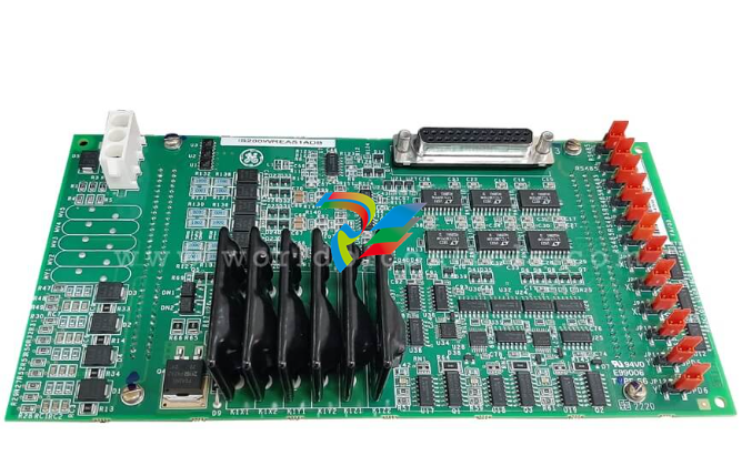 IS200WREAS1ADB AERO TRIP TB DBRD sub-board
 -
 IS200WETAH1AEC large board component made Mark VI system
 -
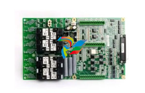
 IS200AEPAH1AHD A High-Precision Excitation Control Board for Turbine Systems
 -
 IS200WEMAH1AEA Control board
 -
 IS210MACCH1AGG processor card
 -
 IS230TNRLH1B Discrete Output Modular Assembly
 -
 Mark V Series DS200PCCAG1ACB PCB Power Connect Card
 -
 DS200SI0CG1AEA Instantaneous overcurrent card
 -
 DS200SHVMG1AGE Analog I/O board
 -
 DS200SI0CG1A6A Input/Output Module
 -
 DS200SHVMG1AFE SCR High Voltage Interface Board
 -
 DS200RT8AG3AHC Relay Output Terminal Board
 -
 DS200FSAAG1ABA PCB Field Supply Gate Amplifier Board
 -
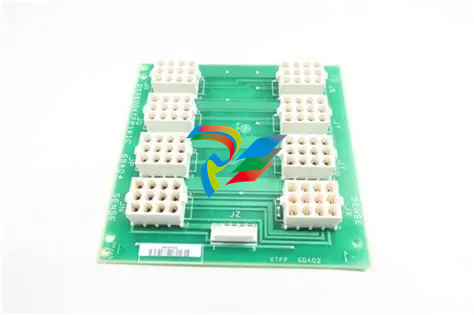
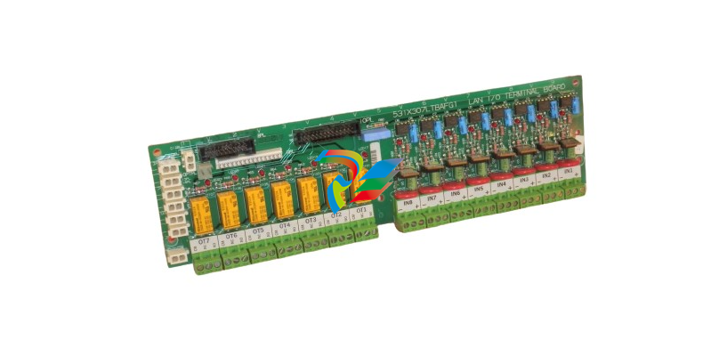 531X307LTBAFG1 F31X307LTBA LAN I/O Terminal Board
 -
 ABB AFS670 19" Ruggedized Switch AFS670-EREEDDDSSEEEEEEEPZYX05.1.0
 -
 NI Controller for VXI VXIPC-871B
 -
 IS200EPMCH1GE Mark VIe Patch Cord Power Distribution Card
 -
 VMICPCI-7632-03310 IS215UCCAH3A 350-657362-003310J GE gas turbine system control processor board
 -
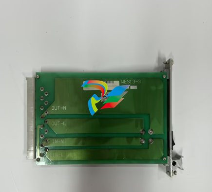 WEA13-13 2508-21001 Control Module / I/O Board
 -
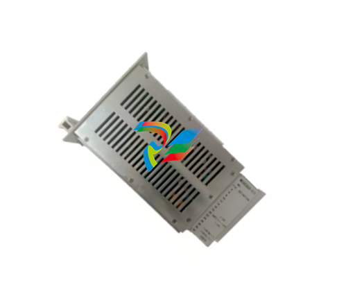
.jpg) WES5120 2340-21004 Controller Main Module
WES5120 2340-21004 Controller Main Module -
 WES5120 2340-21006 Field Controller Master Unit Module
 -
WESDAC D20ME 18-MAR-13 Excitation Control Module
-
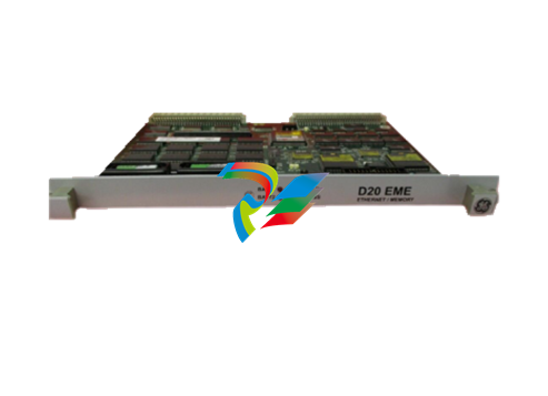
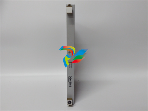 D20 EME 2400-21004 Ethernet communication and expansion module
 -
 GE DS3800XTFP1E1C Thyristor Fan Out Board Brand
 -
 GE SR745-W2-P1-G1-HI-A-L-R-E Feeder protection relay
 -
 GE IS230TNDSH2A Discrete Output Relay Module Brand
 -
 GE Fanuc IS200TDBSH2ACC Mark VI Terminal Board Brand
 -
 GE PMC-0247RC-282000 350-93750247-282000F Disk Drive
 -
GE PMC-0247RC-282000 350-93750247-282000F Disk Drive
-
 GE VMIVME-1150 Serial Communications Controller
 -
 GE VMIVME-5576 Fiber-Optic Reflective Memory with Interrupts
 -
 GE VMIC Isolated Digital Output VMIVME-2170A
 -
 GE MULTILIN 760 FEEDER MANAGEMENT RELAY 760-P5-G5-S5-HI-A20-R-E
 -
 GE IS200AEPAH1BKE IS215WEPAH2BB Printed circuit board
 -
 GE IS210BPPCH1A Mark VIe I/O Pack Processor Card
 -
 GE IS220PRTDH1A 336A4940CSP6 High-Performance RTD Input Module
 -
GE IS220PDIAH1BE 336A5026ADP4 Discrete Input Module
-
 GE IS420ESWBH3A IONET Switch Module
 -
 GE 516TX 336A4940DNP516TX 16-port Ethernet switch
 -
 GE EVMECNTM13 Embedded control module
 -
GE EVPBDP0001 EVPBDP032 control module
-
 GE Hydran M2-X Enhanced Monitoring with Extended Sensor Life
 -
 GE UR6CH Digital I/O Module
 -
 GE IC695CPU315-CD Central processing unit
 -
 GE 531X305NTBAMG1 DR Terminal Board
 -
 GE 531X305NTBALG1 NTB/3TB Terminal Board 531X Series
 -
 GE 531X305NTBAJG1 NTB/3TB Terminal Board.
 -
GE 531X305NTBAHG1 NTB/3TB Terminal Board 531X
-
 GE 531X305NTBAEG1 is a PCB that functions as a DR terminal board.
 -
General Electric 531X305NTBACG1 NTB/3TB Terminal Board 531X
-
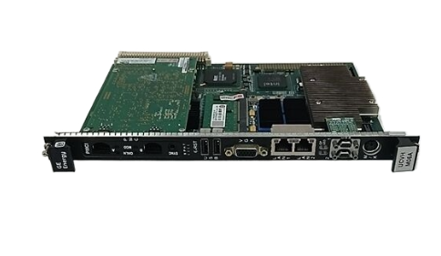
 GE Digital Energy D20 Analog Input Module
 -
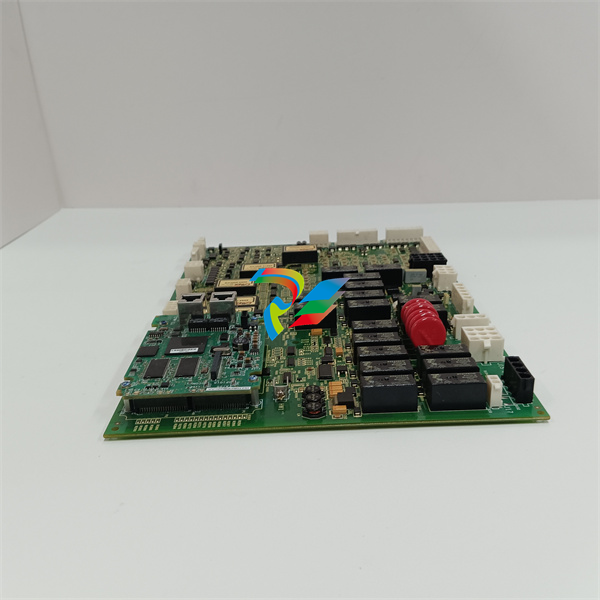
 GE 94-164136-001 main board Control board
 -
 GE 269 PLUS-D/O-100P-125V Digital motor relay
 -
 GALIL DMC-9940 High-performance motion controller
 -
FUJI NP1BS-08 base plate
-
 FUJI NP1Y32T09P1 Transistor drain type digital output module
 -
 FUJI NP1Y16R-08 Digital Output Module
 -
 FUJI NP1X3206-A High-speed digital input module
 -
 FUJI NP1AYH4I-MR current output module
 -
 FUJI NP1S-22 Power module redundancy
 -
 FUJI RPXD2150-1T servo drive module
 -
 FUJI FVR008E7S-2UX Ac frequency converter
 -
 FUJI Ac frequency converter FVR008E7S-2
 -
 FUJI FVR004G5B-2 Small general-purpose frequency converter
 -
 FUJI A50L-2001-0232 Industrial control module
 -
 FUJI A50L-001-0266#N High-performance servo amplifier
 -
 Honeywell FS7-2173-2RP Gas sensor
 -
 Honeywell 10106/2/1 Digital Input Module in Stock
 -
FRCE SYS68K CPU-40 B/16 PLC core processor module
-
 Foxboro FBM I/O cards PBCO-D8-009
 -
 Foxboro AD916AE Digital Control System (DCS) Module
 -
 GE SR750-P5-G5-S5-HI-A20-R-E Multilin Relay
 -
.jpg) FOXBORO H90 H90C9AA0117S Industrial Computer Workstation
FOXBORO H90 H90C9AA0117S Industrial Computer Workstation -
FOXBORO RH928AW | I/A Series Relay Output Module
-
.jpg) Foxboro N-2AX+DIO Multi-functional input/output module
Foxboro N-2AX+DIO Multi-functional input/output module -
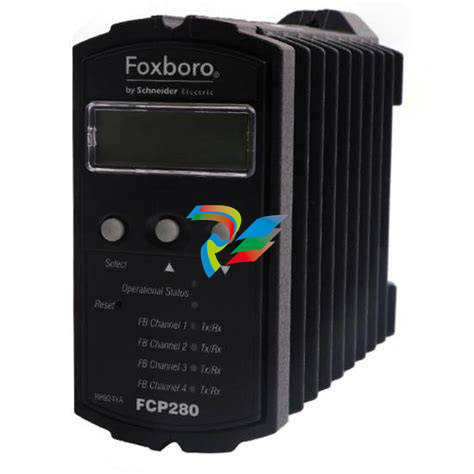 Foxboro RH924WA FCP280 Fiber Optic Network Adapter
 -
 FOXBORO H92 Versatile Hardware Component In
 -
 Foxboro FBM218 P0922VW HART® Communication Redundant Output Interface Module
 -
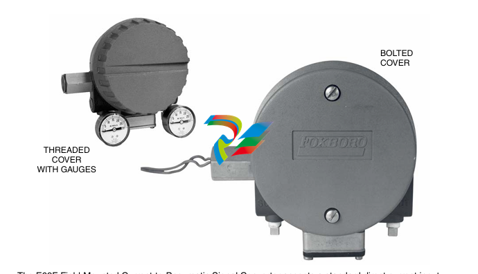
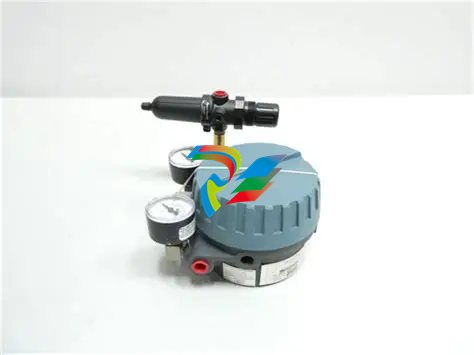
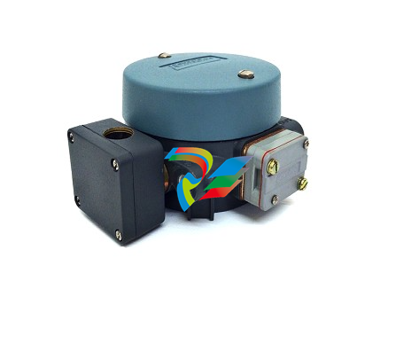 Foxboro E69F-TI2-J-R-S E69F Series Current-To-Pneumatic Signal Converter
 -
 Foxboro E69F-BI2-S Converter
 -
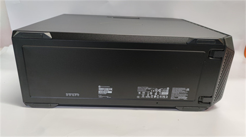
.jpg) Foxboro H92A049E0700 The host of the DCS control station
Foxboro H92A049E0700 The host of the DCS control station -
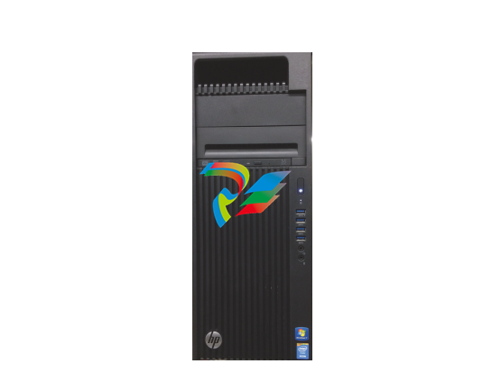
 Foxboro H90C9AA0117S Industrial computer workstation
 -
 Foxboro RH101AA High-performance industrial control module
 -
 Foxboro P0922YU FPS400-24 I/A Series Power supply
 -
.png) FOXBORO P0973LN Chassis-based managed switch with independent power supply
FOXBORO P0973LN Chassis-based managed switch with independent power supply -
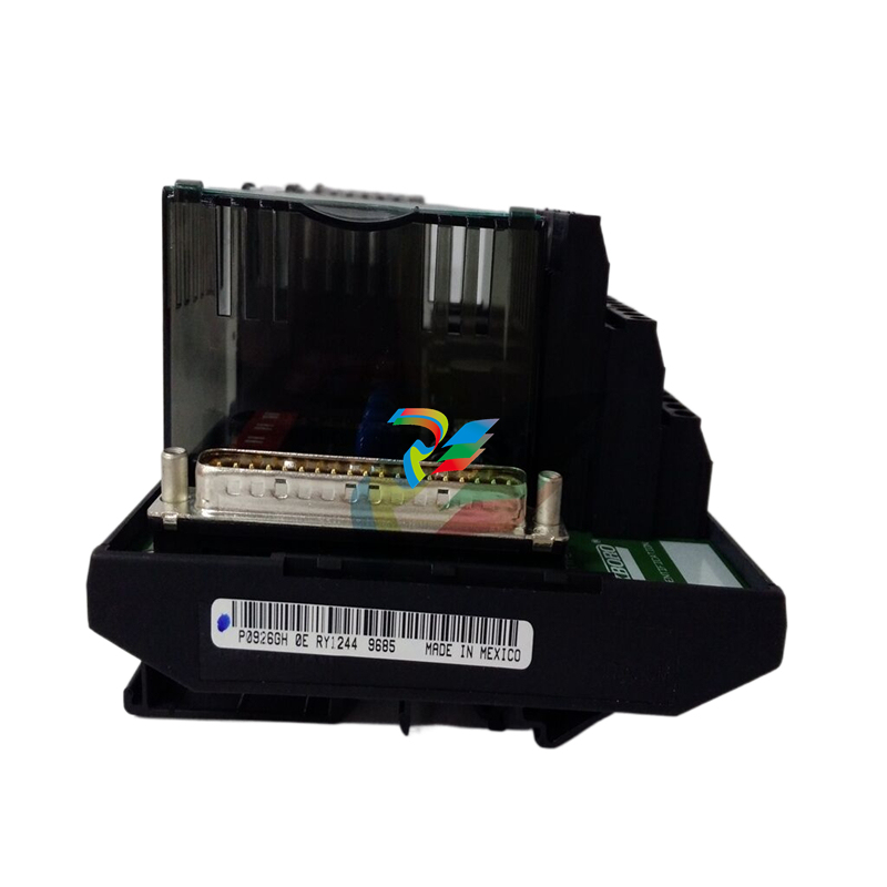
.jpg) FOXBORO P0926PA Input/output module
FOXBORO P0926PA Input/output module -
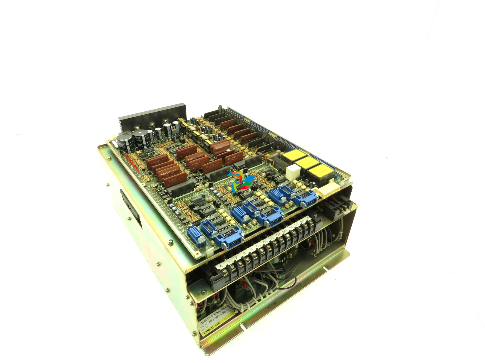 Fanuc A06B-6050-H402 3 AXIS ANALOG AC SERVO DRIVE
 -
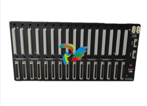
.jpg) FOXBORO L0130AD L0130AE-0H Power module group
FOXBORO L0130AD L0130AE-0H Power module group -
_lVjBYb.jpg) FOXBORO 0399085B 0303440C+0303458A Combination Control Module
FOXBORO 0399085B 0303440C+0303458A Combination Control Module -
 FOXBORO SY-0399095E (SY-0303451D+SY-0303460E) Process control board
 -
.jpg) FOXBORO 0399071D 0303440C+0303443B Input/Output (I/O) Module
FOXBORO 0399071D 0303440C+0303443B Input/Output (I/O) Module -
.jpg) FOXBORO RH924UQ Redundant Controller module
FOXBORO RH924UQ Redundant Controller module -
 FFOXBORO E69F-TI2-S current pneumatic converter
 -
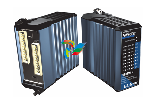 FOXBORO FBM219 RH916RH Discrete I/O Module
 -
 FOXBORO FBM227 P0927AC Module
 -
.jpg) FOXBORO 0399144 SY-0301059F SY-1025115C/SY-1025120E I/O module
FOXBORO 0399144 SY-0301059F SY-1025115C/SY-1025120E I/O module -
.jpg) FOXBORO SY-60399001R SY-60301001RB Industrial Control Module
FOXBORO SY-60399001R SY-60301001RB Industrial Control Module -
 FOXBORO 0399143 SY-0301060R SY-1025115C SY-1025120E Combined control board
 -
 FOXBORO 873EC-JIPFGZ electrodeless conductivity analyzer
 -
 FOXBORO P0916PH (High-density HART I/O Module)
 -
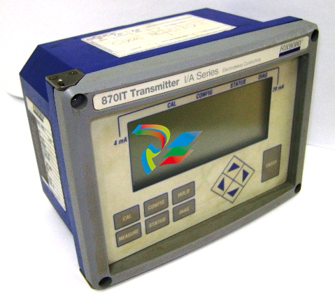 FOXBORO 870ITEC-AYFNZ-7 Intelligent Electrochemical Transmitters
 -
 FOXBORO Compact FBM240. Redundant with Readback, Discrete
 -
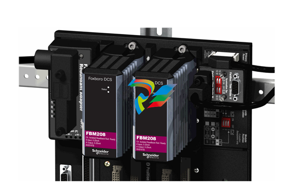 FOXBORO FBM208/b, Redundant with Readback, 0 to 20 mA I/O Module
 -
 FOXBORO FBM201e Analog Input (0 to 20 mA) Interface Modules
 -
.jpg) FOXBORO P0916WG Terminal cable
FOXBORO P0916WG Terminal cable -
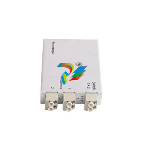 FOXBORO P0926MX 2-Port Splitter
 -
.jpg) FOXBORO AD908JQ High-Frequency Module
FOXBORO AD908JQ High-Frequency Module -
.jpg) FOXBORO AD916CC Processor module
FOXBORO AD916CC Processor module -
 Foxboro DCS FBM206 Pulse Input Module
 -
 FOXBORO FBM216 HART® Communication Redundant Input Interface Module
 -
 Foxboro p0903nu 1×8 unit sub-component module
 -
 Foxboro P0911SM Industrial control module
 -
 Foxboro CM902WM I/O module
 -
 Foxboro CM902WL Power module
 -
 Foxboro P0972VA Industrial Control Module
 -
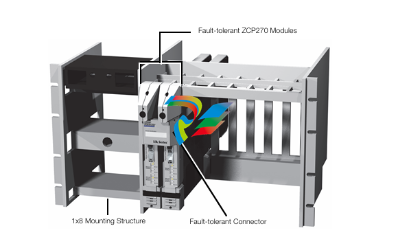
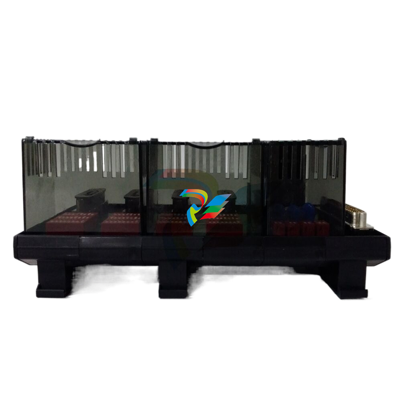
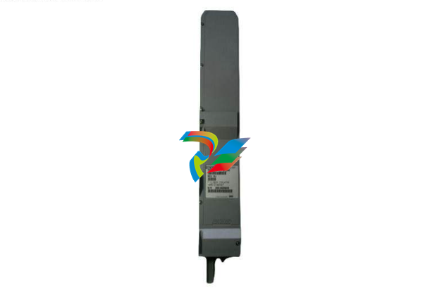
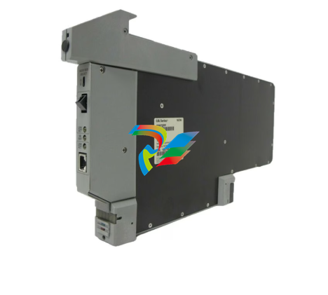
 Foxboro Z-Module Control Processor 270 (ZCP270)
 -
 Foxboro PO916JS 16-channel terminal block module
 -
 Foxboro PO911SM High-performance digital/analog input/output module
 -
 Foxboro P0972PP-NCNI Network Interface Module
 -
.jpg) FOXBORO P0971QZ controller module
FOXBORO P0971QZ controller module -
 FOXBORO P0971DP Thermal resistance input/output module
 -
 FOXBORO P0970VB Cable connector
 -
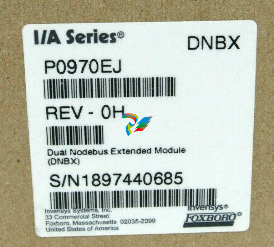 FOXBORO P0970EJ-DNBX Dual-node bus expansion module


