
SYNCHROTACT® 5 Operating Instructions SYN 5201 SYN 5202
Functional principle
2.1 Brief description
The SYNCHROTACT 5 digital synchronizer is used for automatic synchronizing and
paralleling of generators with lines and for the paralleling of already synchronous lines.
The device is designed for system frequencies of either 50/60 Hz or 16 2
/3 Hz.
SYN 5201 is a single-channel synchronizing device whose component choice and
software design provides the highest security against incorrect paralleling.
SYN 5202 consists of two independent channels with different hardware and software.
This dual-channel property maximizes security against incorrect paralleling.
All parameters required for paralleling are stored in a parameter set. The paralleling
conditions and the characteristics of the voltage and frequency matchers are defined in
this set. With the option providing seven parameter sets, paralleling can be carried out
under different conditions or with different matcher characteristics using the same
device. Seven configurable digital inputs and outputs are available for the selection and
back indication of a parameter set.
The data which are important for commissioning and for control purposes can be
uploaded or downloaded using the PC tool SynView or, alternatively, via the keypad on
Paralleling functions
The automatic paralleling process can basically be divided into four function blocks:
1. Measuring
2. Voltage and frequency matching
3. Monitoring of paralleling conditions
4. Paralleling command generation
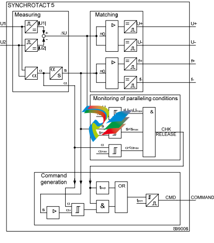
In the following figure, the block circuit diagram of the basic paralleling functions of
SYNCHROTACT 5 is simplified and shows a single-channel configuration. The
individual functions are described more precisely in the following sections.
Measuring
The following measured variables are generated from the two single-phase measuring
voltages:
Voltage U1, U2
U1 is the reference voltage e.g. line
U2 is the adjustable voltage e.g. generator.
Frequency f1, f2
f1 is the reference frequency
f2 is the adjustable frequency.
Voltage difference ΔU
ΔU = IU1I – IU2I
ΔU > 0 Adjustable voltage is lower
ΔU < 0 Adjustable voltage is higher
Slip s
%100*
1
21
f
ff s − =
s > 0 Adjustable frequency is less (e.g. generator is sub-synchronous)
s < 0 Adjustable frequency is greater (e.g. generator is oversynchronous)
Phase-angle difference α
α ϕ −= ϕ21
α > 0 Adjustable frequency is lagging
α < 0 Adjustable frequency is leading
Acceleration ds/dt
dtds [ ]ss
x
x
x /%*2/
56
1
∑
=
=
Δ=
(Every 0.5 s, an average value is formed from 56 measurements; sampling period:
9 ms)
ds/dt > 0 Adjustable frequency is reduced (e.g. generator accelerates)
ds/dt < 0 Adjustable frequency increases (e.g. generator is slowed down)
With SYN 5202, the measurement is carried out separately for each channel. It is
possible to carry out three-phase measurements in order to detect connection faults
(rotary field, polarity) and losses of phase.
Voltage measurement (SYN 5202: channel 1)
The two input voltages U1 and U2 are passed to the processor via high-impedance input
resistors, differential amplifiers, low-pass filters and A/D converters.
Voltage measurement channel 2 (SYN 5202 only)
The two input voltages U1 and U2 are passed through high-impedance input resistors
and differential amplifiers. The signal for the amplitude value is formed from this by
conversion and filtering . For zero-passage detection, the signal is filtered and passed
through a comparator. The signals prepared in this way are passed to the processor via
the A/D converter
Voltage and frequency matching
Working range of the voltage matcher
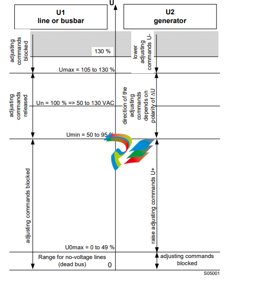
If the voltage U1 is in the range between Umin and Umax and the voltage U2 is greater
than U0max the adjusting commands are released. The direction of the adjusting
commands depends on the polarity of ΔU.
As an additional condition, both frequencies must be in the range fn±5 Hz.
Voltage matcher with variable pulse times
The voltage matcher issues a command the length of which is proportional to the current
voltage difference. The proportionality factor dU/dt can be adapted to the voltage
regulator. The voltage matcher aims at a value in the middle of the set tolerance band.
The adjusting command length tp U is:
dtdU
U U
U
tpU /
2
max max
⎟
⎟
⎠
⎞
⎜
⎜
⎝
⎛ Δ−−Δ+
−Δ
=
The adjusting pulse is discontinued as soon as the voltage difference passes through
the target value. The command length does not fall below a settable minimum value.
After an adjusting command, the system waits for the set pulse interval ts U so that the
actual values can stabilise to the new setpoint.
Voltage matching with variable intervals
The function INVERSE U changes the way the voltage matcher functions. The pulses
are now always the same length, but the intervals are inversely proportional to the
-
 Beckhoff CX5130-0160 CPU module
 -
Beckhoff CX5130-0155 CPU module
-
 Beckhoff CX5130-0150 CPU module
 -
Beckhoff CX5130-0143 CPU module
-
 Beckhoff CX5130-0142 CPU module
 -
Beckhoff CX5130-0140 CPU module
-
Beckhoff CX5130-0135 CPU module
-
Beckhoff CX5130-0130 CPU module
-
Beckhoff CX5130-0125 CPU module
-
 Beckhoff CX5130-0123 CPU module
 -
Beckhoff CX5130-0122 CPU module
-
Beckhoff CX5130-0121 CPU module
-
 Beckhoff CX5130-0115 CPU module
 -
Beckhoff CX5130-0113 CPU module
-
Beckhoff CX5130-0112 CPU module
-
Beckhoff CX5130-0111 CPU module
-
Beckhoff CX5130-0110 CPU module, Microsoft Windows Embedded Compact 7. no TwinCAT
-
Beckhoff CX5130-0100 CPU module, no operating system, no TwinCAT
-
 DEIF FAS-113DG Synchronisation & circuit breaker closing
 -
 DEIF FAS-115DG Synchronisation & circuit breaker closing
 -
 DEIF HAS-111DG Synchronisation & circuit breaker closing
 -
 DEIF LSU-122DG Load sharing, paralleling & operation
 -
 DEIF LSU-114DG Load sharing, paralleling & operation
 -
 DEIF LSU-113DG Load sharing, paralleling & operation
 -
 DEIF LSU-112DG Load sharing, paralleling & operation
 -
 DEIF RMF-112D Frequency relay
 -
 DEIF RMC-142D Current relay
 -
 DEIF RMC-132D Current relay
 -
 DEIF RMC-131D Current relay
 -
 DEIF RMC-122D Current relay
 -
 DEIF RMC-121D Current relay
 -
 DEIF RMC-111D Current relay
 -
 DEIF MVR-V211 Busbar Protection
 -
 DEIF MVR-T257 Transformer Differential Protection
 -
 DEIF MVR-T256 Transformer Differential Protection
 -
 DEIF MVR-T216 Transformer Differential Protection
 -
DEIF MVR-T215 Transformer Protection
-
 DEIF MVR-M257 Motor Differential Protection
 -
 DEIF MVR-M255 Motor Protection
 -
 DEIF MVR-M215 Motor Protection
 -
 DEIF MVR-M210 Motor Protection
 -
 DEIF MVR-G257 Generator Differential Protection
 -
 DEIF MVR-G215 Generator Protection
 -
 DEIF MVR-F255 Directional Feeder Protection
 -
 DEIF MVR-F215 Directional Feeder Protection
 -
DEIF MVR-F210 Feeder Protection
-
 DEIF MVR-F205 Directional Feeder Protection
 -
 DEIF MVR-F201 Basic Feeder Protection
 -
DEIF MVR-200 series Medium Voltage Relay
-
 DEIF MDR-2 Multi-differential relay
 -
 DEIF LMR-122D Loss of mains relay
 -
 DEIF LMR-111D Loss of mains relay
 -
 DEIF APU-4 Advanced G59 and G99 protection unit
 -
 DEIF iE 650 PLC - The most robust programmable automation controller available
 -
 DEIF iE 350 PLC - Programmable Automation PLC Controller
 -
 DEIF iE 250 PLC Versatile and modular intelligent energy PLC controller
 -
 DEIF PPM-3 EDG Protection and Power Management
 -
 DEIF AGC 3X 4198000234E AUTOMATIC GENSET CONTROLLER
 -
 SAUTER ASF123 Damper actuator with spring return
 -
SAUTER ASF122 Damper actuator with spring return
-
SAUTER ASF113F122 Damper actuator with spring return
-
SAUTER ASF113F120 Damper actuator with spring return
-
SAUTER ASF112F122 Damper actuator with spring return
-
SAUTER ASF112F120 Damper actuator with spring return
-
 SAUTER ASM 124/134 series - ASM134F130 Damper actuator
 -
SAUTER ASM 134 series - ASM134SF132 Damper actuator
-
SAUTER ASM 124/134 series - ASM124SF132 Damper actuator
-
SAUTER ASM 124/134 series - ASM124F122 Damper actuator
-
SAUTER ASM 124/134 series - ASM124F120 Damper actuator
-
 SAUTER Valve actuator ASM 105S/115S series ASM115SF152
 -
SAUTER Valve actuator ASM 105S/115S series ASM105SF152
-
SAUTER Valve actuator ASM 105S/115S series ASM115SF132
-
SAUTER Valve actuator ASM 105/115 series ASM105SF132
-
 SAUTER Valve actuator ASM 105/115 series ASM115F122
 -
SAUTER Valve actuator ASM 105/115 series ASM115F120
-
SAUTER Valve actuator ASM 105/115 series ASM105F122
-
SAUTER Valve actuator ASM 105/115 series ASM105F120
-
SAUTER Valve actuator ASM 105/115 series ASM105F10
-
 SAUTER AKF113S Rotating actuator AKF 112/113 series
 -
SAUTER AKF113F122 Rotating actuator AKF 112/113 series
-
SAUTER AKF113F120 Rotating actuator AKF 112/113 series
-
SAUTER AKF112F122 Rotating actuator AKF 112/113 series
-
SAUTER AKF112F120 Rotating actuator AKF 112/113 series
-
 SAUTER AKM115SAF332: Smart Actuator for ball valve, BACnet/IP
 -
 SAUTER AKM115SAF232 Rotating Actuator AKM 115SA Smart Actuator
 -
 SAUTER AKM115SF152 Rotating Actuator AKM 105S/115S Series
 -
SAUTER AKM115SF132 Rotating Actuator AKM 105S/115S Series
-
SAUTER AKM105SF132 Rotating Actuator AKM 105S/115S Series
-
 SAUTER AKM115F122 Rotating actuator AKM 105/115 series
 -
 SAUTER Rotating actuator AKM 105/115 series AKM115F120
 -
SAUTER Rotating actuator AKM 105/115 series AKM105F122
-
SAUTER Rotating actuator AKM 105/115 series AKM105F120
-
 SAUTER Continuous actuator for unit valves, with stroke AXS215S
 -
 SAUTER Linear valve actuator AXT/AXS series AXT211
 -
SAUTER Linear valve actuator AXT/AXS series AXT201
-
 SAUTER Linear valve actuator AXM/AXF series AXF217S
 -
SAUTER Linear valve actuator AXM/AXF series AXM217S
-
SAUTER AXM217SF404 is an electric actuator for unit valves.
-
SAUTER AXM217SF402 is an electric actuator for unit valves.
-
SAUTER Linear valve actuator AXM/AXF series AXM217
-
 SAUTER Linear valve actuator AVF 124/125 series AVF125S
 -
SAUTER Linear valve actuator AVF 124/125 series AVF124S
-
SAUTER Linear valve actuator AVF 124/125 series AVF124S
-
 SAUTER AVM322S-R Linear valve actuator AVM 234S series
 -
SAUTER AVM322-R Linear valve actuator AVM 234S series
-
SAUTER AVM322SF132 Linear valve actuator AVM 234S series
-
 SAUTER AVM321SF132 Linear Valve Actuator
 -
 GE Power Conversion P112-6053 Advanced Micro Controller (AMC2)
 -
GE Power Conversion P111-6053 Advanced Micro Controller (AMC2)
-
 GE Power Conversion P110-6053 Advanced Micro Controller (AMC2)
 -
 GE Power Conversion P122-6052 Advanced Micro Controller (AMC2)
 -
GE Power Conversion P121-6052 Advanced Micro Controller (AMC2)
-
 GE Power Conversion P112-6152 Advanced Micro Controller (AMC2)
 -
GE Power Conversion P110-6152 Advanced Micro Controller (AMC2)
-
GE Power Conversion P112-6052 Advanced Micro Controller (AMC2)
-
GE P106-6052 AMC2 Advanced Micro Controller Unit
-
SAUTER AVF234SF232 Linear valve actuator AVM 234S series
-
SAUTER AVF234SF132 Linear valve actuator AVM 234S series
-
 SAUTER Linear valve actuator AVM 234S series AVM234SF132-6
 -
SAUTER Linear valve actuator AVM 234S series AVM234SF132-5
-
SAUTER Linear valve actuator AVM 234S series AVM234SF132
-
SAUTER Linear valve actuator AVM215SF132-7
-
SAUTER Linear valve actuator AVM215SF132R
-
 Linear valve actuator AVM 115SA Smart Actuator AVM115SAF332
 -
Linear valve actuator AVM 115SA Smart Actuator AVM115SAF232
-
 SAUTER Linear valve actuator AVM 105S/115S series AVM115SF132
 -
SAUTER Linear valve actuator AVM 105S/115S series AVM105SF132
-
 SAUTER AVM115F901 Linear Valve Actuator



