
DOOSANDOOSAN AC SERVO MOTOR/DRIVE VISION DVSC - TM Series
Installation and wiring
1.1. Designations
Designations of DOOSAN AC Servo Motor and Drive are as follows.
Please refer to this section for system installation and after service.
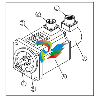
1)Encoder Connector 2)Power Connector 3)Name Plate 4)Shaft 5 )Flange 6 )Frame 7 )Encoder
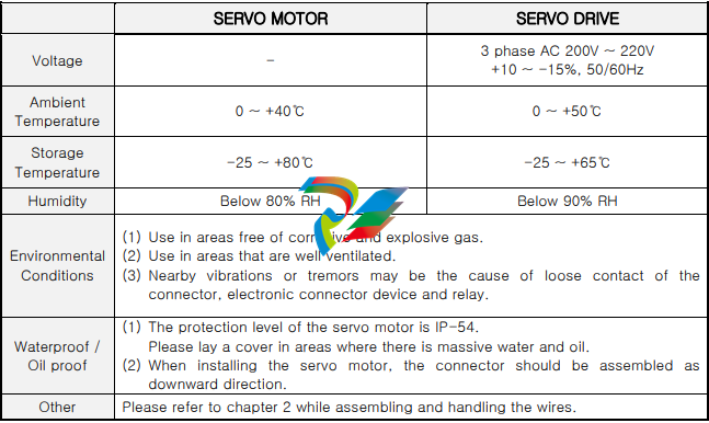
1.2. Environmental conditions
This product was designed for indoor usage.
Caution : If used in different circumstances and environment other than stated below, damages
may occur.
Please use under the following conditions.
1.3. Installation method
1.3.1. Assembling of the servo motor
▷ Warning: While assembling the servo motor, avoid dropping it.
▷ Caution: While mounting the servo motor horizontally, the connector should be assembled
facing downward.
▷ The servo motor can be mounted horizontally or vertically.
▷ To prevent vibrations and extend the life of coupling and bearing, the motor shaft and the loading
shaft should be precisely aligned. Use flexible coupling when connecting directly to the load.
① The outer part of the coupling should be measured at four equidistant points each 90˚ apart,
and the gap between the maximum and the minimum readings should not exceed 0.03㎜.
② The center point of the motor and the loading shaft should be precisely aligned.
▷ Avoid excessive radial and thrust load to the motor shaft and also avoid impact that is more
than 10G when mounting the gear, coupling, pulley and etc. at the same time.
▷ A minus load means continuous operation in the regenerative braking state, when the motor is
rotated by load. The regenerative braking capacity of the servo drive is short term rated
specification equivalent to stop time of the motor. Thus, it should not be used in minus load that
generates continuous regenerative braking.
ex) Servo system for descending objects(without counterweight)
▷ The admissible load inertia into the motor shaft is within 5 times than the inertia of applied servo
motor. If it exceeds this, during deceleration it may cause regenerative malfunction.
The following steps should be taken if the load inertia exceeds more than 5 times the inertia of
the servo motor.
- Reduce the current limit. – Decelerate slowly.(Slow Down)
- Lower the maximum speed in use.
1.3.2. Mounting of the servo drive
▷ Warning: To prevent electric shock, turn off the power while mounting or uninstalling.
▷ While installing the panel, the size of the panel, cooling and wiring should be considered in
order to maintain a difference of temperature below 5℃ between the panel temperature and the
surrounding temperature in accordance with heat value of the equipment and box size.
▷ If a heating element is placed nearby, the surrounding temperature of the servo drive should be
maintained below 55℃ at all cases despite temperature rise by convection and radiation. Use a
fan to ventilate sealed inner air, and proper ventilation should be used for convection of the air.
▷ If a vibrating element is placed nearby, the drive should be mounted on shock absorbing surface.
▷ If the servo drive be exposed to corrosive gas for a long time, may cause damages to connecting
devices such as relay and circuit breaker, thus it should be avoided.
▷ Environmental conditions such as high temperature, high humidity, excessive dust and metal
particles should be avoided.
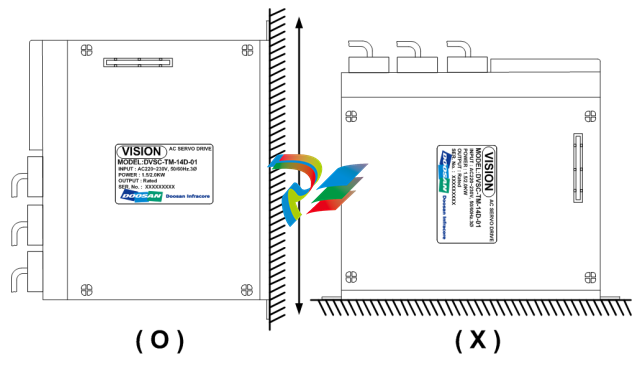
◆ Mounting method
▷ There should be a space wider than 100㎜ below and above the servo drive.
▷ There should be a space wider than 30㎜ on both sides of the servo drive.
▷ Mount the servo drive vertically. Do not use if it is mounted horizontally.
1.4. Wiring
▶ For signal lines and encoder lines, use twisted lines or multi-core shielded twisted-pair lines.
The length for command input lines should be maximum 3m, and the encoder line should be
maximum 10m or less.
Wiring must be done in shortest distance and the remaining length should be cut.
▶ The ground circuit should be a thick line. Usage of third-class grounding or above (ground
resistance 100Ω or less) is recommended. Also, make sure to ground at one-point grounding.
▶ The following precautions should be taken to avoid malfunction due to noise.
- The noise filter should be placed as near as possible.
- Mount a surge absorber to the coil of the relay, electromagnetic contacts, solenoids and etc.
- The power line (AC input, motor input line) and the signal line should be placed 30㎝ apart
or more. Do not put them into the same duct or tie them in a bundle.
- If the power source of the servo drive is used in common with an electric welder or electrical
discharge machine, or a high-frequency noise source is present, attach noise filter to the
power or the input circuits.
- Since the core wire of the signal line cable is as thin as only 0.2 ~ 0.3㎟, excessive force to the
line should be avoided to prevent damages.
1.5. Noise treatment
For wiring and grounding of the servo drive, the effect of switching noise which is generated by the
built-in IPM should be reduced as much as possible. Unexpected effect by outside noise should be
reduced as much as possible.
▶ Grounding method
The servo drive supplies power to the motor according to the switching of the IPM device.
Thus the Cf dv/dt current flows from the power component to the floating capacity of the motor.
To prevent the effect of the switching noise, the motor frame terminal should be connected to
the PE terminal of the servo drive terminal block and the PE terminal of the servo drive should be
directly grounded to standard ground panel.
▶ Noise filter
Noise filter is used in order to prevent noise from the power line. Please refer to the following
conditions while installing.
(a) Separate the input and output wiring and do not tie them together or put them into the same
duct.
(b) Do not put the ground wire into the same duct with the filter output line or other signal lines.
And do not tie them together.
(c) The ground wire should be wired singly to the ground panel.
(d) If the unit contains the filter, connect the filter and the equipment ground to the base of the
unit.
2. Operation
2.1. Automatic operation
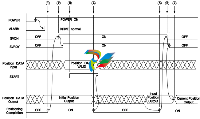
① If the drive maintains a normal state (takes 5 sec) after the POWER turns on, it outputs the initial
position data and the positioning completion signal(VPF) after it detects the initial position by the
absolute encoder.
② When the SVON signal is ON, the SVRDY signal turns ON after the inner GATE turns ON.
③ When the START signal is ON, the servo motor will rotate according to the position data.
(Maintain ON state of the START signal for about 100 ~ 200 msec.)
④ When the position movement starts, the position data 0 will be outputted with turning OFF the
VPF(Positioning Completion) signal.
⑤ When the position movement is complete, the VPF signal turns ON after the position input data is
outputted.
⑥ The host controller must turn OFF the SVON signal only after the VPF signal turns ON.
(Move to the next position after the SVRDY signal turns OFF.)
⑦ After the SVRDY and the SVON signals are turned OFF, the current position data is outputted.
2.2. Jog operation and Usage of BRAKE Signal(Magazine Port move by the jog signal)
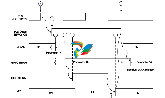
① Turn ON the Jog Switch.
② The PLC outputs the SERVO ON signal to the servo drive.
③ When the SERVO ON signal turns ON, the BRAKE release signal is outputted after the time value in
the parameter 14.
④ After the time value in the parameter 13, the SERVO READY signal is outputted.
⑤ After the SERVO READY signal is outputted, the PLC must input the JOG+ signal to the servo drive.
⑥ When the position movement is complete, the positioning completion signal(VPF) turns ON after
the position data that is increased by more than one from the previous position is outputted.
⑦ When the positioning completion signal(VPF) turns ON, the PLC turns OFF the SERVO ON signal.
Then, the servo drive turns ON the BRAKE signal and turns OFF the SERVO READY signal after the
time value in the parameter 15.
The servo drive outputs the current position data after the SERVO ON signal turns OFF.
※ In the jog mode, the motor cannot rotate over 4,000 revolutions continuously. If there is an input
over 4,000 revolutions, the motor will stop and it will not rotate. In this case, turn off the JOG+ or
JOG- signal and then turn it on again.
2.3. Parameter and Machine Origin setting method after replacement of the servo drive
At the time of the first machine assembly, it should be set the absolute encoder zero-point to the
Machine Origin. The setting method is as follows.
(These steps should be done when the external SERVO ON signal is OFF.)
2.3.1. Parameter and Machine Origin setting method of Turret/Magazine
1) Turn on the drive power.
2) Clamp the Turret.
3) Set value of the parameter 45, servo drive function selection parameter, as 0.
Please change the parameter 45 as 1 only when it needs to set as ATC because default value is 0,
Turret/Magazine. Turn the drive power OFF and then turn ON again after setting the value.
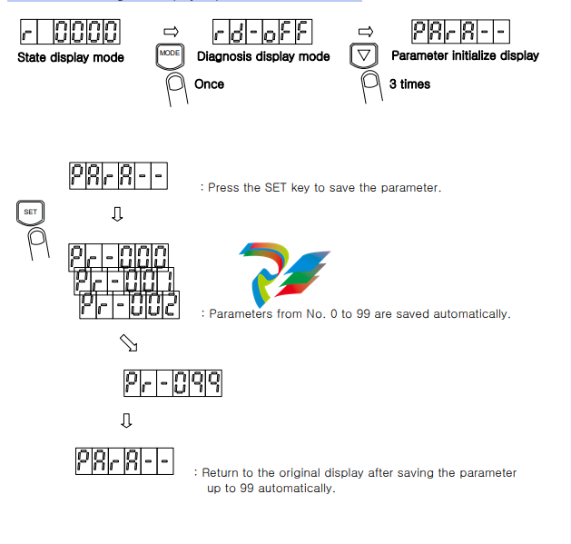
4) Initialize the parameter value.
Press the MODE key to change the display to diagnosis mode, and then press the DOWN key
three times to change the display to parameter initialize mode.
Even if an alarm occurs, it’s possible to change the display as state display mode, diagnosis display
mode, parameter setting mode, origin setting mode and alarm history display mode since version
DVSC-TM-14D-02. Also, even at alarm state, parameter or offset value setting is possible since that
version.
▶ Method of releasing the alarm state
: Once the cause of the alarm is resolved, it is possible to operate the drive by turning the power
OFF and ON again.
▶ Detection time of over load
: The operation time of the over load alarm detect circuit is as listed below.
300% ~ ; 5.5sec
275% ~ ; 6.5sec
225% ~ ; 8sec
200% ~ ; 10sec
170% ~ ; 14sec
150% ~ ; 17.5sec
140% ~ ; 20sec
130% ~ ; 25sec
120% ~ ; 30sec
3.6.3. Detailed explanation of user parameter
□0 Motor output capacity
As selection parameter of the applied motor capacity, it’s possible to select 0.8, 1.5, 1.7, 2.0, 2.3,
3.0 and 4.0kW.
0 : 1.5kW 8 : 0.8kW 17 : 1.7kW 20 : 2.0kW 23 : 2.3kW 30 : 3.0kW 40 : 4.0kW
※ Use 14A drive for motors under 3.0kW and 28A drive for motors more than 3.0kW. If not applied
properly, it may cause malfunction of the motor.
□1 Motor rotation direction
This parameter sets the rotation direction of the motor. Please select according to the structure
of the equipment.
0 : Selects when the rotation direction of the motor and the equipment is the same.
1 : Selects when the rotation direction of the motor and the equipment is different.
□2 Option function
This parameter is used when the NC uses the drive itself JOG mode or sets the origin position.
For use this function, OVR0 and OVR1 contact points must be connected between the drive and
the NC, and the NC program should support this feature.
0 : Option disable 1 : Option enable
OVR0 OVR1 function
OFF ON The operation mode will be changed as the drive itself JOG, and the motor
rotates by JOG+, JOG- signals.
ON ON Machine origin setting will be executed.
□3 Direction fixing, JOG function selection
This parameter defines the function of JOG+(no.20) and JOG-(no.23) signals of CN1 connector.
0 : Defined as direction fixing signal.
JOG+ JOG- Rotation direction
OFF OFF Detects the shortest distance and rotates.
OFF ON The motor always rotates in clockwise.
ON OFF The motor always rotates in counterclockwise.
ON ON The motor always rotates in counterclockwise.
* The above statement is applicable if the parameter 1 is set as 0. If the parameter is set as
1, the motor rotates the opposite way.
1 : Magazine JOG operation signal (This is used when it need to move the tool post by the
JOG signal at the Magazine.)
JOG+ JOG- Contents
OFF OFF Only operates by position data input.
OFF ON Step JOG operates towards the direction the POST number decreases.
ON OFF Step JOG operates towards the direction the POST number increases.
ON ON Cannot be defined.
* The above statement is applicable if the parameter 1 is set as 0. If the parameter is set as
1, the motor rotates the opposite way. And, the position data input will be ignored if JOG+
and JOG- signals are ON.
※ For more detailed explanation, refer to ‘JOG operation’ section.
□4 Encoder pulse per 1 rotation
This parameter displays 1/4 value of encoder pulse count per rotation.
□5 Maximum POST number
This parameter sets the maximum POST number. If parameter 46 is set as 3, it’s possible to set as
maximum 255. At the Teaching mode, it’s available up to 99. The position data input exceeding the
setting number will be ignored.
Setting range : 2 ~ 127 or 255 Teaching function : 2 ~ 99
□6 Gear ratio of motor side
This parameter sets the motor rotation counts until the machine moves up to the POST set in the
parameter 7.
Setting range : 1 ~ 9999
□7 Gear ratio of machine side
This parameter sets the POST number variation until the motor rotates up to the setting data in
the parameter 6.
Setting range : 1 ~ 9999
Example)
1. At the TC model, the turret has 10 POST(10 angle) and makes 1 revolutions until the motor
makes 30.75 revolutions. In case the reduction gear ratio is determined like this, the parameter
will be set as follow, because 1 revolution of turret corresponds with 10 POST move.
Maximum POST number : 10
Gear ratio of motor side : 3075
Gear ratio of machine side : 1000
2. At the MC model, the Magazine has 41 POST(41 POT) and moves 9 POSTs until the motor
makes 101 revolutions. In case the reduction gear ratio is determined like this, the parameter will
be set as follows.
Maximum POST number : 41
Gear ratio of motor side : 101
Gear ratio of machine side : 9
□8 POST number of origin
When setting the origin of machine, input the POST number that will be set as origin into this
parameter. If parameter 46 is set as 3, it’s possible to set as maximum 255.
Please refer to ‘Machine origin setting’ for more detailed explanation.
Setting range : 1 ~ 127 or 255
□9 24 angle alternate angle function selection
This parameter sets the 24 angle alternate angle function of the Turret.
0 : Alternate angle function disable
1 : Alternate angle function enable
10 Position loop proportional gain
The proportional gain of the position loop is the parameter which determines the response of
position control loop. If the value increases, the mechanical response gets better. However,
mechanical impact on the machine may occur when the motor starts or stops. If the value
decreases, the mechanical response will get worse and position error increases by remaining pulse.
This also relates with the speed loop gain.
Setting range : 0 ~ 9999
□11 Speed loop proportional gain
The proportional gain of speed loop is the parameter which determines the response of the speed
control loop. As external characteristics, it determines the degree of rigidity. If the value of the
proportional gain increases, the rigidity becomes better. Thus the larger the setting value is the
better, but too large setting may cause oscillations and hunting. The value should be set as large
as possible under a stable condition.
Setting range : 0 ~ 9999
□12 Speed loop integral gain
The integral gain of the speed loop is a compensatory factor which reduces normal state error and
increases rigidity. If the value of integral gain is increased, the rigidity will get better. But too large
setting may cause oscillations and the system may become unstable.
Setting range : 0 ~ 9999
□13 SERVO READY ON delay time
This parameter sets the Servo Ready signal delay time to change as ON.
Setting range : 0 ~ 1000 [x 10msec]
□14 Brake OFF control delay time
In case the motor has an inner brake, this parameter sets brake release delay time.
Setting range : 0 ~ 1000 [x 10msec]
□15 Brake ON delay time
In case the motor has an inner brake, this parameter sets the time it takes for braking.
Set the value higher than actual time it takes for braking.
Setting range : 0 ~ 1000 [x 10msec]
□16 ~ □17 Reserved
□18 Positioning complete range
At position control, this parameter sets the positioning completion range. If the deviation between
the targeted position and the current position is within the setting range, the VPF terminal (no. 16
of the CN1 connector) will be turned ON. The numerical value unit means the encoder pulse and it
is 8192 pulse per rotation of the motor.
19 Remaining pulse allowable range
In position control, in each position control loop the difference between position command
and position feedback is accumulated. If this difference value exceeds the setting value, the
position deviation excess alarm will be occurred. The numerical value unit means the encoder
pulse and presently it is 8192 pulse per 1 rotation.
Setting range : 1 ~ 6000 [x 100pulse]
□20 Deceleration time after stop signal
This parameter sets the deceleration time from rotation state until the motor stops. When the
setting value is 0 as default, the motor under 3kW capacity will be stopped as 100 msec
deceleration time. And the motor more than 3kW will be stopped as 340 msec.
Setting range : 0 ~ 5000 [msec]
□21 S-shaped acceleration/deceleration time constant
This parameter sets the time constant to reduce the impact at the time of acceleration or
deceleration.
Total acceleration time : acceleration time(parameter 29) + S-shaped acceleration/deceleration
time constant
Total deceleration time : deceleration time(parameter 30) + S-shaped acceleration/deceleration
time constant
Setting range : 0 ~ 400 [msec]
□22 Positive torque limit 1
This parameter limits the torque output of the positive (+) polarity in areas except of positioning
complete range. If the value is set at 0%, positive torque will not occur. If the value is set too low,
hunting may occur when the motor starts or stops.
Setting range : 0 ~ 300 [%]
□23 Negative torque limit 1
This parameter limits the torque output of the negative (-) polarity in areas except of positioning
complete range. If the value is set at 0%, negative torque will not occur. If the value is set too low,
hunting may occur when the motor starts or stops.
Setting range : 0 ~ 300 [%]
□24 Positive torque limit 2
This parameter limits the torque output of the positive (+) polarity in areas within positioning
complete range. In purpose of applying continuous load with ON state of SVON signal after
positioning completion, the overstrain on the equipment or the motor can be avoided by setting a
low value.
25 Negative torque limit 2
This parameter limits the torque output of the negative (-) polarity in areas within positioning
complete range. In purpose of applying continuous load with ON state of SVON signal after
positioning completion, the overstrain on the equipment or the motor can be avoided by setting a
low value.
Setting range : 0 ~ 300 [%]
□26 Speed limit
This parameter limits the maximum rotation speed. Even when overshooting and such cases occur
while accelerating, the rotation speed will be limited within the setting value. Set the value at least
50rpm more than the setting value of parameter 28(rotation speed).
Setting range : 0 ~ 3000 [rpm]
□27 Jog speed at origin setting
This parameter sets the motor speed of the internal jog operation.(At Magazine, the speed of the
jog operation will be applied as the setting speed of parameter 28.)
Setting range : 1 ~ 3000 [rpm]
□28 Operation speed
This parameter sets the motor rotation speed for automatic operation or jog operation speed of the
Magazine.
Setting range : 10 ~ 3000 [rpm]
□29 Acceleration time
This parameter sets the time that takes to get to the setting speed of parameter 28 from 0 speed.
If the value is set too low, speed overshooting may occur when accelerating.
Setting range : 0 ~ 9999 [msec]
□30 Deceleration time
This parameter sets the time that takes to get to 0 speed from the setting speed of parameter 28.
If the value is set too low, positioning completion time may be delayed due to hunting when the
motor stops.
Setting range : 0 ~ 9999 [msec]
□31 Teaching function
To use the Teaching function, set this parameter as 1. It’s possible to set the movement distance
unequally unlike existing gear ratio setting method.
3000 : gear ratio setting method
1 : Teaching function enabled
□32 High torque IPM motor selection
If the high torque IPM motor is applied, set the value of this parameter as 1.
1500 : Normal SPM motor
1 : High torque IPM motor
□33 Initial state display
This parameter sets the initial display mode just after the power is ON.
Set value Initial display contents Set value Initial display contents
00 Motor rotation speed 06 Accumulated value of remaining pulse
01 Current POST number 07 Reserved
02 Absolute encoder rotation count 08 Reserved
03 Absolute encoder-one rotation 09 Alarm display
04 Effective load factor 10 Motor rotation speed
05 Maximum load factor
□34 ~ □44 Automatic setting parameters or maker parameters for management
These parameters are maker parameters for management or will be set automatically while setting
the machine origin-point.
Please do not set according to the user’s purpose. It may cause malfunction of the servo drive.
□45 Servo drive function selection
Please set this parameter first before parameter initialization or parameter setting, because this
parameter sets the servo drive function as Turret/Magazine or ATC.
Set value Function
0 Turret/Magazine
1 ATC
※ For normal operation of the servo drive, the drive power must be turned OFF and ON again,
after setting parameter 45.
□46 Option function
This parameter sets up OVERRIDE, selective application of offset and 255 TOOL function.
For use the OVERRIDE function OVR0, OVR1, OVR2 and OVR3 contact points must be connected
between the drive and the NC, and the NC program should support this feature.
For use the function of selective application of offset value, OVR0 and AUX_OUT0 contact points
must be connected between the drive and the NC, and the NC program should support this feature.
For use of 255 TOOL function, OVR0 and AUX_OUT0 contact points must be connected between
the drive and the NC, and the NC program should support this feature.
0 : Option function disabled
1 : OVERRIDE function enabled
2 : Selective application of offset value
3 : 255 TOOL function enabled
51 Tool number decrease direction Backlash
This parameter sets the Backlash compensation value for tool number decrease direction. If this
parameter is set as 0, Backlash compensation value is not applied. The numerical value unit means
the encoder pulse and presently it is 8192 pulse per 1 rotation.
Please refer to ‘Example of tool number increase direction Backlash compensation value setting’
for more detailed setting method.
Setting range : 0 ~ 9999[PULSE]
□52 Speed Command Filter
This parameter sets Speed Command Filter value. If this parameter is set as 0, Speed Command
Filter value is not applied.
Setting range : 0 ~ 9999[Hz]
□53 Speed Feedback Filter
This parameter sets Speed Feedback Filter value. If this parameter is set as 0, Speed Feedback
Filter value is not applied.
Setting range : 0 ~ 9999[Hz]
□54 Current Command Filter
This parameter sets Current Command Filter value. If this parameter is set as 0, Current Command
Filter value is not applied.
Setting range : 0 ~ 9999[Hz]
□55 Current Feedback Filter
This parameter sets Current Feedback Filter value. If this parameter is set as 0, Current Feedback
Filter value is not applied.
Setting range : 0 ~ 9999[Hz]
□56 Position Signal Output Function
Set this parameter as 1 to use position signal output function. Use this function when it needs to
output the position signal using the existing tool number output contact point at the specific
position(angle) that is set by user. And this function is available only if the NC is ready for this
feature.
0 : disabled
1 : Position signal output function enabled
-
 Beckhoff C6640-0040 Control Cabinet Industrial PC 7-Slot
 -
 BECKHOFF CONTROL CABINET INDUSTRIAL PC - C6930-1062-0050
 -
 Beckhoff Automation EtherCAT Terminal EK1100 EK1122
 -
 Beckhoff CP6533-0001-0060 IPC
 -
 Beckhoff EK9500 | EtherNet/IP™ Bus Coupler
 -
 Beckhoff CP6202-1047-0050 - An industrial-grade embedded panel computer.
 -
 Beckhoff C6650-0040 Industrial PC
 -
 BECKHOFF CX5230-0185 / 000119805 PLC Module
 -
 BECKHOFF EL4732 | EtherCAT Terminal, 2-channel analog output, voltage, ±10 V, 16 bit, oversampling
 -
 Beckhoff CP6202-0001-0010 Economy Built-In Panel
 -
 Beckhoff AX5206-0000-0202 Digital Compact Servo Drives 2-channel
 -
 Beckhoff CP6606-0001-0020 7-inch Economy Panel PC
 -
 Beckhoff CPU basic module CX2020-0155 + power supply module CX2100-0004
 -
 Beckhoff CP2913-000 Multi-Touch Display
 -
 Beckhoff CP6500-1012-0060 14250369 Control Cabinet
 -
 Beckhoff CP7902-0001-0000 Economy Control Panel with DVI/USB Extended interface
 -
 Beckhoff C6920-0010 Control cabinet Industrial PC
 -
 BECKHOFF C3640-0050 Build-in Industrial PCs
 -
 Beckhoff KL6023-0000 KL6023 EnOcean Wireless-Adapter
 -
 Kollmorgen AKM54G-ANC2DB00 servo motor
 -
 Kollmorgen AKD-P00606-NBCN-0000 Servo Drive
 -
Kollmorgen S200 Series S20350-VTS SERVO DRIVE
-
 KOLLMORGEN AKD-P00606-NBCC-I000 SERVO DRIVE
 -
 Kollmorgen MV65WKS-CE310/22PB Servo Drive Control Module
 -
 Kollmorgen S20360-VTS-021 Servo Drive
 -
 KOLLMORGEN CR06550 High-precision digital servo amplifier
 -
 KOLLMORGEN DBL5N01050-03S-VV0-S40 3-Phase AC Synchronous Brushless Servo Motor
 -
 KOLLMORGEN S70301-NANANA-024 SERVO DRIVE
 -
 Kollmorgen S20360-VTS S200 Series Servo Drive
 -
 Kollmorgen RBE-03011-A00 Brushless Frameless Servo Motor
 -
 KOLLMORGEN AKD-T00306-NBAN-0000 INPUT SERVO DRIVE
 -
 KOLLMORGEN S700 Servo Controller S70302-NANANA
 -
 Kollmorgen AKD-P00607-NBEC-0000 400/480VAC 4.40KVA Servo Drive.
 -
 KOLLMORGEN S70102-NANANA SERVO DRIVE
 -
 KOLLMORGEN AKM21E-ANSNEH02 PM Servo Motor & PRD-AMPE25EB-00 Servo Drive Array
 -
 KollMorgen SC1R06260 Servo Drive 1.4/2.2 KVA 115230 Vac
 -
 Kollmorgen AKD-P00306-NBAN-0000 Servo Drive
 -
Kollmorgen TTB2-2042-3052-A DC Motor Industrial Drive 5.5A 185 oz/in
-
 KOLLMORGEN SERVOSTAR 610-AS SERVO AMPLIFIER_SERVOSTAR610AS_S61001
 -
 KOLLMORGEN PRD-0016400P-10 & PRD-0016600D-30 Axis Control System Modules
 -
KOLLMORGEN Seidel DBL5N01700-03S-000-S40 Servo Motor
-
 Hirschmann RS20-1600M2T1SDAEHH03.1.02 Rail Switch
 -
 Hirschmann BRS30-24TX Industrial Rail Switch
 -
 Hirschmann RSPM20-4T14T1EV9HHS999.9.99 Managed Ethernet Switch
 -
 Hirschmann BELDEN RS40-0009CCCCSDAPHH09.0.14 / RS400009CCCCSDAPHH09014
 -
Hirschmann RS40 Rail Switch RS40-0009CCCCSDAE
-
 Hirschmann BELDEN RS30-0802T1T1SDAP / RS300802T1T1SDAP Fully Managed Layer 2 Compact Rail Switch
 -
 Hirschmann BELDEN RS20-0800M2M2SDAUHH / RS200800M2M2SDAUHH
 -
 Hirschmann EAGLE30-04022O6TT999SCCY9HSE3F Industrial Firewall Router Switch
 -
 Hirschmann RS20-1600T1T1SDAEHH09.0.14 RS20 Rail Mount Ethernet Switch
 -
 Hirschmann EAGLE0200T1T1TDDY90000HHE05.3.03 Industrial Security Router
 -
Hirschmann - BELDEN MIPP-AD-1L9P
-
 HIRSCHMANN RSPM20-4Z64Z6TV9HHS9 942 106-999 RAIL SAFETY SWITCH
 -
 HIRSCHMANN FIBEROPTIC MODULE FIP P/N: OZDFIPG3T
 -
 HIRSCHMANN RS20-1600M2M2SDAUHH Ethernet rack-mounted switch
 -
 HIRSCHMANN BELDEN RS20-0400T1T1SDAEHH04.0.01 / RS200400T1T1SDAEHH04001
 -
HIRSCHMANN MM2-4FXM3 MICE Media Module
-
HIRSCHMANN RS20-0800M2M2SDAE Industrial Ethernet Rail Switch
-
 Hirschmann RS20-2400T1T1SDAP / RS20-2400T1T1SDAPHH05.0.02
 -
 GE MLJ1005B010H00C MLJ Digital Synchromism Check
 -
 ALSTOM MICROTECH DX21-M2 Digital Excitation Controller
 -
HIRSCHMANN BRS20-1200ZZZZ-STCY99HHSES
-
 HIRSCHMANN MM3-4FXM2 MICE Media Module
 -
Hirschmann RSB20-0800T1T1SAABHH 8Port ENet Rail Switch RSB20
-
 Hirschmann MACH102-8TP Ethernet Switch
 -
 SAACKE DDZ-M marine steam pressure atomizer
 -
 SAACKE SKV-A marine rotary cup atomizer
 -
 SAACKE Seavis HMI05e
 -
 Kollmorgen MMC-SD-2.0-230 Servo Drive 100-240VAC 2KW 10A Output 3PH 100-240VAC
 -
 Kollmorgen Servo drive CR10550
 -
 Kollmorgen AKD-P01207-NACN-0054 Servo Driver
 -
 Kollmorgen S406M-CA-036 Servostar
 -
.png) Kollmorgen AKD-B02407-NAAN-0000 Digital Servo Drive
Kollmorgen AKD-B02407-NAAN-0000 Digital Servo Drive -
 Kollmorgen SERVOSTAR S406AM-CA Digital Servo Drive
 -
 KOLLMORGEN SERVOSTAR 603-AS SERVO AMPLIFIER_SERVOSTAR603AS_S60301
 -
Kollmorgen S700 Servo Controller (S70602-NANANA-NA)
-
 Kollmorgen MPK411 controller
 -
 KOLLMORGEN MMC-SD-1.3-460-D Smart Drive
 -
 KOLLMORGEN AKM21C-CKB2AA-00 / AKM21CCKB2AA00 Servomotor
 -
 BECKHOFF AX5106-0000-0200 | Digital Compact Servo Drives 1-channel
 -
 BECKHOFF C3620-0000 INDUSTRIAL COMPUTER (MOTORSHELVES)
 -
 Beckhoff EK1960-0000 TwinSAFE Compact Controller
 -
 Beckhoff C6930-0050 Control Cabinet Industrial PC
 -
 Beckhoff CP7711-0001-0030 Industrial Computer Detection
 -
 Beckhoff CX1001-0111 Embedded PC CPU Module
 -
 Beckhoff C6017-0020 | Ultra-compact Industrial PC
 -
 Beckhoff EK1322 | 2-port EtherCAT P junction with feed-in
 -
 Beckhoff CP2219-0010 Panel
 -
 BECKHOFF C6015-0020 ULTRA COMPACT INDUSTRIAL PC
 -
 BECKHOFF CX2030-0120/Standard CPU Module Embedded PC Windows PLC controller
 -
 Beckhoff CP7721-1090-0020 Panel PC
 -
 Beckhoff PC CPU Module CX5130-0175
 -
 Beckhoff C6920-0050 Control Cabinet
 -
 Beckhoff EL6631 EtherCAT 2-Port Communication Interface, Profinet RT Controller
 -
 Beckhoff CP6202-0001-0060 touch screen panel PC
 -
 Beckhoff CP3916-1002-0000 Multi-Touch Control Panel
 -
 Beckhoff EP1809-0021 | EtherCAT Box, 16-channel digital input, 24 V DC, 3 ms, M8Preferred type
 -
 Beckhoff CX8190 PLC Embedded Industrial PC Ethernet Controller
 -
 Beckhoff CX2100-0914 Power Supply for External
 -
 Beckhoff Automation CP6906-0001-0000 HMI
 -
 Beckhoff EP7342-0002 Module
 -
 Beckhoff CX1020-0112 / CX1100-0910 / CX1020-N010 / CX1100-0003 Windows CPU
 -
 Beckhoff EP7211-0034 EtherCAT Box 1 Channel Motion Interface
 -
 Beckhoff C6240-0030 Control cabinet Industrial PC
 -
 beckhoff motherboard CB1052-0004 CB1052-0004
 -
 Beckhoff AX2006-AS Servo Drive / Variable Frequency Drive
 -
BECKHOFF CP6207-0001-0020 NSMP
-
 Beckhoff C6930-1142-0060 Industrial Computer
 -
 Beckhoff FC7501-0000 interface card
 -
 Beckhoff CX5140-0175 Embedded PC PLC CPU CX5140 Industrial Controller
 -
 Beckhoff CP7802-1100-0010: High-End IP65 Control Panel with DVI/USB Extended Interface
 -
BECKHOFF CP3716-1058-0010 CONTROL PANEL
-
 Beckhoff AX8108-0000 Single-Axis Module
 -
 Beckhoff CU8851-0000 | USB extension, USB Extended 2.0 receiver box
 -
Beckhoff C6017-0030 | Ultra-compact Industrial PC
-
 Beckhoff CX1001-0120/CX10010120.cx1000-n001.cx1000-n000 System Overview
 -
 Beckhoff CPU Module CX5140-0155/4GB CPU Module
 -
 Beckhoff CP6533-0001-005: Built-in Panel PC with High-Definition Multi-Touch Control
 -
 Beckhoff EL5042 | EtherCAT Terminal, 2-channel encoder interface, BiSS® C
 -
 Beckhoff C6920-1080-0040: Premium Control Cabinet Industrial PC
 -
 Beckhoff C6920-0060 | Control cabinet Industrial PC
 -
 Beckhoff Embedded-PC CX5010-1121
 -
 Beckhoff CB3050-0010 Mainboard Motherboard
 -
 Beckhoff PLC module CX1020-0000 Basic CPU module (service phase)
 -
 Beckhoff CP7812-1056-0010 15" Multitouch Display Control Panel
 -
 Beckhoff CX5120-0115 /2GB Controller Module
 -
 Beckhoff CP7201-1000-0000 Industrial Panel PC
 -
 Beckhoff Servo Motor AM8061-0JH1-0000


