
DOOSANDOOSAN AC SERVO MOTOR/DRIVE VISION DVSC - TM Series
Installation and wiring
1.1. Designations
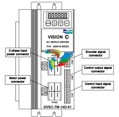
Designations of DOOSAN AC Servo Motor and Drive are as follows.
Please refer to this section for system installation and after service.
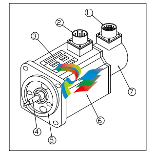
1)Encoder Connector 2)Power Connector 3)Name Plate 4)Shaft 5 )Flange 6 )Frame 7 )Encoder
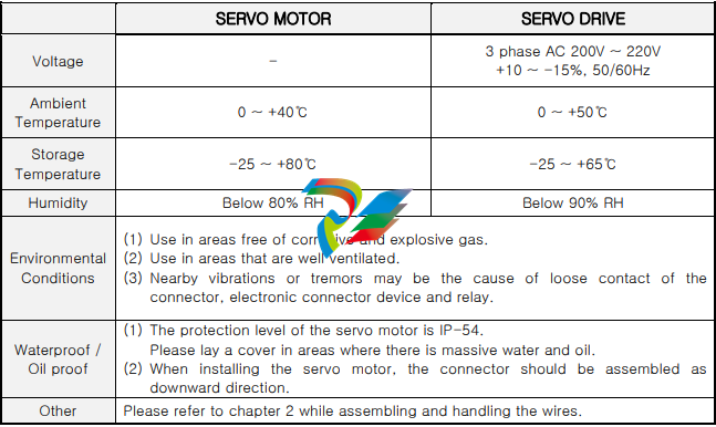
1.2. Environmental conditions
This product was designed for indoor usage.
Caution : If used in different circumstances and environment other than stated below, damages
may occur.
Please use under the following conditions.
1.3. Installation method
1.3.1. Assembling of the servo motor
▷ Warning: While assembling the servo motor, avoid dropping it.
▷ Caution: While mounting the servo motor horizontally, the connector should be assembled
facing downward.
▷ The servo motor can be mounted horizontally or vertically.
▷ To prevent vibrations and extend the life of coupling and bearing, the motor shaft and the loading
shaft should be precisely aligned. Use flexible coupling when connecting directly to the load.
① The outer part of the coupling should be measured at four equidistant points each 90˚ apart,
and the gap between the maximum and the minimum readings should not exceed 0.03㎜.
② The center point of the motor and the loading shaft should be precisely aligned.
▷ Avoid excessive radial and thrust load to the motor shaft and also avoid impact that is more
than 10G when mounting the gear, coupling, pulley and etc. at the same time.
▷ A minus load means continuous operation in the regenerative braking state, when the motor is
rotated by load. The regenerative braking capacity of the servo drive is short term rated
specification equivalent to stop time of the motor. Thus, it should not be used in minus load that
generates continuous regenerative braking.
ex) Servo system for descending objects(without counterweight)
▷ The admissible load inertia into the motor shaft is within 5 times than the inertia of applied servo
motor. If it exceeds this, during deceleration it may cause regenerative malfunction.
The following steps should be taken if the load inertia exceeds more than 5 times the inertia of
the servo motor.
- Reduce the current limit. – Decelerate slowly.(Slow Down)
- Lower the maximum speed in use.
1.3.2. Mounting of the servo drive
▷ Warning: To prevent electric shock, turn off the power while mounting or uninstalling.
▷ While installing the panel, the size of the panel, cooling and wiring should be considered in
order to maintain a difference of temperature below 5℃ between the panel temperature and the
surrounding temperature in accordance with heat value of the equipment and box size.
▷ If a heating element is placed nearby, the surrounding temperature of the servo drive should be
maintained below 55℃ at all cases despite temperature rise by convection and radiation. Use a
fan to ventilate sealed inner air, and proper ventilation should be used for convection of the air.
▷ If a vibrating element is placed nearby, the drive should be mounted on shock absorbing surface.
▷ If the servo drive be exposed to corrosive gas for a long time, may cause damages to connecting
devices such as relay and circuit breaker, thus it should be avoided.
▷ Environmental conditions such as high temperature, high humidity, excessive dust and metal
particles should be avoided.
◆ Mounting method
▷ There should be a space wider than 100㎜ below and above the servo drive.
▷ There should be a space wider than 30㎜ on both sides of the servo drive.
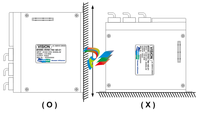
▷ Mount the servo drive vertically. Do not use if it is mounted horizontally.
1.4. Wiring
▶ For signal lines and encoder lines, use twisted lines or multi-core shielded twisted-pair lines.
The length for command input lines should be maximum 3m, and the encoder line should be
maximum 10m or less.
Wiring must be done in shortest distance and the remaining length should be cut.
▶ The ground circuit should be a thick line. Usage of third-class grounding or above (ground
resistance 100Ω or less) is recommended. Also, make sure to ground at one-point grounding.
▶ The following precautions should be taken to avoid malfunction due to noise.
- The noise filter should be placed as near as possible.
- Mount a surge absorber to the coil of the relay, electromagnetic contacts, solenoids and etc.
- The power line (AC input, motor input line) and the signal line should be placed 30㎝ apart
or more. Do not put them into the same duct or tie them in a bundle.
- If the power source of the servo drive is used in common with an electric welder or electrical
discharge machine, or a high-frequency noise source is present, attach noise filter to the
power or the input circuits.
- Since the core wire of the signal line cable is as thin as only 0.2 ~ 0.3㎟, excessive force to the
line should be avoided to prevent damages.
1.5. Noise treatment
For wiring and grounding of the servo drive, the effect of switching noise which is generated by the
built-in IPM should be reduced as much as possible. Unexpected effect by outside noise should be
reduced as much as possible.
▶ Grounding method
The servo drive supplies power to the motor according to the switching of the IPM device.
Thus the Cf dv/dt current flows from the power component to the floating capacity of the motor.




.png)


.png)


.png)


