
MOOGM-DRIVEINSTALLATION/START-UP GUIDE
M-DRIVE INSTALLATION/START-UP GUIDE
CAUTION
Hazardous Voltages. Can cause severe injury, death or damage to
equipment. The M-Drive should only be installed by a qualified
electrician.
Proper earth grounding of all electronic equipment is required for
successful operation. Connect a low impedance earth ground to
terminal 7 of connector J2.
Separate all logic and signal level wiring (J1, J3 and J4) from all
motor armature and AC power wiring (J2).
Shield all logic and signal wiring (J1, J3 and J4) and terminate to
earth ground at one point only
SCALING
After completing the required wiring of the M-Drive, follow the procedure below to scale the M-Drive for Master
format RPM operation. Complete this procedure before scaling the M-Drive for engineering units.
1. While pressing the ìCLEARî and ì7î keys on the keypad, apply AC power to the M-Drive
(loads factory default parameters).
2. Enter the pulses-per-revolution of the feedback sensor into CP-31. The keypad sequence for a 60 tooth gear
sensor is ìCode Selectî, ì3î, ì1î, ìEnterî, ì6î, ì0î, ìEnterî.
3. Enter the maximum system operating RPM into CP-20, CP-22, CP-34 and CP-37. If the feedback sensor is not
directly connected to the motor shaft, enter the maximum feedback sensor shaft RPM.
4. Press the ìSETSPEEDî key and enter ½ of the RPM entered in Step 3.
5. Press the RUN pushbutton.
6. Verify the motor direction is forward (exchange A1 and A2 if not forward).
7. Press the ìTACHî key. Verify an RPM reading appropriate to the motor setpoint speed.
8. Press the R-Stop pushbutton.
The M-Drive is now properly scaled in RPMs. If engineering unit setpoints and/or displays other than RPMs are
desired, refer to Chapter 5 of the ìM-Drive User Manualî .
TUNING
If the drive system acts unstable or sluggish in response to setpoint or load changes, it may be necessary to tune the
M-Drive. Follow the procedure below to improve system performance:
1. Set CP-66 (Integral) and CP-67 (Derivative) to zero.
2. Reduce CP-65 (Gain) until the system goes unstable (erratic). Stability can be tested by moving between two
wide spread setpoint values. When instability is reached, increase the CP-65 number slightly until the system
stabilizes (larger values reduce the system gain).
3. Using only Gain, the system setpoint value may never be reached due to system losses. Reduce CP-66 (Integral)
until the system becomes unstable, then increase the Integral number slightly until the system stabilizes and the
desired setpoint value is reached.
4. Derivative (CP-67) is only required if the system is too sluggish after setting the Gain and Integral terms. The
Derivative value, like Gain, should be reduced to the point of instability, then increased slightly until the system
regains stability
FOLLOWER OPERATION
Complete the ìScalingî and ìTuningî procedures for Master mode (Page 2) before proceeding with Follower opera
tion. To enable Follower operation, follow the procedure below:
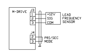
1. Wiring additions:
2. Enter the pulses-per-revolution of the lead (External Reference) sensor into CP-30 (PPR Ext Ref).
3. Enter the maximum system operating RPM of the lead motor (or sensor shaft if not directly connected to the
motor) into CP-36 (RPM Ref Secondary Max).
4. The M-Drive is now scaled for ratio follower operation. Setpoint and display values are in ratio of follower/lead.
If engineering unit setpoints and/or displays other than ratio are desired, refer to Chapter 5 of the ìM-Drive User
Manualî.
5. Enter the desired operating ratio into CP-3 (Follower Setpoint).
TROUBLE-SHOOTING
Master Mode: Motor Will Not Run
Step 1: Check MV-53 (Control State).
a) Should be ì32î (Run).
b) If not ì32î, check the Run, R-Stop and F-Stop wiring.
Step 2: Check MV-45 (Scaled Reference).
a) Should not be zero.
b) Press ìSETSPEEDî and enter a midrange value setpoint.
c) Enter a value greater than max motor speed (CP-34) into CP11 (Maximum Limit).
d) Enter a ì1î into CP-61 (Scaling Mode Pri) and CP-63 (Display Mode Pri).
Step 3: Check MV-46 (Ramped Reference).
a) Should not be zero.
b) If MV-46 is zero, check MV-54 for a value of 247 or 255.
c) If MV-54 is not 247 or 255, check wiring according to Chapter 3 of the ìM-Drive User Manualî.
Step 4: Check MV-47 (Output).
a) Should not be ì0î or ì100î.
b) If ì0î, then return to step 1 of ìScalingî.
c) If ì100î, check wiring to motor.
Step 5: If armature contactor is used, make sure it is energized.
Master Mode: Motor At Full Speed
Step 1: Press ìSETSPEEDî and enter midrange setpoint.
Step 2: Check MV-43 (Feedback Frequency).
a) Should not be zero.
b) Check that signal is present at feedback input (J3 Pins 5 and 6).
c) Check the feedback configuration jumpers per Chapter 2 of the ìM-Drive User Manualî.
Step 3: Stop the M-Drive.
Step 4: If motor does not stop, check MV-47 (Output).
a) Should be zero.
b) Check MV-53: Should be ì64î or ì128î.
c) If not, check R-Stop and F-Stop wiring.
Step 5: If motor is still running, suspect false-fired or bad SCRís.
Follower Mode: Motor Will Not Run
Step 1: Check unit out in Master Mode first.
Step 2: Check MV-54 (Control Mode)
a) Should be less than 128.
b) If not, check wiring to verify that Follower mode has been selected.
-
 GE IS200AEPBH1B IS200AEPBH1B‑REV‑AA Pitch-Charger Control PCB Board
 -
 GE IS200EDEXG1ADA EX2100 SCR Trigger Control Board
 -
 GE 151X1207CK01SA01 IS200EDEXG1A EX2100 SCR
 -
 GE 151X1233DD02SA02 IS200AEPBH1B - Variant for pitch control charger assembly
 -
 GE 151X1233DB01SA01 IS200AEPBH1B - 10kW Wind Power Converter
 -
 GE 151X1233DB01SA01R | IS200AEPBH1B 10KW Converter
 -
GE 151X1233DD01SA02 Pitch Battery Charger (109W6931P001)
-
GE 151X1233DD01SA02 Pitch Battery Charger Assy IS200AEPBH1B
-
 GE 151X1233DB02SA02 Rev A IS200AEPBH1B Wind Turbine Converter
 -
 GE 151X1207CK02SA02 SCR 4400 V 1850 A IS200EDEXG1ADA General Electric EX2100
 -
 Triconex 3723X 32-Channel TMR Analog Input Module with HART
 -
 SHINKAWA VM-21G SIGNAL CONDITIONER SOCKET
 -
SHINKAWA VM-21R REVOLUTION SIGNAL CONDITIONER
-
SHINKAWA VM-21T DISPLACEMENT INPUT THRUST SIGNAL CONDITIONER
-
SHINKAWA VM-21D 6-WIRE LVDT SIGNAL CONDITIONER
-
 SHINKAWA VM-21P 3-WIRE LVDT SIGNAL CONDITIONER
 -
SHINKAWA VM-21A VIBRATION SIGNAL CONDITIONER
-
SHINKAWA VM-21K DISPLACEMENT INPUT VIBRATION SIGNAL CONDITIONER
-
 SHINKAWA VM-25S01 CONDITION MONITORING SYSTEM
 -
SHINKAWA VM-25 CONDITION MONITORING SYSTEM
-
SHINKAWA VM-772B DEVICE CONFIG
-
SHINKAWA VM-771B MCL VIEW
-
 SHINKAWA VM-76B INSTRUMENT RACK
 -
SHINKAWA VM-75B POWER SUPPLY MODULE
-
 SHINKAWA VM-742B NETWORK COMMUNICATION MODULE
 -
 SHINKAWA VM-741B LOCAL COMMUNICATION & PHASE MARKER MODULE
 -
SHINKAWA VM-722B 9-CHANNEL RELAY MODULE
-
SHINKAWA VM-707B AERODERIVATIVE GAS TURBINE MONITOR MODULE
-
 SHINKAWA VM-706B ROD DROP MONITOR MODULE
 -
 SHINKAWA VM-705B 18-CHANNEL TEMPERATURE MONITOR MODULE
 -
 SHINKAWA VM-704B TEMPERATURE MONITOR MODULE
 -
 SHINKAWA VM-702B ABSOLUTE VIBRATION MONITOR MODULE
 -
SHINKAWA VM-701B VIBRATION / DISPLACEMENT MONITOR MODULE
-
 SHINKAWA MODEL VM-5X INTERFACE UNIT
 -
 SHINKAWA MODEL VM-5W2 DUAL POWER SUPPLY INSTRUMENT RACK
 -
 SHINKAWA MODEL VM-5H4 INSTRUMENT RACK (for VM-5Z5.6.7)
 -
SHINKAWA MODEL VM-5G SINGLE UNIT INSTRUMENT RACK
-
SHINKAWA MODEL VM-5Z5,6,7 POWER SUPPLY UNIT
-
SHINKAWA MODEL VM-5Y1,2,3 RELAY MODULE UNIT
-
 SHINKAWA MODEL VM-5P3 PHASE MARKER UNIT
 -
 SHINKAWA MODEL VM-53 DUAL COMMUNICATION UNIT
 -
 SHINKAWA MODEL VM-52 BOTTOM HOLD MONITOR
 -
SHINKAWA MODEL VM-51 ROD DROP MONITOR
-
SHINKAWA MODEL VM-5R TACHOMETER
-
SHINKAWA MODEL VM-5S DUAL TACHOMETER
-
SHINKAWA MODEL VM-5A DUAL VALVE
-
SHINKAWA MODEL VM-5E DUAL CASE
-
SHINKAWA MODEL VM-5L COMPLEMENTARY INPUT
-
SHINKAWA MODEL VM-5N RAMP DIFFERENTIAL
-
SHINKAWA MODEL VM-5D DUAL DIFFERENTIAL
-
SHINKAWA MODEL VM-5T DUAL THRUST MONITOR
-
SHINKAWA MODEL VM-5C ECCENTRICITY MONITOR
-
SHINKAWA MODEL VM-5M DUAL PATH MONITOR
-
SHINKAWA MODEL VM-5B DUAL ACCELERATION MONITOR
-
SHINKAWA MODEL VM-5U DUAL SEISMIC MONITOR
-
SHINKAWA MODEL VM-55 VIBRATION MONITOR
-
 SHINKAWA VM-742B1-5 VIBRATION MONITORING SYSTEM CARD
 -
 Shinkawa PSP-17B P-24-64A P-24-64B Circuit Board Module
 -
 SHINKAWA MGP-67 PCB
 -
 Shinkawa JBP-278 P-22-48A-1 P-22-48B-1 Circuit Board Module
 -
 Shinkawa VM-721B 18-CHANNEL RELAY MODULE
 -
Shinkawa FRP-337 P-26-54A P-26-54B Circuit Board Module
-
 Shinkawa CPP-111 P-25-59A P-25-59B Circuit Board Module
 -
Shinkawa WKN-142K2-2 Vibration Transmitter
-
 SHINKAWA VL-202A08L-1012 Rotor Position Monitor Probe Sensor
 -
 Shinkawa CPP-128 P-26-74A P-26-74B Circuit Board Module
 -
 Honeywell 51402755-100 PROCESSOR CARD
 -
 Honeywell 51107595-100 Power
 -
HONEYWELL 51304544-100 Control Board
-
 HONEYWELL 51109919-100 BOARD
 -
 HHoneywell 51204160-175 Digital Input Module
 -
 Honeywell 51304754-150 High Level Analog Input Module
 -
 HONEYWELL 51304690-100 DIGITAL INPUT CARD
 -
 Honeywell 51401635-150 COMM CONTROL
 -
 HONEYWELL 51204174-175 MC-TAOY 52 ANALOG OUTPUT BOARD
 -
 HONEYWELL 51400596-100
 -
 HONEYWELL 51401291-100 board card
 -
 HONEYWELL 51401642-150 I/O LINK MODULE
 -
 Honeywell LCN‑E Hub Power Supply 38500148‑300
 -
 Honeywell LCN‑E Hub redundant 38500143‑202 Twisted‑pair LCN
 -
 Honeywell LCN‑E Hub non‑redundant,38500143‑102
 -
Honeywell Enhanced Micro‑TDC‑3000 System Unit MX‑DTAC01K2
-
 Honeywell Enhanced Micro‑TDC‑3000 System Unit MX‑DTAB01K2
 -
 Honeywell Enhanced Micro‑TDC‑3000 System Unit MT11‑520
 -
 Honeywell STI‑CE Smart Transmitter Interface 51304516‑150
 -
 Honeywell STI Smart Transmitter Interface 51304516‑100 MC‑PSTX02
 -
 Honeywell ulse Counter IOP,51304386‑100.MU‑PPIX02
 -
 Honeywell DO Digital Output IOP‑CE 51304487‑150 CE version
 -
.png) Honeywell DO Digital Output IOP 51304487‑100 MC‑PDOX02
Honeywell DO Digital Output IOP 51304487‑100 MC‑PDOX02 -
 Honeywell TDC‑3000 SOE DI IOP,51402625-175 MC‑PDIS12
 -
 Honeywell TDC‑3000 DI Digital Input IOP‑CE 51304485‑150
 -
Honeywell TDC‑3000 DI Digital Input IOP 51304485‑100 MC‑PDIX02
-
Honeywell TDC‑3000 AO Analog Output IOP 51304757‑100 MU‑PAOX02
-
Honeywell TDC‑3000 TC Thermocouple IOP 51304756‑100 MU‑TAMT03
-
 Honeywell TDC‑3000 51304755‑100 MU‑TAMR03
 -
 Honeywell TDC‑3000 LLAI Multiplex AI IOP,51304362‑150
 -
 Honeywell TDC‑3000 HLAI Analog Input IOP‑CE,51304363‑150
 -
 Honeywell TDC‑3000 HLAI Analog Input IOP,51304363‑100.4‑20mA
 -
Honeywell TDC‑3000 HPM Power Supply,51401731‑100
-
 Honeywell TDC‑3000 Standard 1986.HPM High‑Performance PM CPU,51402362‑100
 -
Honeywell TDC‑3000 APM Advanced Process Manager CPU,51304459‑100
-
Honeywell TDC‑3000 Standard 1986.PM Process Manager CPU,51304362‑100
-
Honeywell TDC‑3000 NIM Network Interface Module,51304481‑200
-
 Honeywell TDC‑3000 NIM Network Interface Module 51304481‑100
 -
 Honeywell TDC‑3000 BASIC,LCN Terminator Resistor,30732052‑001.Coaxial
 -
Honeywell TDC‑3000 BASIC,Hiway Coupler,30753732-001
-
 Honeywell TDC‑3000 BASIC,LEPIU Low‑Energy PIU,4DP7APCFA309
 -
Honeywell TDC‑3000 BASIC,HLPIU High‑Level PIU,4DP7APCFA106
-
Honeywell TDC‑3000 BASIC,Multifunction Controller(TDC‑2000 DHW),4DP7MFA103
-
 Honeywell TDC‑3000 BASIC,Extended Controller(TDC‑2000 DHW),4DP7AXA102
 -
Honeywell TDC‑3000 BASIC,Basic Controller(TDC‑2000 DHW),4DP7BBA101
-
Honeywell TDC‑3000 BASIC,XLCNE2 LCN Extender,51305508‑100.Coaxial LCN
-
 Honeywell TDC‑3000 BASIC,E‑PLCG PLC Gateway,51400997‑200
 -
 Honeywell TDC‑3000 BASIC,PLNM Plant Network Module,51401163‑100
 -
 Honeywell TDC‑3000 BASIC,CG Computer Gateway,80360206‑001
 -
 Honeywell TDC‑3000 BASIC,HG High‑Speed Gateway,51304526‑100
 -
 Honeywell TDC‑3000 BASIC,HM History Module,51191596‑200
 -
Honeywell TDC‑3000 BASIC,HM History Module,51191596‑100
-
Honeywell TDC‑3000 BASIC,AM Application Module CPU,51401551‑800.K2LCN‑8
-
Honeywell TDC‑3000 BASIC,AM Application Module CPU,51401551‑600.K2LCN‑6
-
 Honeywell TDC‑3000 BASIC,AM Application Module CPU,51401551‑400,K2LCN‑4
 -
 Honeywell TDC‑3000 BASIC,AM Application Module CPU,51401551‑300.K2LCN‑3
 -
Honeywell TDC‑3000 BASIC,AM Application Module CPU,51401551‑200,K2LCN‑2
-
 Honeywell TDC‑3000 BASIC,US Universal Station CPU,51401288‑200
 -
TDC‑3000 BASIC,US Universal Station CPU,51401288‑100
-
 SHINKAWA VM-21P1 Signal Conditioner 0-50MM 24VDC
 -
 Shinkawa RiverNew Vibration Transducer VK202 Series
 -
 Shinkawa Electric VM-3E2 Vibration Monitor Module


