
MOOGM-DRIVEINSTALLATION/START-UP GUIDE
M-DRIVE INSTALLATION/START-UP GUIDE
CAUTION
Hazardous Voltages. Can cause severe injury, death or damage to
equipment. The M-Drive should only be installed by a qualified
electrician.
Proper earth grounding of all electronic equipment is required for
successful operation. Connect a low impedance earth ground to
terminal 7 of connector J2.
Separate all logic and signal level wiring (J1, J3 and J4) from all
motor armature and AC power wiring (J2).
Shield all logic and signal wiring (J1, J3 and J4) and terminate to
earth ground at one point only
SCALING
After completing the required wiring of the M-Drive, follow the procedure below to scale the M-Drive for Master
format RPM operation. Complete this procedure before scaling the M-Drive for engineering units.
1. While pressing the ìCLEARî and ì7î keys on the keypad, apply AC power to the M-Drive
(loads factory default parameters).
2. Enter the pulses-per-revolution of the feedback sensor into CP-31. The keypad sequence for a 60 tooth gear
sensor is ìCode Selectî, ì3î, ì1î, ìEnterî, ì6î, ì0î, ìEnterî.
3. Enter the maximum system operating RPM into CP-20, CP-22, CP-34 and CP-37. If the feedback sensor is not
directly connected to the motor shaft, enter the maximum feedback sensor shaft RPM.
4. Press the ìSETSPEEDî key and enter ½ of the RPM entered in Step 3.
5. Press the RUN pushbutton.
6. Verify the motor direction is forward (exchange A1 and A2 if not forward).
7. Press the ìTACHî key. Verify an RPM reading appropriate to the motor setpoint speed.
8. Press the R-Stop pushbutton.
The M-Drive is now properly scaled in RPMs. If engineering unit setpoints and/or displays other than RPMs are
desired, refer to Chapter 5 of the ìM-Drive User Manualî .
TUNING
If the drive system acts unstable or sluggish in response to setpoint or load changes, it may be necessary to tune the
M-Drive. Follow the procedure below to improve system performance:
1. Set CP-66 (Integral) and CP-67 (Derivative) to zero.
2. Reduce CP-65 (Gain) until the system goes unstable (erratic). Stability can be tested by moving between two
wide spread setpoint values. When instability is reached, increase the CP-65 number slightly until the system
stabilizes (larger values reduce the system gain).
3. Using only Gain, the system setpoint value may never be reached due to system losses. Reduce CP-66 (Integral)
until the system becomes unstable, then increase the Integral number slightly until the system stabilizes and the
desired setpoint value is reached.
4. Derivative (CP-67) is only required if the system is too sluggish after setting the Gain and Integral terms. The
Derivative value, like Gain, should be reduced to the point of instability, then increased slightly until the system
regains stability
FOLLOWER OPERATION
Complete the ìScalingî and ìTuningî procedures for Master mode (Page 2) before proceeding with Follower opera
tion. To enable Follower operation, follow the procedure below:
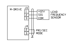
1. Wiring additions:
2. Enter the pulses-per-revolution of the lead (External Reference) sensor into CP-30 (PPR Ext Ref).
3. Enter the maximum system operating RPM of the lead motor (or sensor shaft if not directly connected to the
motor) into CP-36 (RPM Ref Secondary Max).
4. The M-Drive is now scaled for ratio follower operation. Setpoint and display values are in ratio of follower/lead.
If engineering unit setpoints and/or displays other than ratio are desired, refer to Chapter 5 of the ìM-Drive User
Manualî.
5. Enter the desired operating ratio into CP-3 (Follower Setpoint).
TROUBLE-SHOOTING
Master Mode: Motor Will Not Run
Step 1: Check MV-53 (Control State).
a) Should be ì32î (Run).
b) If not ì32î, check the Run, R-Stop and F-Stop wiring.
Step 2: Check MV-45 (Scaled Reference).
a) Should not be zero.
b) Press ìSETSPEEDî and enter a midrange value setpoint.
c) Enter a value greater than max motor speed (CP-34) into CP11 (Maximum Limit).
d) Enter a ì1î into CP-61 (Scaling Mode Pri) and CP-63 (Display Mode Pri).
Step 3: Check MV-46 (Ramped Reference).
a) Should not be zero.
b) If MV-46 is zero, check MV-54 for a value of 247 or 255.
c) If MV-54 is not 247 or 255, check wiring according to Chapter 3 of the ìM-Drive User Manualî.
Step 4: Check MV-47 (Output).
a) Should not be ì0î or ì100î.
b) If ì0î, then return to step 1 of ìScalingî.
c) If ì100î, check wiring to motor.
Step 5: If armature contactor is used, make sure it is energized.
Master Mode: Motor At Full Speed
Step 1: Press ìSETSPEEDî and enter midrange setpoint.
Step 2: Check MV-43 (Feedback Frequency).
a) Should not be zero.
b) Check that signal is present at feedback input (J3 Pins 5 and 6).
c) Check the feedback configuration jumpers per Chapter 2 of the ìM-Drive User Manualî.
Step 3: Stop the M-Drive.
Step 4: If motor does not stop, check MV-47 (Output).
a) Should be zero.
b) Check MV-53: Should be ì64î or ì128î.
c) If not, check R-Stop and F-Stop wiring.
Step 5: If motor is still running, suspect false-fired or bad SCRís.
Follower Mode: Motor Will Not Run
Step 1: Check unit out in Master Mode first.
Step 2: Check MV-54 (Control Mode)
a) Should be less than 128.
b) If not, check wiring to verify that Follower mode has been selected.
Step 3: Check MV-53 (Control State)
a) Should be ì32î (Run).
b) If not, check Run, R-Stop and F-Stop wiring.
Step 4: Check MV-41 (External Reference Frequency).
a) Should display the lead sensor frequency.
b) If not, check signal at External Reference Frequency input, and the configuration jumpers per Chapter 2
of the ìM-Drive User Manualî.
Step 5: Check MV-45 (Scaled Reference).
a) Should not be zero.
b) If zero, press ìSETSPEEDî and enter a non-zero ratio setpoint.
c) Check CP-11 (Maximum Limit) and enter a value greater than CP-37 (RPM Fdbk Secondary Max).
-
 HIRSCHMANN MSM20-M2M2M2M2SY9HH9E Ethernet media modul
 -
 HIRSCHMANN SPIDER-PL-20-05T1999999TWVHHHH Industrial Ethernet Rail Switch
 -
 Hirschmann SPIDER-PL-20-07T1M2M299TWVHHHH Industrial ETHERNET Rail Switch
 -
.png) Hirschmann (Belden) RS20-1600M2M2SDAEHC09.1.00 DIN-rail managed industrial Fast Ethernet switch
Hirschmann (Belden) RS20-1600M2M2SDAEHC09.1.00 DIN-rail managed industrial Fast Ethernet switch -
 Hirschmann (Belden) RS30-1602O6O6TDAPHC09.1.00 DIN-rail managed industrial Ethernet switch
 -
 Hirschmann (Belden) RS30-2402O6T1SDAPHH09.0.13 DIN-rail industrial Ethernet switch
 -
Hirschmann (Belden) SPIDER-PL-20-04T1S29999TY9HHHH Ethernet DIN-rail switch
-
 HIRSCHMANN RS20-1600T1T1SDAUHX Switch
 -
 HIRSCHMANN BRS42-0012OOOO-SPCZ99HHSES industrial switch
 -
 Hirschmann RS20-0800S2S2TDHPHH09.0.14 Fast Ethernet DIN rail switch.
 -
 HIRSCHMANN MM20-Z6Z6M2M2SAHH Hybrid Fast Ethernet Media Module
 -
 HIRSCHMANN MM20-Z6Z6T1T1SAHH hot-swappable hybrid Fast Ethernet Media Module
 -
 HIRSCHMANN MM20-P9P9T1T1SAHH Hybrid Fast Ethernet Media Module
 -
 HIRSCHMANN MM20-M4T1T1T1SAHH Hybrid Fast Ethernet Media Module
 -
 HIRSCHMANN MM20-M4M4T1T1SAHH Hybrid Fast Ethernet Media Module
 -
 HIRSCHMANN MM20-M2M2M2M2SZHH Ethernet media module
 -
HIRSCHMANN MM20-M2M2M2M2SAHH Ethernet media module
-
 HIRSCHMANN MM20-T1T1T1T1EBH 4-port Fast Ethernet Copper Cable Media Module
 -
HIRSCHMANN MM20-T1T1T1T1SAHH 4-port Fast Ethernet Copper Cable Media Module
-
HIRSCHMANN MM20-T1T1T1T1SAHH 4-port Fast Ethernet Copper Cable Media Module
-
 HIRSCHMANN MM20-Z6Z6EBH Hot-swappable fast Ethernet media module
 -
 HIRSCHMANN MM20-Z6Z6SAHH Ethernet media module
 -
HIRSCHMANN MM20-Z6Z6Z6Z6EBH Industrial Media Module
-
 MSM40-T1T1T1TZ9HH9E99.9.99 HIRSCHMANN Switch
 -
 HIRSCHMANN MS20-0800SAAEHC / MS20-0800SAAEHC0 8-port modular Layer 2 management Ethernet switch
 -
 Hirschmann RSPM20-4T14T1SZ9HHS9 Switch RSPM20-4T14T1SZ9HHS9
 -
 HIRSCHMANN RS20-1600M2M2SDAEHH09.1. RS20/30/40 Managed Switch configurator
 -
HIRSCHMANN RS20-1600M2M2SDAEHX09.0.00 Ethernet switch
-
 HIRSCHMANN BELDEN SPIDER-PL-20-07T1M2M299TY9HHHH / SPIDERPL2007T1M2M299TY9HHHH
 -
HIRSCHMANN MM3-1FXS2/3TX1 Switching Board Module
-
 HIRSCHMANN RSPE30-24044O7T99-ECCP999HHSE2A08.1.00 Industrial-grade fanless management-type Ethernet switch
 -
 HIRSCHMANN RS30-1602OOZZSDAEHC09.1.00 DIN-rail-mounted managed Layer 2 Ethernet switch
 -
 HIRSCHMANN MACH104-20TX-F Managed 24-port Full Gigabit 19" Switch
 -
 HIRSCHMANN Switch RS20-0800M4M4SDAE
 -
Hirschmann RS30-1602O6O6SDAEHH09.1. Management-type Ethernet switch
-
 Hirschmann RS30-1602OOZZSDAEHC09.0.10 Open rack-style Ethernet switch
 -
 HIRSCHMANN RSPE30-24044O7T99-SCCV999HHSI2SXX.X.XX High-Availability Seamless Redundancy
 -
HIRSCHMANN RSPE30-24044O7T99-SCCZ999HHSE2A DIN-rail Ethernet switch
-
HIRSCHMANN MM2-4TX1-EEC switch
-
HIRSCHMANN MSM40-T1T1T1T1TZ9HH9E99.9.99 Module
-
 HIRSCHMANN RS20 Rail Switch RS20-0400S4T1SDAEHC07.1.01
 -
 HIRSCHMANN M4-FAST8-SFP Fast Ethernet media module
 -
 HIRSCHMANN RS20-0400M2T1SDAP Managed Fast-Ethernet-Switch
 -
 HIRSCHMANN BELDEN SPIDER II 8TX/1FX EEC Industrial Ethernet Rail Switch
 -
HIRSCHMANN MM3-2FXS2/2TX1
-
 HIRSCHMANN RS2-4TX/1FX EEC Industrial Ethernet Rail Switch
 -
 RS30-0802O6O6SDAEHC09.0.10 HIRSCHMANN Switch
 -
 HIRSCHMANN m4-8TP-RJ45 Ethernet Media Module
 -
 HIRSCHMANN MSP30-24040SCZ9URHHE3A switch
 -
 Hirschmann rack MS30-1602SAAPHC
 -
 HIRSCHMANN RS2-FX/FX Industrial Switch Module
 -
Rs1txfx - Hirschmann - Rs1-Tx/Fx Rail Switch
-
RS20-0800S2S2SDAEHC09.1.00 HIRSCHMANN Commutator
-
 Hirschmann EAGLE20 TX/TX Industrial Security Router
 -
 Hirschmann SPIDER-SL-20-04T1S29999SY9HHHH Industrial Switch
 -
 HIRSCHMANN MAR1040-4C4C4C4C9999SMMHRHHXX.X. Gigabit Ethernet Switch configurator
 -
 Hirschmann MAR1040 Industrial Switch
 -
 HIRSCHMANN BELDEN RS30-1602O6O6SDAE
 -
Hirschmann RS20-1600M2M2SDAUHC Ethernet DIN rail switch
-
 HIRSCHMANN OCTOPUS 24M industrial switch
 -
 HIRSCHMANN RS20-1600T1T1SDAE Management-type Ethernet switch
 -
 HIRSCHMANN RS20-1600T1T1SDAUHH industrial switch
 -
HIRSCHMANN RS20-0800M2M2SDAPHC09.0.04 switch
-
 Hirschmann MR 8-03 24V DC Industrial Modular Bridge/Router
 -
 HIRSCHMANN RS20-0400M2T1SDAPHC08.0.01 Managed Switch
 -
 MACH1130 Hirschmann Industrial Switch
 -
 HIRSCHMANN 943824-002 SPIDER 5TX Industrial Ethernet Switch
 -
 HIRSCHMANN RS30-0802O6O6SDAEHC09.1.00 Managed Industrial Switch
 -
 HIRSCHMANN RS20-0400M2M2TDAEHC04.0.01 Industrial Switch
 -
 HIRSCHMANN BRS20-0600Z6Z6-STCZ99HHSES Industrial Switch
 -
 HIRSCHMANN MACH104-20TX-FR-L3P Industrial Ethernet Switch
 -
 HIRSCHMANN RS40-0009CCCCEDBPHH06.0.01 Industrial Switch
 -
 HIRSCHMANN RS2-3TX/2FX EEC Industrial Ethernet Switch
 -
 Hirschmann MACH 1020/1030 Fast/Gigabit Rack Mount Switches
 -
HIRSCHMANN RS20-0800M2M2SDAPHC09.0.14 Industrial Switch
-
 HIRSCHMANN RS20-1600T1T1SDAEHC09.0.04 Industrial Switch
 -
 HIRSCHMANN RSB20-0800T1T1EAABHH Industrial Switch
 -
 HIRSCHMANN MACH4002-48+4G-L3E Industrial Backbone Switch
 -
 HIRSCHMANN RS20-0400S2T1SDAE Industrial Managed Switch
 -
HIRSCHMANN RS20-0800S2T1SDAUHC Industrial Switch
-
 HIRSCHMANN RS20-2400S4S4SDAEHC09.0.14 industrial switch
 -
 HIRSCHMANN OS20-001200T5T5T5- TBBZ999HHNE3S 08.1.00 industrial switch
 -
HIRSCHMANN OS20-001200T5T5T5- TBBZ999HHNE3S 08.1.00 industrial switch
-
 HIRSCHMANN RS40-0009CCCCSDAEHH09.0.14 switch
 -
 Hirschmann RS20-1600T1T1SDAUHC Management-type Ethernet Switch
 -
 Hirschmann M1-8SFP Switche
 -
Hirschmann Industrial Ethernet Ruggedized Switch MACH1000 Family
-
 Basler Electric, Solid State Protective Relay, BE1-60
 -
BASLER ELECTRIC SR4A-2B15B3A Static Voltage Regulator
-
.png) BASLER ELECTRIC EXCITER DIODE MONITOR EDM-200
BASLER ELECTRIC EXCITER DIODE MONITOR EDM-200 -
.png) BASLER ELECTRIC DECS125-15-B2C5 DIGITAL EXCITATION CONTROL SYSTEM V 2.0.9
BASLER ELECTRIC DECS125-15-B2C5 DIGITAL EXCITATION CONTROL SYSTEM V 2.0.9 -
 BASLER ELECTRIC BE1-851 OVERCURRENT PROTECTION RELAY MECHANISM
 -
 Basler Electric BE1-51A / BE151A
 -
 Basler Electric BE1-40Q Loss of Excitation Relay
 -
 Basler Electric BE1-87G Variable Percentage Differential Relay
 -
 Basler Electric BE1-11 Protection System I5A3M2P2N0EA00
 -
 BASLER ELECTRIC DECS-200-1C Digital Excitation Control System
 -
 Basler Electric / Kohler BE1-11g Generator Protection Relay G5A3M2J2N0E000
 -
BASLER ELECTRIC DECS125-15 DIGITAL EXCITATION CONTROL SYSTEM
-
 BASLER ELECTRIC BE1-951 OverCurrent Protecton System
 -
Basler Electric DECS-200-1L Digital Excitation Control System
-
 Basler Electric DGC-2020HD-5NS1DNSBA Digital Genset Controller -
 -
 BASLER ELECTRIC BE1-81T1EE1WA0N1F / BE181T1EE1WA0N1F
 -
 BASLER ELECTRIC BE1-25M1EA6PN5R1F / BE125M1EA6PN5R1F
 -
 BASLER ELECTRIC DECS-250-LN1SN1N DIGITAL EXCITATION CONTROL SYSTEM
 -
Basler Electric DECS-250-CN2CN 1N Digital Excitation Control System Unit
-
 BASLER ELECTRIC DECS-300-C0N0 DIGITAL EXCITATION CONTROL SYSTEM
 -
 BASLER ELECTRIC BE1-87T-A1E-A1J-D0S1F / BE187TA1EA1JD0S1F
 -
BASLER ELECTRIC BE1-11-G6D1M0J2P0E000 Protection System
-
 BASLER ELECTRIC BE1-GPS100-E4N1H1N GENERATOR PROTECTION SYSTEM
 -
 Jaquet Relay card (Auxiliary module) FTV 3090 377Z-03985
 -
 Jaquet Trip Chain Control card FTBU 3034 377Z-05030
 -
 Jaquet with input card -E04 FTFU 3024 -E04 377Z-05855
 -
 Jaquet with input card -E03 FTFU 3024- E03 377Z-03983
 -
 Jaquet FTFU 3024- E02 377Z-03982 with input card -E02
 -
 Jaquet FTFU 3024-E01 377Z-03981 with input card -E01
 -
 Hirschmann RS20-2400T1T1SDAE Industrial Managed Ethernet Switch
 -
 Hirschmann BELDEN EAGLE30-04022O6TT999SCCV9HSE3F
 -
 Hirschmann MM3-2FXS2/2TX MICE Media Module
 -
 Hirschmann RS20-1600M2M2SDAPHC08.0.05 Industrial Managed Switch
 -
 Hirschmann OZD Profi 12M G12-1300 PRO Fieldbus Repeater
 -
Hirschmann SPIDER 4TX/1FX-ST EEC Industrial Ethernet Switch
-
 Hirschmann MM2-2FXM3/2TX1 MICE Media Module
 -
 Hirschmann RS20-2400M2M2SDAPHC09.0.14 Industrial Switch
 -
 Hirschmann RS20-0400M2M2SDAEHC07.1.05 OpenRail Switch
 -
 Hirschmann OZD Profi 12M G12-EEC Fieldbus Repeater
 -
HIRSCHMANN MDA422-1/2-3.5c-23/46 sensor
-
Hirschmann RS30-2402T1T1SDAUHC Managed Industrial Switch


