
ABBAutomatic Transfer Switch
I ON Transfer to LN1 Only available in automatic mode and remote test mode
O OFF Transfer to 0 position
II ON Transfer to LN2
Auto Select autiomatic mode, fault clearance and reset
Table 5. Buttons
4.3 Rotary switch settings
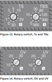
Transfer delay Ts The delay of transferring from the LN1 to the LN2 in automatic mode.
The options are 0, 1, 2, 3, 5, 10, 15, 20, 25, and 30 seconds.
Return delay TBs The delay of transferring from the LN2 to the LN1 in automatic mode.
The options are 0, 5, 10, 20, 30, 60, 120, 300, 600, and 900 seconds.
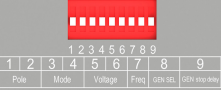
Overvoltage threshold OV (%) and undervoltage threshold UV (%) The benchmarks of the OV
and UV are the rated voltage of the switch. When the voltage is higher than the pre-set OV value
or lower than the preset UV value, the switch performs automatic transfer.
The value of OV can be 5%, 10%, 15%, 20%, 25%, and 30%. The
value of UV can be 5%, 10%, 15%, 20%, 25%, and 30%.
4.4 Dip switch setting
The 9-bit dip switch is used to set the working modes of transfer switch.
4.5 Terminal outputs and inputs
The switch has 11 bits of signal terminals for users to input and output signals

Figure 16. Terminals
Terminal
No. Function
1, 2 Remote test: connection for at least 100 ms for the switch to enter the remote test mode
3, 4 EMRG OFF: Input the 24VDC EMRG OFF signals for at least 1s until the switch transfers to the EMRG OFF
position and the EMRG OFF LED is on. At this time, the switch cannot enter the automatic or test mode and only handle operation is allowed. After the signal is canceled, press "AUTO" to quit EMRG OFF
5, 6 Generator start: generator start signal output. When the backup power is a generator, it is used to start (close signal) and stop (open signal) the generator. After the switch transfers to the normal power, the generator stop signal is sent after the preset delay for generator stop (see the ninth bit in section 4.4 for the generator stop delay setting).
7,8,9 Switch status feedback signal output.
10, 11 Alarm: The switch outputs consecutive alarm signals in EMRG OFF mode or refuses to perform operations. The alarm signals are cleared after quitting the EMRG OFF mode, fault recovered, or handle inserted.
Output Output contact relays are dry contactz and therefore external voltage supply is required.
contacts 24VDC or up to 250VAC max. 3A AC1
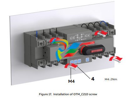
6. Installation
6.1 Installation method
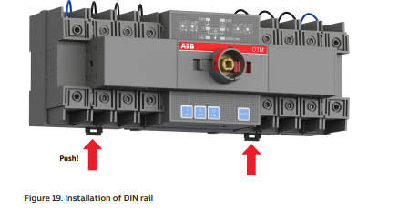
The switch can be installed using screws or a DIN rail. The fixed installation mode on the base board is as follows:
The DIN rail installation mode is as follows: First pry out the latch with an appropriate tool, as shown in Fig. 13
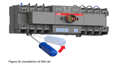
After attaching the switch to the DIN-rail, push the latch back to lock it
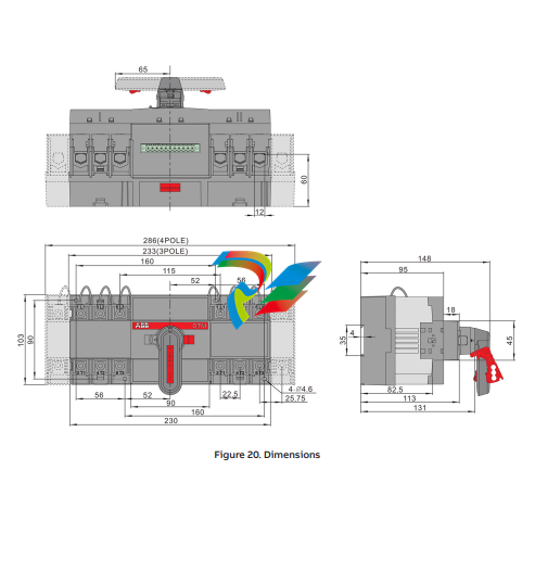
6.2 Installation dimensions
7. Optional accessories
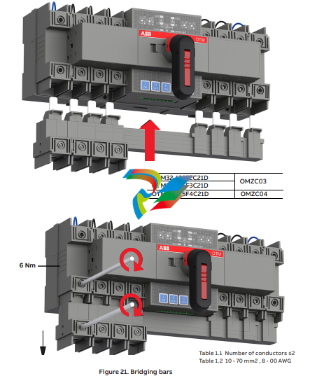
7.1 Bridging bars
7.2 Terminal shrouds
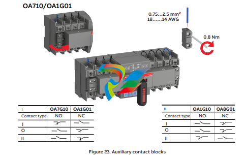
7.3 Auxiliary contact blocks
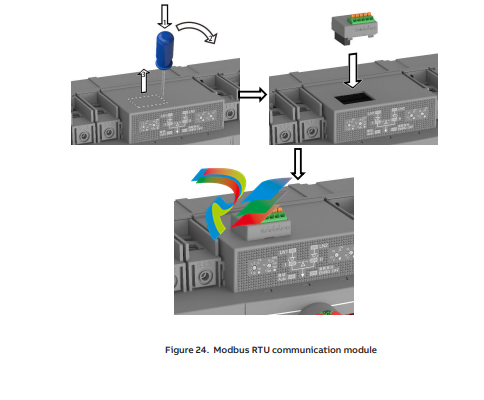
7.4 Modbus communication module
8. Maintenance and common troubleshooting
8.1 Maintenance
To ensure the operation reliability of switches, regular switching tests should be performed (once every 3 months) to confirm normal function.
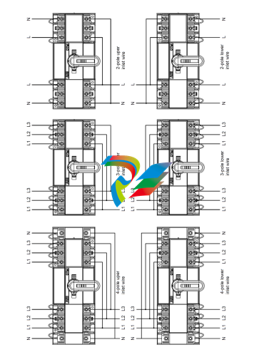
9. Appendix9.1 Wiring diagram
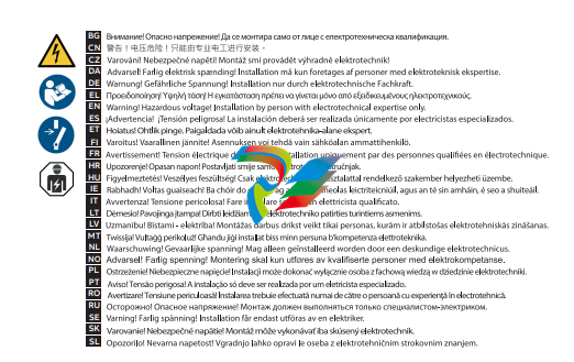
• Read through this instruction book carefully before working on the switch, and keep this instruction book safe for later reference
• The images provided in this instruction book are for illustration only and may not match the actual product exactly
• This instruction book is subject to change for product updates without prior notice
-
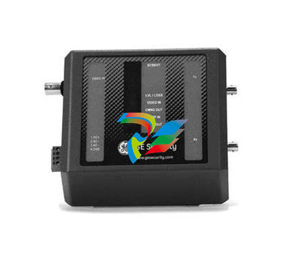 S739DVT Digital Valve Trip Module
 -
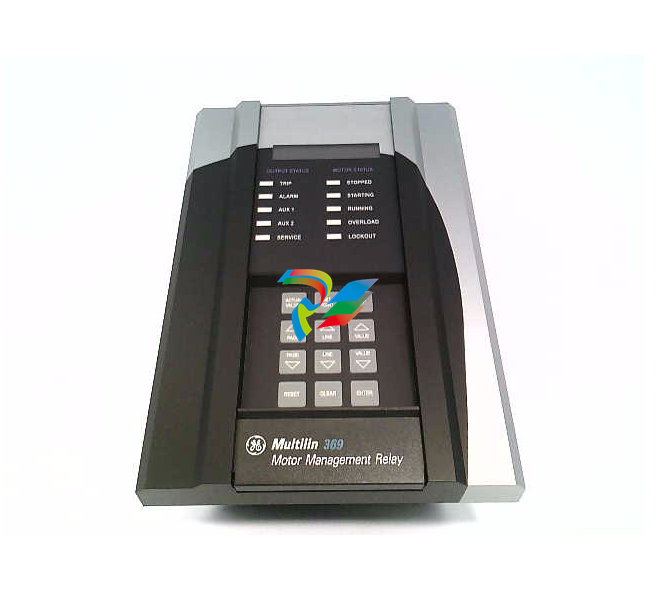 369-HI-R-M-F-E-H-E Motor Management Relay
 -
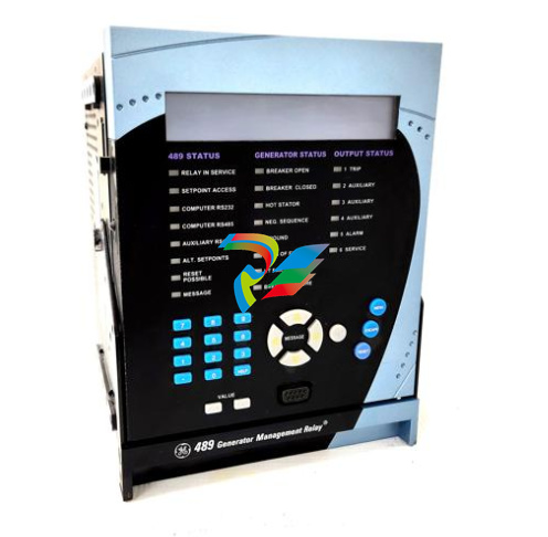 489-P5-HI-A20-E Multilin Relays
 -
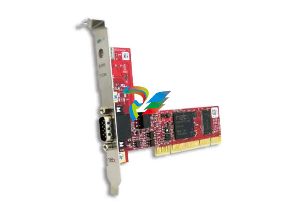 PC Card CIFX 50-CO – PCI
 -
 PC000087524/01 Power module
 -
 SR469-P5-H-A20-T Multi-Function Motor Protection Relay
 -
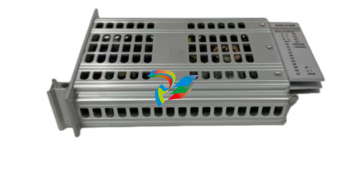 WES5120 2340-21005 On site controller main station unit
 -
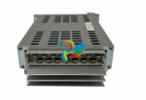 WES5120 2340-21003 Analog output module
 -
 Alstom IRVI20 - REGULATION INTERFACE BOARD
 -
 ABB DRIVEMONITOR VERSION 4000 DRIVE MODULE RBOX316-ABB-00
 -
D20MIC10BASE-T 820-0756 Network card
-
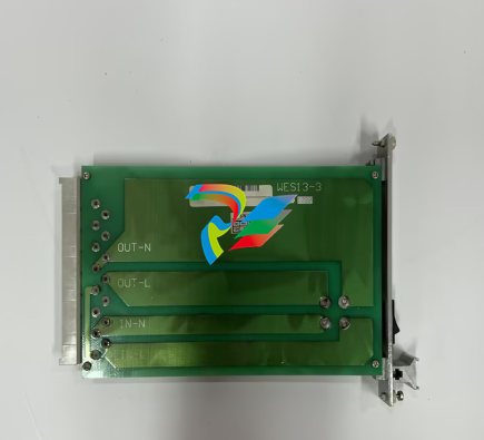
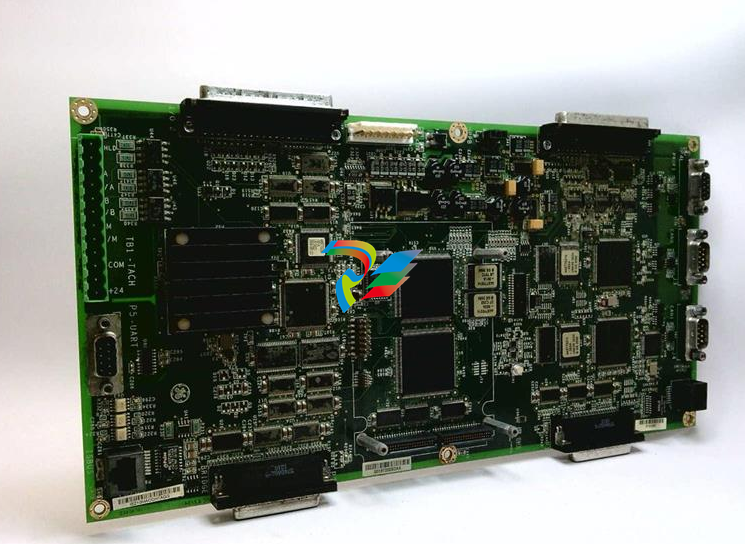 WES13-3 5167-0001-0210 CPU/Auxiliary Control board
 -
 WES13-3 2508-21001 Embedded digital module
 -
D20ME 526-2005-216943 control module
-
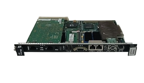
 D20EME 0526-21170-1 Enhanced Master Communications Module for D20 Substation RTUs
 -
.jpg) 2400-21004 / 2010-3101-0442 – Redundant Power Supply Module for Mark VIe Turbine Control
2400-21004 / 2010-3101-0442 – Redundant Power Supply Module for Mark VIe Turbine Control -
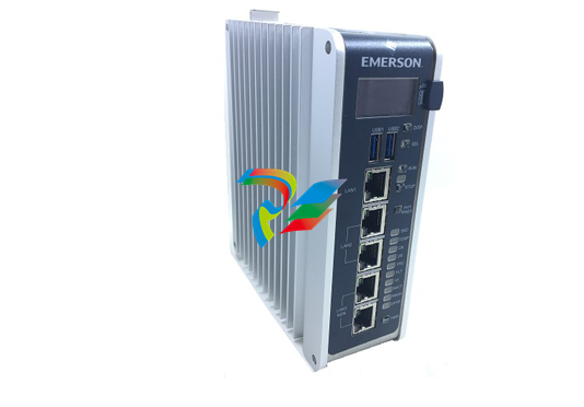 PACSystems™ IC695CPE400 RX3i 64 MB
 -
 DS200DCFBG2BNC DC2000 DC Feedback Board
 -
 OLDI Ethernet interface module 56SAM-844
 -
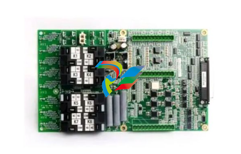
 IS200BPPBH2CAA Mark VIe Power Supply Module
 -
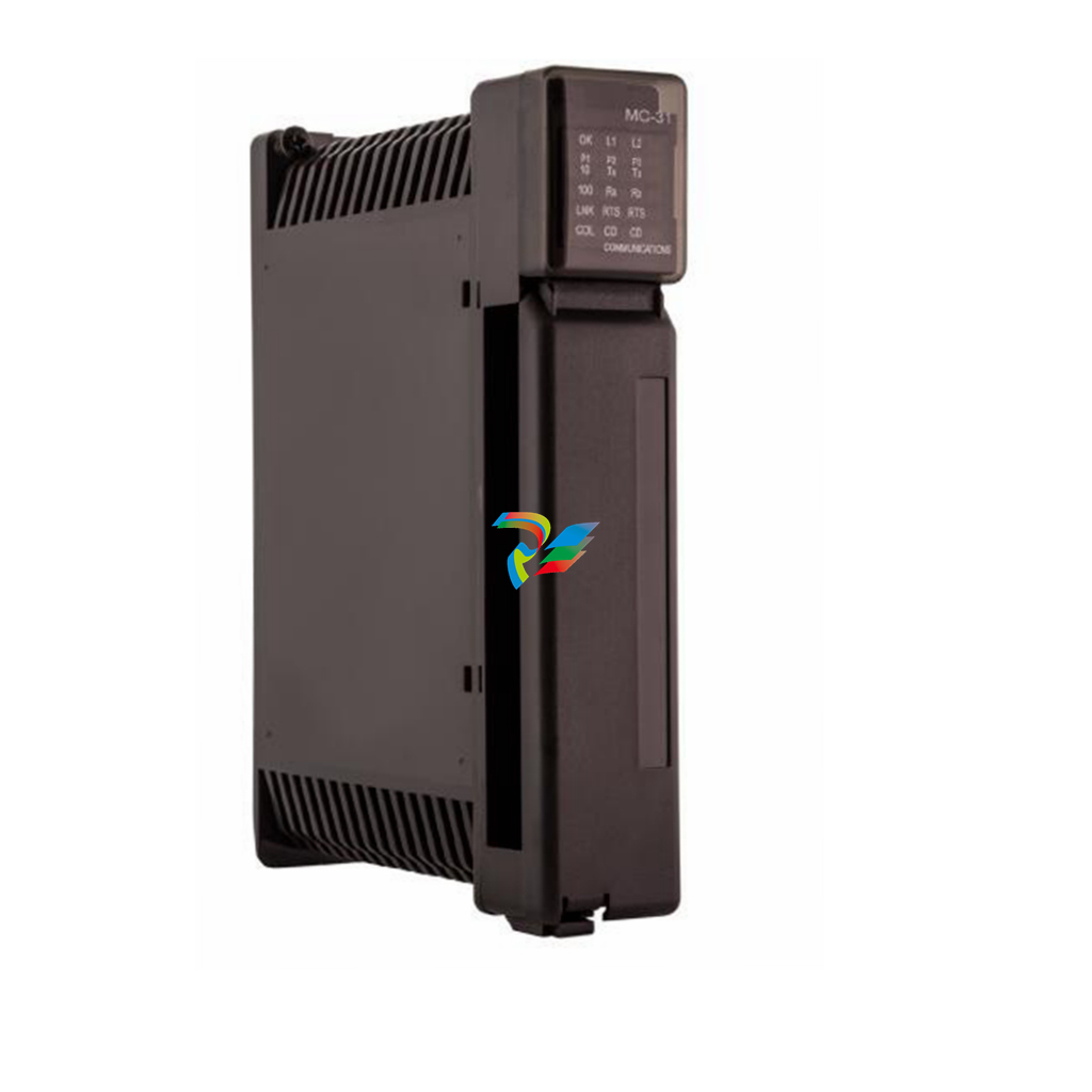
 IS210MACCH2AEG Motor Control and Communication Module
 -
 IS210MACCH2AGG Mark VIe Speedtronic Turbine Control Module
 -
 IS200AEPAH1AFD Printed circuit board
 -
IS200AEPAH1ACB Analog I/O Module
-
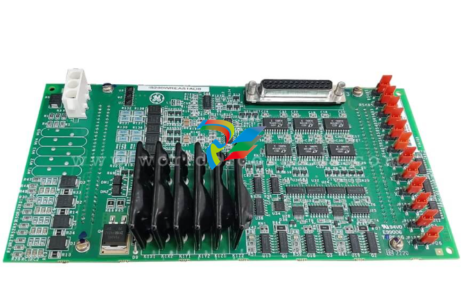 IS200WREAS1ADB AERO TRIP TB DBRD sub-board
 -
 IS200WETAH1AEC large board component made Mark VI system
 -
 IS200AEPAH1AHD A High-Precision Excitation Control Board for Turbine Systems
 -
 IS200WEMAH1AEA Control board
 -
IS210MACCH1AGG processor card
-
 IS230TNRLH1B Discrete Output Modular Assembly
 -
 Mark V Series DS200PCCAG1ACB PCB Power Connect Card
 -
 DS200SI0CG1AEA Instantaneous overcurrent card
 -
 DS200SHVMG1AGE Analog I/O board
 -
 DS200SI0CG1A6A Input/Output Module
 -
 DS200SHVMG1AFE SCR High Voltage Interface Board
 -
 DS200RT8AG3AHC Relay Output Terminal Board
 -
 DS200FSAAG1ABA PCB Field Supply Gate Amplifier Board
 -
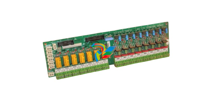 531X307LTBAFG1 F31X307LTBA LAN I/O Terminal Board
 -
ABB AFS670 19" Ruggedized Switch AFS670-EREEDDDSSEEEEEEEPZYX05.1.0
-
 NI Controller for VXI VXIPC-871B
 -
 IS200EPMCH1GE Mark VIe Patch Cord Power Distribution Card
 -
 VMICPCI-7632-03310 IS215UCCAH3A 350-657362-003310J GE gas turbine system control processor board
 -
 WEA13-13 2508-21001 Control Module / I/O Board
 -
WES5120 2340-21004 Controller Main Module
-
 WES5120 2340-21006 Field Controller Master Unit Module
 -
WESDAC D20ME 18-MAR-13 Excitation Control Module
-
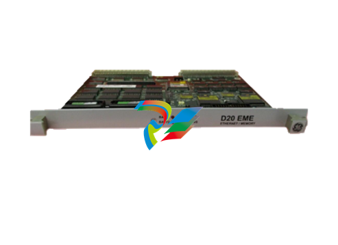
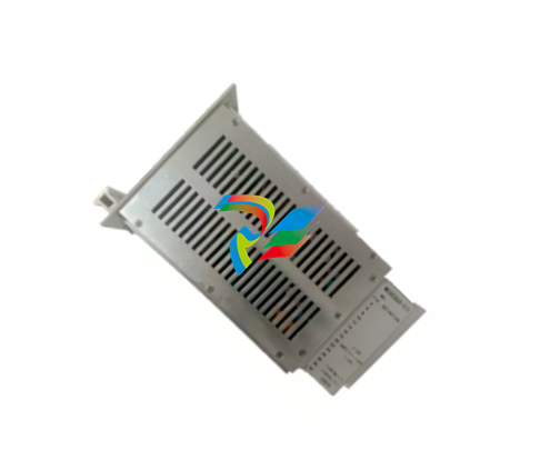
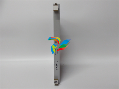 D20 EME 2400-21004 Ethernet communication and expansion module
 -
 GE DS3800XTFP1E1C Thyristor Fan Out Board Brand
 -
 GE SR745-W2-P1-G1-HI-A-L-R-E Feeder protection relay
 -
 GE IS230TNDSH2A Discrete Output Relay Module Brand
 -
 GE Fanuc IS200TDBSH2ACC Mark VI Terminal Board Brand
 -
 GE PMC-0247RC-282000 350-93750247-282000F Disk Drive
 -
GE PMC-0247RC-282000 350-93750247-282000F Disk Drive
-
 GE VMIVME-1150 Serial Communications Controller
 -
 GE VMIVME-5576 Fiber-Optic Reflective Memory with Interrupts
 -
GE VMIC Isolated Digital Output VMIVME-2170A
-
 GE MULTILIN 760 FEEDER MANAGEMENT RELAY 760-P5-G5-S5-HI-A20-R-E
 -
GE IS200AEPAH1BKE IS215WEPAH2BB Printed circuit board
-
 GE IS210BPPCH1A Mark VIe I/O Pack Processor Card
 -
 GE IS220PRTDH1A 336A4940CSP6 High-Performance RTD Input Module
 -
GE IS220PDIAH1BE 336A5026ADP4 Discrete Input Module
-
 GE IS420ESWBH3A IONET Switch Module
 -
 GE 516TX 336A4940DNP516TX 16-port Ethernet switch
 -
 GE EVMECNTM13 Embedded control module
 -
GE EVPBDP0001 EVPBDP032 control module
-
 GE Hydran M2-X Enhanced Monitoring with Extended Sensor Life
 -
 GE UR6CH Digital I/O Module
 -
 GE IC695CPU315-CD Central processing unit
 -
 GE 531X305NTBAMG1 DR Terminal Board
 -
 GE 531X305NTBALG1 NTB/3TB Terminal Board 531X Series
 -
 GE 531X305NTBAJG1 NTB/3TB Terminal Board.
 -
GE 531X305NTBAHG1 NTB/3TB Terminal Board 531X
-
 GE 531X305NTBAEG1 is a PCB that functions as a DR terminal board.
 -
General Electric 531X305NTBACG1 NTB/3TB Terminal Board 531X
-
 GE Digital Energy D20 Analog Input Module
 -
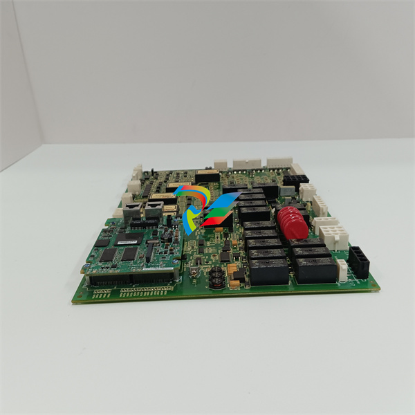
 GE 94-164136-001 main board Control board
 -
 GE 269 PLUS-D/O-100P-125V Digital motor relay
 -
 GALIL DMC-9940 High-performance motion controller
 -
FUJI NP1BS-08 base plate
-
 FUJI NP1Y32T09P1 Transistor drain type digital output module
 -
 FUJI NP1Y16R-08 Digital Output Module
 -
 FUJI NP1X3206-A High-speed digital input module
 -
 FUJI NP1AYH4I-MR current output module
 -
 FUJI NP1S-22 Power module redundancy
 -
 FUJI RPXD2150-1T servo drive module
 -
 FUJI FVR008E7S-2UX Ac frequency converter
 -
 FUJI Ac frequency converter FVR008E7S-2
 -
 FUJI FVR004G5B-2 Small general-purpose frequency converter
 -
 FUJI A50L-2001-0232 Industrial control module
 -
 FUJI A50L-001-0266#N High-performance servo amplifier
 -
 Honeywell FS7-2173-2RP Gas sensor
 -
 Honeywell 10106/2/1 Digital Input Module in Stock
 -
FRCE SYS68K CPU-40 B/16 PLC core processor module
-
Foxboro FBM I/O cards PBCO-D8-009
-
 Foxboro AD916AE Digital Control System (DCS) Module
 -
 GE SR750-P5-G5-S5-HI-A20-R-E Multilin Relay
 -
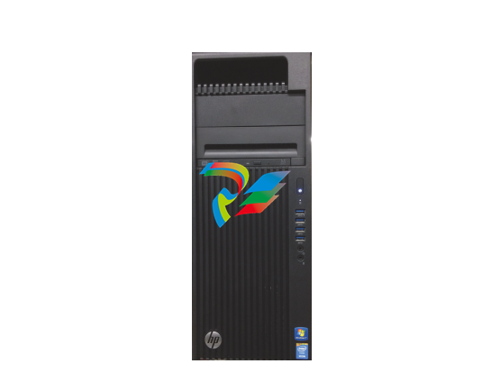
.jpg) FOXBORO H90 H90C9AA0117S Industrial Computer Workstation
FOXBORO H90 H90C9AA0117S Industrial Computer Workstation -
FOXBORO RH928AW | I/A Series Relay Output Module
-
.jpg) Foxboro N-2AX+DIO Multi-functional input/output module
Foxboro N-2AX+DIO Multi-functional input/output module -
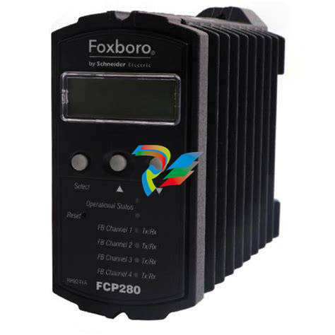 Foxboro RH924WA FCP280 Fiber Optic Network Adapter
 -
 FOXBORO H92 Versatile Hardware Component In
 -
 Foxboro FBM218 P0922VW HART® Communication Redundant Output Interface Module
 -
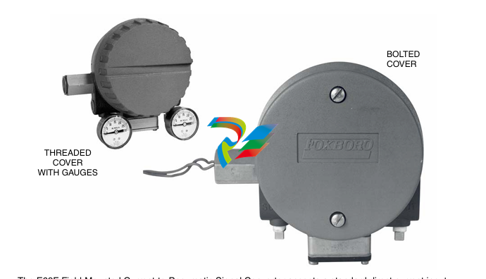
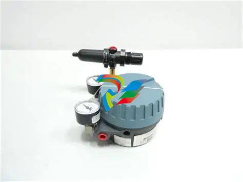
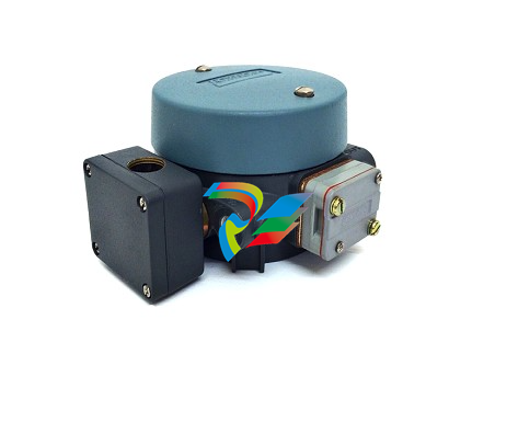 Foxboro E69F-TI2-J-R-S E69F Series Current-To-Pneumatic Signal Converter
 -
 Foxboro E69F-BI2-S Converter
 -
.jpg) Foxboro H92A049E0700 The host of the DCS control station
Foxboro H92A049E0700 The host of the DCS control station -
 Foxboro H90C9AA0117S Industrial computer workstation
 -
 Foxboro RH101AA High-performance industrial control module
 -
 Foxboro P0922YU FPS400-24 I/A Series Power supply
 -
.png) FOXBORO P0973LN Chassis-based managed switch with independent power supply
FOXBORO P0973LN Chassis-based managed switch with independent power supply -
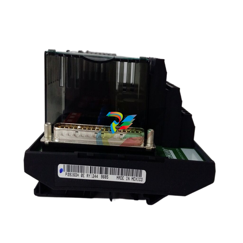
.jpg) FOXBORO P0926PA Input/output module
FOXBORO P0926PA Input/output module -
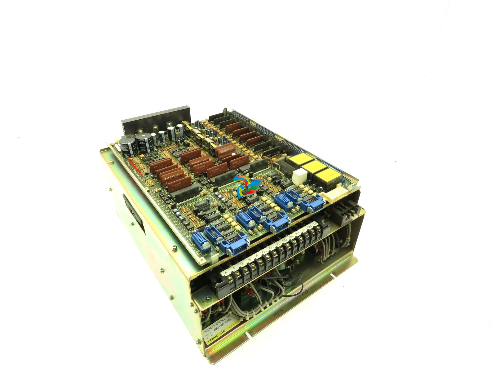 Fanuc A06B-6050-H402 3 AXIS ANALOG AC SERVO DRIVE
 -
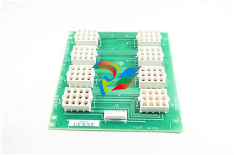
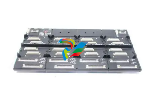
.jpg) FOXBORO L0130AD L0130AE-0H Power module group
FOXBORO L0130AD L0130AE-0H Power module group -
_lVjBYb.jpg) FOXBORO 0399085B 0303440C+0303458A Combination Control Module
FOXBORO 0399085B 0303440C+0303458A Combination Control Module -
 FOXBORO SY-0399095E (SY-0303451D+SY-0303460E) Process control board
 -
.jpg) FOXBORO 0399071D 0303440C+0303443B Input/Output (I/O) Module
FOXBORO 0399071D 0303440C+0303443B Input/Output (I/O) Module -
.jpg) FOXBORO RH924UQ Redundant Controller module
FOXBORO RH924UQ Redundant Controller module -
 FFOXBORO E69F-TI2-S current pneumatic converter
 -
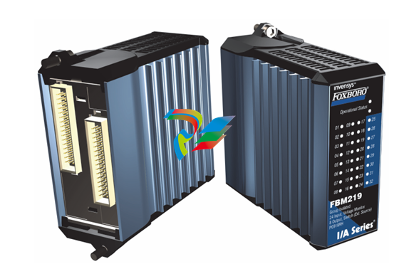 FOXBORO FBM219 RH916RH Discrete I/O Module
 -
 FOXBORO FBM227 P0927AC Module
 -
.jpg) FOXBORO 0399144 SY-0301059F SY-1025115C/SY-1025120E I/O module
FOXBORO 0399144 SY-0301059F SY-1025115C/SY-1025120E I/O module -
.jpg) FOXBORO SY-60399001R SY-60301001RB Industrial Control Module
FOXBORO SY-60399001R SY-60301001RB Industrial Control Module -
 FOXBORO 0399143 SY-0301060R SY-1025115C SY-1025120E Combined control board
 -
 FOXBORO 873EC-JIPFGZ electrodeless conductivity analyzer
 -
 FOXBORO P0916PH (High-density HART I/O Module)
 -
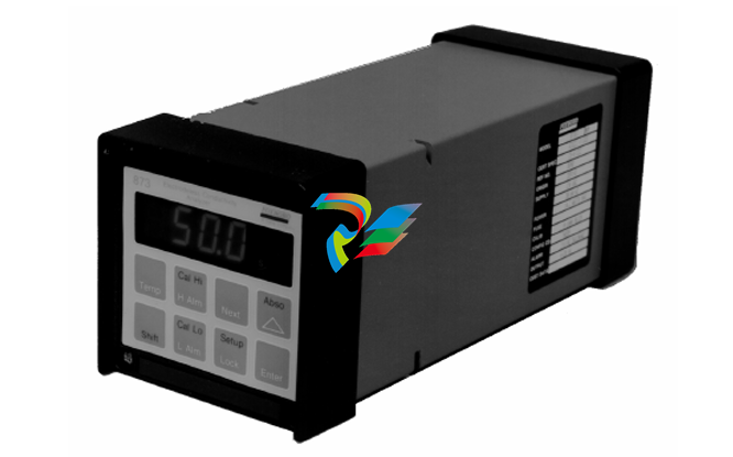
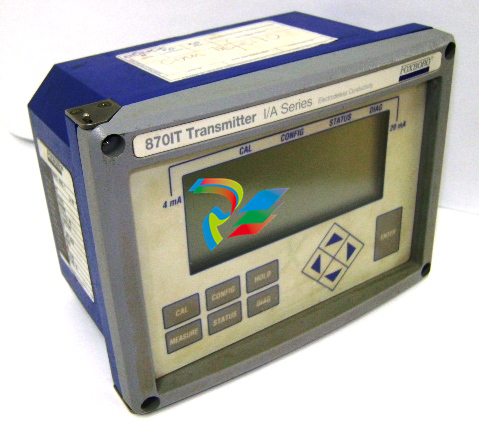 FOXBORO 870ITEC-AYFNZ-7 Intelligent Electrochemical Transmitters
 -
 FOXBORO Compact FBM240. Redundant with Readback, Discrete
 -
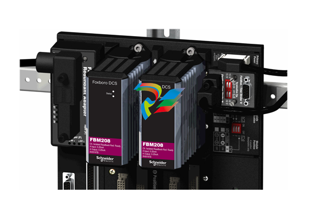 FOXBORO FBM208/b, Redundant with Readback, 0 to 20 mA I/O Module
 -
 FOXBORO FBM201e Analog Input (0 to 20 mA) Interface Modules


