
EMERSONWestinghouse Nuclear Automation
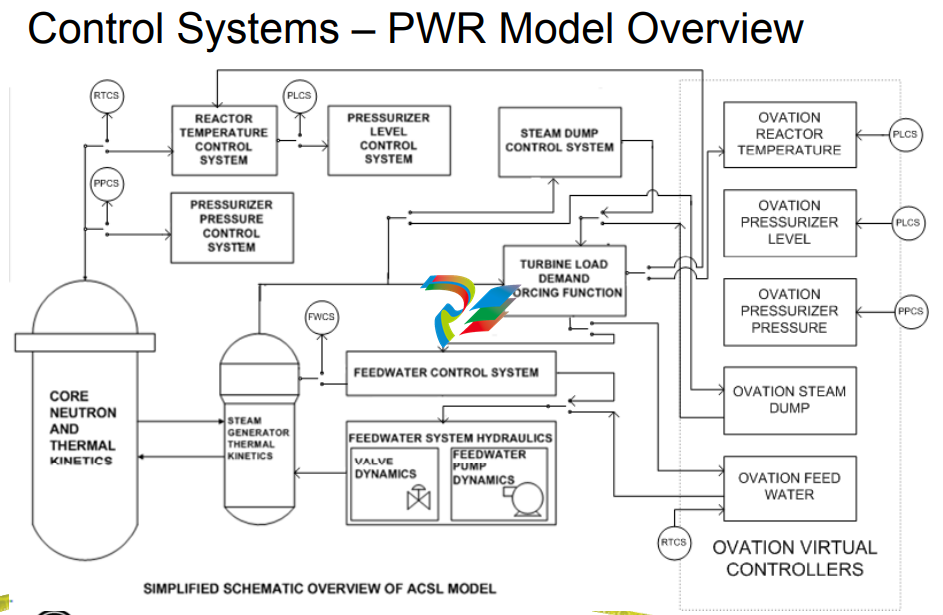
– Steam Dump or Steam Bypass – Reactor Pressure Regulation
– Feed System Feed System
– Steam System
– NSSS (core)
● Evaluation response over the full range of operation and
operational transient conditions
– Normal Operation
– Contingency Operations
● Provides high confidence set of initial tunings
● Pr
ovides
a basis for v
alidati
on
of desig
n
Feed Water Control Design Overview
- Example
● S/G Model Description Example
– Nodes of S/G Model
Feed Water Control Design Overview Example
Nodes of S/G Model
– Primary side tubes
– Secondary side tube bundle area (inside of wrapper)
– Riser section (from bundle exit through primary separators) Riser section (from bundle exit through primary separators)
– Upper downcomer (generally downcomer area from start of transition cone to top of primary separators)
– Lower downcomer (straight cylindrical portion of downcomer belo transition cone) below transition cone)
– Steam dome (region above top of risers or primary separators)
– Separate mass/energy balances for exit properties
– Momentum balance performed to calculate change in
various section flow rates
Feed Water Control Design Overview Feed Water Control Design Overview
- Example Example
● Proven Validation Approach
– SWIL (
S
oft
ware In
Loop) l d l lid ti t ti ) close
d loop valid
ation
testing
with plant specific model ensures realistic plant
operational response
–
ACSL Models validated for various SG’s and now
Reactor Vessels (BWR)
Westinghouse
B&W Canada (5 Units)
AREVA (5 Units)
C b ti E i i (4 U it ) Com
bustion
Eng
ineering (4
U
nits)
GE BWR 6 Reactor Vessel – Clinton and River Bend
Feed Water Control Design Overview Feed Water Control Design Overview
- Example Example
● Proven Control Application
– SWIL l d SWIL close
d
-l l oop, real-ti t ti id lid ti time
testing provides valid
ation,
allows integration test of graphics, alarms and controls with
plant operators before system is manufactured
Setpoints verified for operational transients
(determined previously with ACSL control system
models)
Dynamic set points (Gain, Integral & Derivative) for PID
are carefully chosen
For responsiveness to transients For responsiveness to transients
For near steady state conditions
Results in no tuning during plant startup
Software In Loop (SWIL) Software In Loop (SWIL)
● Upon completion of setpoint analyses, the ACSL plantspecific control model is switched to Ovation virtual
controllers for real-time, closed-loop validation testing
● Verifies delivered system contains the proper setpoints and
control logic as presented in the functional requirement
documents
● Test performed by Subject Matter Expert along with detailed
checks of control logic tuning to verify that setpoints match
the intended design
Feed Water Application (SWIL) Feed Water Application (SWIL)
● Validation of plant dynamic performance using transient test
scenariE l os;
Examples:
– Ramp Load Increase from 1% Power to Turbine Synchronization Power Level at 1%/min
– Turbine Synchronization and Initial Load Pickup
– T bi T i With t R t T i ( t i t l l) Turbine
Trip Without Reactor
Trip (at appropriate power level)
– 100% Power ±10% Load Swing
– 100% Power Ramp Load Decrease to 15% Power at 5%/min (bringing on various pumps at the
appropriate power)
– 1 % 100% %/ ( ff 15
% Power Ramp Load Increase to 100% Power at 5%/min (taking off various pumps at the
appropriate power level)
– Large Load Rejection (dependent upon plant design typically either 50 or 100% capability)
– Loss of One Feedwater Pump
– Level Setpoint Step at 5% Power
– Level Setpoint Step at 100% Power
– Level Setpoint Step at 50% Power with One Feedwater Pump Operating
– Level Set
point Ste
p at 50% Power with Two Feedwater Pum
ps O
peratin
g.
Feed Water Application Software (SWIL) Feed Water Application Software (SWIL)
● Key Customer representatives participate in testing:
– Operations, systems engineering, training, etc.
● Results of the testing (trend plots, Control Builder mark-ups,
and logbook entries) are collected into a test report and
archived.
● Upon successful completion of this testing, the application
software is ready for loading into simulator and FAT on
target plant hardware.
Westinghouse Test Plan Overview Westinghouse Test Plan Overview
● Covers validation test approach.
● Each test phase builds upon previous testing in an Each test phase builds upon previous testing in an
overlapping, structured approach in the order listed below:
1. Initial Software Debug Tests
2. Testing of Application Software (includes dynamic SWIL tests)
3. Simulator Testing
4. FAT 1: Target Hardware (power up, controller/network FAT 1: Target Hardware (power up, controller/network
redundancy failover & I/O checkout)
5. FAT 2: Base System Hardware/software (network, OWS, EWS,
AVS Domain workstation and system security configurations AVS, Domain workstation and system security configurations
6. FAT 3: Including signal validation, graphics, hardware alarms
output redundancy and application hardware )
7 Site Testing site acceptance tests and po er ascension test
-
 AMAT 0100-00046 AC Current Sense PWB
 -
 AMAT A0414720 Precision Advanced System Controller
 -
 AMAT 0010-00017 Precision Semiconductor Process Interface
 -
 AMAT 01-82889-00 High-Performance Semiconductor Component
 -
 ABB Sample Gas Cooler SCC-C 23070-0-10232110
 -
 IBA ibaRackline-PCHD Efficient process analysis with ibaHD-Server
 -
IBA ibaRackline-PC CAM Frame-accurate video information with ibaCapture
-
IBA ibaRackline-PC Highly available and reliable
-
 IBA Optical Signal Multiplier ibaBM-FOX-i-3o-D
 -
 IBA Optical Data Distribution System ibaBM-DIS-i-8o
 -
IBA Optical Data Concentrator ibaBM-COL-8i-o
-
 IBA ibaNet750-BM-D Acquisition via FO
 -
 IBA ibaW-750 Acquisition via Ethernet
 -
 IBA ibaPADU-8AI-I Compact Measurement Modules
 -
 IBA ibaPADU-D-8AI-I Compact Measurement Modules
 -
 IBA ibaPADU-8AI-U Compact Measurement Modules
 -
 IBA ibaPADU-D-8AI-U Compact Measurement Modules
 -
 IBA ibaPADU-4-AI-U Compact Measurement Modules
 -
 IBA ibaPADU-C-8AI Self-Supplied Data Logger
 -
 IBA ibaBM-ENetIP Bus monitor for EtherNet/IP
 -
 IBA ibaBM-eCAT Bus monitor for EtherCAT
 -
 IBA ibaBM-DP Bus monitor for PROFIBUS
 -
 IBA ibaBM-PN: Bus monitor for PROFINET IO
 -
 IBA ibaMS3xAI-1A Precision AC Current Measurement Module
 -
 IBA ibaDAQ Intelligent Central Unit
 -
 IBA ibaPQU-S Power Quality Monitoring System
 -
 IBA ibaCMU-S Condition Monitoring Unit (CMU)
 -
 IBA ibaPADU-S-IT-2x16 Modular data acquisition and control system
 -
IBA ibaPADU-S-CM Modular data acquisition system
-
 IBA ibaM-4AI-IEPE Input module
 -
IBA ibaM-4AI-UI Input module
-
IBA ibaM-4AI-150V-AC Input module
-
 IBA ibaM-4AI-600V-AC Input module
 -
 IBA ibaLink-SM-256V: High-Density PLC Data Interface
 -
 IBA ibaLink-SM-64V High-Performance S5/S7 Interface
 -
IBA ibaLink-SM-128V-i-2o Synchronous Fiber Optic (ibaNet)
-
 IBA ibaLink-SM-128V communication module
 -
IBA ibaM-4AI-5A-150A-AC Input module
-
 IBA ibaM-FO-2IO Interface module
 -
 IBA ibaM-COM Communication module
 -
 IBA ibaM-DAQ Intelligent Processor Module
 -
 B&R ECE161-0 MULTI digital input module
 -
 B&R ECCP70-01 MULTI CPU type B 42 KByte SRAM
 -
 B&R ECCP60-01 MULTI CPU type B 42 KByte SRAM
 -
 B&R DI426 digital input module
 -
 B&R 2DS100.60-1 electronic drum sequencer Absolut encoder
 -
 B&R 2CP100.60-1 CPU MODULE
 -
 B&R 2BM100.9 High-performance I/O module
 -
 AMAT 0190-14928 SCR Power Controller (PVD Reverse Zone)
 -
 AMAT 0500-01065 300mm Loadlock Interface Interlock Board
 -
 AMAT 2000-21123 Advanced Vacuum Seal Assembly
 -
 AMAT 0660-00090 High-Performance Industrial Power Filter
 -
 AMAT 0240-34077 Centura Endpoint Controller Kit
 -
 AMAT 0195-10215 High-Precision Pedestal Assembly
 -
 AMAT 0190-76050 VGA Video Controller VME Module
 -
 AMAT 0190-75084 High-Performance Communication & Logic Controller
 -
 AMAT 0190-60287 Precision VME/cPCI Interface Control Module
 -
 AMAT 0190-53752 DI Water I/O Controller PCB
 -
 AMAT 0190-37993 DeviceNet Scanner Pro (3U CompactPCI)
 -
 AMAT 0190-37833 MKS CDN500R-5 EPI 300mm Interface Module
 -
AMAT 0190-37771 MKS CDN500R Interlock Control Module
-
 AMAT 0190-37616 High-Precision Analog Input/Output Interface
 -
 AMAT 0190-36787B ISAC CP I/O Block 2 (Top) - Revision B
 -
 AMAT 0190-36787 ISAC CP I/O Block 2 (Top)
 -
AMAT 0190-36511 DIP294 DeviceNet I/O Control Block
-
 AMAT 0190-35764 & 0190-35765: Precision Control Interface Duo
 -
 AMAT 0190-35763 High-Performance Integrated Power Module
 -
 Applied Materials (AMAT) 0190-34512 4-Channel DeviceNet Scanner Interface
 -
 Applied Materials (AMAT) 0190-34282 High-Stability Process Control Module
 -
Applied Materials (AMAT) 0190-27707 High-Precision DeviceNet I/O Controller
-
 Applied Materials (AMAT) 0190-27072 High-Performance Semiconductor Interface
 -
 AMAT 0190-24007 CPCI-3720CF Single Board Computer
 -
 AMAT 0190-23905 Spellman ESC High Voltage Power Supply
 -
 AMAT 0190-22967 High-Density Analog I/O Control Board
 -
 AMAT 0190-22543 High-Precision Analog Input/Output Module
 -
 AMAT 0190-17964 Etch DPS Interlock Module
 -
 AMAT 0190-17894 Interlock Module Conductor HART
 -
 AMAT 0190-17081 2U CompactPCI System Host Processor
 -
 AMAT 0190-16926 and 0190-16928 Based on Compact PCI
 -
AMAT 0190-15915 Intelligent I/O Control Module
-
 AMAT 0190-15840 4-Port UPA DeviceNet Interface Module
 -
 AMAT 0190-15384 Advanced Digital Signal Interface Module
 -
 AMAT 0190-14027 Wafer Flat Finder PCB
 -
 AMAT 0190-12695 SBS CL7 3U CompactPCI Single Board Computer
 -
 AMAT 0190-11817 CP3-SER16-TTL 16-Port Serial Interface Card
 -
 AMAT 0190-11524 CDN500-25 Interlock Module
 -
 AMAT 0190-07450 CompactPCI 48-Channel Digital I/O Interface Board
 -
 AMAT 0190-05990-001 Maglev Rotation System Controller (300mm)
 -
 AMAT 0190-05647 LK3710 Serial Module Transition Card
 -
 AMAT 0190-04457 High-Performance Integrated Circuit Control Module
 -
 Applied Materials (AMAT) 0190-04098 | 5.X Factory Interface I/O Distribution Board
 -
 Applied Materials (AMAT) 0190-03705 | MF Producer SE/E Interlock Module
 -
 Applied Materials (AMAT) 0190-02748 | Flex Scanner Transition Module
 -
 Applied Materials (AMAT) 0190-02362 | Mainframe Interlock 1 Relay Module
 -
 Applied Materials (AMAT) 0190-01227 | Intelligent Motor Control OMS Board
 -
 Applied Materials (AMAT) 0190-00318 | VME 486 Video Controller
 -
 Applied Materials (AMAT) 0130-14007 | Advanced RF Signal Assembly
 -
 Applied Materials (AMAT) 0130-14005 | RF Cable/Interface Assembly
 -
 Applied Materials (AMAT) 0130-01218 | High-Efficiency RF Interface Controller
 -
 Applied Materials (AMAT) 0110-77040 | Head Pneumatic Controller
 -
 Applied Materials (AMAT) 0110-00077 | Precision Control Module
 -
 AMAT 0101-57015 high-performance Next-Generation Deflection Amplifier Board
 -
 AMAT 0100-77040 critical Head Pneumatic Controller Board
 -
 AMAT 0100-76291 Data Buffer / Memory Expansion Interface
 -
 AMAT 0100-76290 Advanced I/O Interface Board
 -
 AMAT 0100-76269 Control Board / Interface Module
 -
 AMAT 0100-71462-01 high-performance Process Controller PCB
 -
 AMAT 0100-71171 Chamber Interlock Control PCB
 -
 AMAT 0100-71154 Semiconductor Circuit Board / Electronic Group Card
 -
 AMAT 0100-70034 PCB Assembly (PCBA) for Endpoint VGA I/O Interconnect.
 -
 AMAT 0100-38032 ESC (Electrostatic Chuck) Controller PCB
 -
 AMAT 0100-36035 DPS Source Match / Seriplex I/O Distribution PCB
 -
 AMAT 0100-35231 Seriplex I/O Distribution Module
 -
 AMAT 0100-35217 TC Amp Interlock PCB Module
 -
 AMAT 0100-35065 High-Precision Serial Isolator PCB
 -
 AMAT 0100-35054 Advanced Chamber Interface Module
 -
 AMAT 0100-20453 DeviceNet Digital I/O Interface Board
 -
 AMAT 0100-20100 High-Performance Semiconductor Component
 -
 AMAT 0100-20068 Precision CCD Image Control Board
 -
 AMAT 0100-20064 Advanced Semiconductor Control Module
 -
Applied Materials (AMAT) 0100-20018 Advanced Communication Interface Module
-
 Applied Materials (AMAT) 0100-20016 High-Performance Interface and Control Module
 -
 Applied Materials (AMAT) 0100-20003 Digital I/O (DI/DO) Interface Board
 -
 Applied Materials (AMAT) 0100-20001 System Electronics Interface (SEI) / PCB Assembly
 -
 Applied Materials (AMAT) 0100-11030 Chamber Hardware / Gas Distribution Component
 -
 Applied Materials (AMAT) 0100-11022 Semiconductor Board Card
 -
 Applied Materials (AMAT) 0100-11018 Advanced Interface Control Module
 -
 Applied Materials (AMAT) 0100-11001 Precision Analog Output Board


