
EMERSONWestinghouse Nuclear Automation
25
. Site Testing
– site acceptance tests and po
wer ascension test
Feed Water (FW) Control Systems Feed Water (FW) Control Systems
In delivering digital FW control systems,
W ti h li Westing
house applies:
• High Quality Application Software Development
Process
– Software Requirements Document
– Software Description Document
– S ft Lif l Pl S
oftware Lifecycle Plan
– Failure Modes and Affects Analysis (software and hardware)
– Software Hazards Analysis
– P i t t ith 10CFR50 A di B Processes consis
ten
t with 10CFR50
Appendix
B
where commercial grade application software can be
applied in critical applications
Feed Water (FW) Control Systems Feed Water (FW) Control Systems
Westinghouse NA uses “defense in design” to
ens re deli er of a high q alit prod ct ens
ure deli
very of
a high
q
uality prod
uct:
• Plant Specific Models and validation testing with application in closed
loop demonstrates deterministic behavior of the application early in
d i es gn process
• Applications are partitioned on controllers such as not to cause failures
that could add positive reactivity or effect plant design basis
• Reliance on the control network is limited Reliance on the control network is limited
– controllers and associated controllers and associated
I/O can continue to function with loss of network
• I/O designed on controller loss to revert to known or benign state
• For critical control component, a hard control station is provided to For critical control component,
a hard control station is provided to
operator manual control – another layer of redundancy
• Redundancy of system components at all levels
Existing Analog Feed Water Control Existing Analog Feed Water Control
● Historically, Steam Generator Water Level has
been difficult to contro
l
– Analog-based systems are limited
– Per INPO data; second leading system for plant trip
– Steam Generator (SG) shrink and swell phenomena
– Steam & Steam
& feedwater feedwater measurement unreliable at low power levels measurement unreliable at low power levels
– Manual control with multiple operators required to bring up unit
– Prone to single points of failure
Analog Inputs – no active redundancy
Manual operator action in detecting input failures
Modulating Outputs single driver card
29
Modulating Outputs
– single driver card
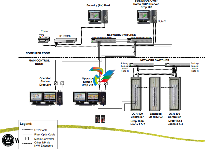
Typical Advanced Digital Feed Water
System (ADFCS) Configuration System (ADFCS) Configuration
● 1,2, 3 or 4 Redundant Controllers:
● HMI -T O t W k t ti ith ft t l Two
Opera
tor
Wor
k
s
t
ations with soft con
trols
– M/A Stations for FW Valve & FP Controls
● One Engineer One Engineer s/Data ’s/Data Base Server Workstation Base Server Workstation
● Network Equipment – Fast Ethernet Switches
● Anti-virus Station
● New Cabinets or retrofit of existing cabinets
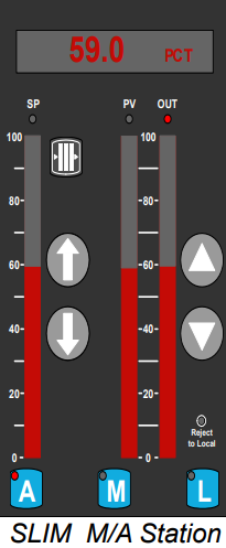
● SLIM M/A’s for Main, Bypass and Feed Pumps
ADFCS
– Main Control Room Main Control Room
● Redundant operator stations & LCD
displays in MCR displays in MCR 59 0 PCT
● SLIM M/A’s for all modulating valves, &
feed pumps
Add d l f d d
59.0 PCT
100
SP PV OUT
100
Add
e
d layer o
f re
dun
dancy upon
controller failure
Works seamlessly with soft control
80
60 60
80
● Remove signal selector switches
● Remove select recorders – steam/feed
water, wide and narrow ran
ge level 20
40
20
40
, g
● Remove individual channel indicators &
replace with median
● Select indicators can remain
“live
”
Typical ADFCS Architecture Typical ADFCS Architecture
ADFCS
– Design Overview Design Overview
● Improved system reliability via signal selectors
– Narrow Range Level
– Wide Range Level
– Feedwater Flow
– Steam Flow
– Steam Pressure
– Feedwater Tem
perature
– Turbine Impulse Pressure or Nuclear Power
– Feedwater Header Pressure
( ) FP turbine runback)
● Improve System performance by integrating feed pump governor controls
ADFCS
– Design Overview Design Overview
● Proven Control Application – third generation
design consistent with AP1000 design consistent with AP1000
– Low and High Power Controllers
Bumpless Transfer between Low Power and High
P C t lM d Power
Con
tro
l
M
o
de
– Feedwater Temperature Compensation
Low Power Level Controller gain & reset adjusted Low Power Level Controller gain
& reset adjusted
based on feedwater temperature
Compensates for the effects of shrink and swell in
ll t eve
l response
to fd t ee
dwa
ter fl i ti flow variations
– High Power Level Controller proportional gain and
integral time adjusted based on steam flow
35
integral time adjusted based on steam flow
ADFCS
– Design Overview Design Overview
● Proven Control Application (cont’d)
– Load Index Load Index
Wide Range Level
Anticipates need for flow change at low power
– Automatic transition from bypass valve to main feed Automatic transition from bypass valve to main feed water regulation valve
– Capability of operating with one valve in manual and other in auto other in auto
– Control Valve Linearization & Performance
Compensates for non-linearities in valve characteristics and ensures an effective and stable
control response
Position feedback provides means to detect sticking or sluggish valve response and alert the operator
-
 Hirschmann RS20-1600M2T1SDAEHH03.1.02 Rail Switch
 -
 Hirschmann BRS30-24TX Industrial Rail Switch
 -
 Hirschmann RSPM20-4T14T1EV9HHS999.9.99 Managed Ethernet Switch
 -
 Hirschmann BELDEN RS40-0009CCCCSDAPHH09.0.14 / RS400009CCCCSDAPHH09014
 -
Hirschmann RS40 Rail Switch RS40-0009CCCCSDAE
-
 Hirschmann BELDEN RS30-0802T1T1SDAP / RS300802T1T1SDAP Fully Managed Layer 2 Compact Rail Switch
 -
 Hirschmann BELDEN RS20-0800M2M2SDAUHH / RS200800M2M2SDAUHH
 -
 Hirschmann EAGLE30-04022O6TT999SCCY9HSE3F Industrial Firewall Router Switch
 -
 Hirschmann RS20-1600T1T1SDAEHH09.0.14 RS20 Rail Mount Ethernet Switch
 -
 Hirschmann EAGLE0200T1T1TDDY90000HHE05.3.03 Industrial Security Router
 -
Hirschmann - BELDEN MIPP-AD-1L9P
-
 HIRSCHMANN RSPM20-4Z64Z6TV9HHS9 942 106-999 RAIL SAFETY SWITCH
 -
 HIRSCHMANN FIBEROPTIC MODULE FIP P/N: OZDFIPG3T
 -
 HIRSCHMANN RS20-1600M2M2SDAUHH Ethernet rack-mounted switch
 -
 HIRSCHMANN BELDEN RS20-0400T1T1SDAEHH04.0.01 / RS200400T1T1SDAEHH04001
 -
HIRSCHMANN MM2-4FXM3 MICE Media Module
-
HIRSCHMANN RS20-0800M2M2SDAE Industrial Ethernet Rail Switch
-
 Hirschmann RS20-2400T1T1SDAP / RS20-2400T1T1SDAPHH05.0.02
 -
 GE MLJ1005B010H00C MLJ Digital Synchromism Check
 -
 ALSTOM MICROTECH DX21-M2 Digital Excitation Controller
 -
HIRSCHMANN BRS20-1200ZZZZ-STCY99HHSES
-
 HIRSCHMANN MM3-4FXM2 MICE Media Module
 -
Hirschmann RSB20-0800T1T1SAABHH 8Port ENet Rail Switch RSB20
-
 Hirschmann MACH102-8TP Ethernet Switch
 -
 SAACKE DDZ-M marine steam pressure atomizer
 -
 SAACKE SKV-A marine rotary cup atomizer
 -
 SAACKE Seavis HMI05e
 -
 Kollmorgen MMC-SD-2.0-230 Servo Drive 100-240VAC 2KW 10A Output 3PH 100-240VAC
 -
 Kollmorgen Servo drive CR10550
 -
 Kollmorgen AKD-P01207-NACN-0054 Servo Driver
 -
 Kollmorgen S406M-CA-036 Servostar
 -
.png) Kollmorgen AKD-B02407-NAAN-0000 Digital Servo Drive
Kollmorgen AKD-B02407-NAAN-0000 Digital Servo Drive -
 Kollmorgen SERVOSTAR S406AM-CA Digital Servo Drive
 -
 KOLLMORGEN SERVOSTAR 603-AS SERVO AMPLIFIER_SERVOSTAR603AS_S60301
 -
Kollmorgen S700 Servo Controller (S70602-NANANA-NA)
-
 Kollmorgen MPK411 controller
 -
 KOLLMORGEN MMC-SD-1.3-460-D Smart Drive
 -
 KOLLMORGEN AKM21C-CKB2AA-00 / AKM21CCKB2AA00 Servomotor
 -
 BECKHOFF AX5106-0000-0200 | Digital Compact Servo Drives 1-channel
 -
 BECKHOFF C3620-0000 INDUSTRIAL COMPUTER (MOTORSHELVES)
 -
 Beckhoff EK1960-0000 TwinSAFE Compact Controller
 -
 Beckhoff C6930-0050 Control Cabinet Industrial PC
 -
 Beckhoff CP7711-0001-0030 Industrial Computer Detection
 -
 Beckhoff CX1001-0111 Embedded PC CPU Module
 -
 Beckhoff C6017-0020 | Ultra-compact Industrial PC
 -
 Beckhoff EK1322 | 2-port EtherCAT P junction with feed-in
 -
 Beckhoff CP2219-0010 Panel
 -
 BECKHOFF C6015-0020 ULTRA COMPACT INDUSTRIAL PC
 -
 BECKHOFF CX2030-0120/Standard CPU Module Embedded PC Windows PLC controller
 -
 Beckhoff CP7721-1090-0020 Panel PC
 -
 Beckhoff PC CPU Module CX5130-0175
 -
 Beckhoff C6920-0050 Control Cabinet
 -
 Beckhoff EL6631 EtherCAT 2-Port Communication Interface, Profinet RT Controller
 -
 Beckhoff CP6202-0001-0060 touch screen panel PC
 -
 Beckhoff CP3916-1002-0000 Multi-Touch Control Panel
 -
 Beckhoff EP1809-0021 | EtherCAT Box, 16-channel digital input, 24 V DC, 3 ms, M8Preferred type
 -
 Beckhoff CX8190 PLC Embedded Industrial PC Ethernet Controller
 -
 Beckhoff CX2100-0914 Power Supply for External
 -
 Beckhoff Automation CP6906-0001-0000 HMI
 -
 Beckhoff EP7342-0002 Module
 -
 Beckhoff CX1020-0112 / CX1100-0910 / CX1020-N010 / CX1100-0003 Windows CPU
 -
 Beckhoff EP7211-0034 EtherCAT Box 1 Channel Motion Interface
 -
 Beckhoff C6240-0030 Control cabinet Industrial PC
 -
 beckhoff motherboard CB1052-0004 CB1052-0004
 -
 Beckhoff AX2006-AS Servo Drive / Variable Frequency Drive
 -
BECKHOFF CP6207-0001-0020 NSMP
-
 Beckhoff C6930-1142-0060 Industrial Computer
 -
 Beckhoff FC7501-0000 interface card
 -
 Beckhoff CX5140-0175 Embedded PC PLC CPU CX5140 Industrial Controller
 -
 Beckhoff CP7802-1100-0010: High-End IP65 Control Panel with DVI/USB Extended Interface
 -
BECKHOFF CP3716-1058-0010 CONTROL PANEL
-
 Beckhoff AX8108-0000 Single-Axis Module
 -
 Beckhoff CU8851-0000 | USB extension, USB Extended 2.0 receiver box
 -
Beckhoff C6017-0030 | Ultra-compact Industrial PC
-
 Beckhoff CX1001-0120/CX10010120.cx1000-n001.cx1000-n000 System Overview
 -
 Beckhoff CPU Module CX5140-0155/4GB CPU Module
 -
 Beckhoff CP6533-0001-005: Built-in Panel PC with High-Definition Multi-Touch Control
 -
 Beckhoff EL5042 | EtherCAT Terminal, 2-channel encoder interface, BiSS® C
 -
 Beckhoff C6920-1080-0040: Premium Control Cabinet Industrial PC
 -
 Beckhoff C6920-0060 | Control cabinet Industrial PC
 -
 Beckhoff Embedded-PC CX5010-1121
 -
 Beckhoff CB3050-0010 Mainboard Motherboard
 -
 Beckhoff PLC module CX1020-0000 Basic CPU module (service phase)
 -
 Beckhoff CP7812-1056-0010 15" Multitouch Display Control Panel
 -
 Beckhoff CX5120-0115 /2GB Controller Module
 -
 Beckhoff CP7201-1000-0000 Industrial Panel PC
 -
 Beckhoff Servo Motor AM8061-0JH1-0000
 -
 BECKHOFF CP6503-0001-0050 Built-in Panel PC
 -
Beckhoff CP3919-0010 Display G190ETN01.2 19" PCT V04. Multi-touch Control Panel
-
 Beckhoff CX5110-0112-9020/000368201 Embedded PC Intel Atom Processor
 -
 Beckhoff AX8206-0000 Dual-Axis Module
 -
Beckhoff Nail Operating Terminal CP7032-1031-0010
-
Beckhoff AM8042-0EH1-0000 Servomotor 4.10 Nm (M0), F4 (87 mm)
-
 Beckhoff EK9300 Beckhoff CPU Module
 -
Beckhoff CP3224-0020 Multitouch-Panel-PC
-
 Beckhoff CP2712-0000 12.1" 24VDC Touch Screen WMD0
 -
 BECKHOFF CX5240-0195 / 0000289234 Embedded PC 40 GB CFast Card
 -
 Beckhoff CP6932-1000-0000 Control Panel
 -
 BECKHOFF CX5120-0121 PLC Module
 -
 Beckhoff EL3218 | EtherCAT Terminal, 8-channel analog input
 -
Beckhoff C6640-0050 | Control cabinet Industrial PC
-
 Beckhoff Cx5130-0120/4GB Embedded-PC
 -
 BECKHOFF CX2030-0122 PLC PROCESSOR
 -
 BECKHOFF CX5020-0122 Controller Module
 -
 Beckhoff CP3915-0000 Multitouch Panel
 -
 BECKHOFF EL3014 | EtherCAT Terminal
 -
 BECKHOFF Industrial Computer c6920-1057-0030
 -
 Beckhoff CX5130-0141/4GB CX5130-0141 Embedded PC
 -
 Beckhoff C6240-1052-0040 4-086-06-3073 Industrial Computer
 -
 Beckhoff CX5140-0135 /4GB High-Performance Embedded Industrial PC
 -
 Beckhoff C6515-1001-0000 Industrial PC
 -
 Beckhoff AX5103-0000-0200 - Digital Compact Servo Drives
 -
 Beckhoff CX2030-0130-1003/4GB Basic CPU module
 -
 Beckhoff AX8620-0000 Power Supply Module
 -
 Beckhoff CX9020-0111 module with
 -
 Beckhoff EL7332 PLC Module
 -
 BECKHOFF CP7709-0001-0020 HMI
 -
 Beckhoff CX5120-0155/2GB Embedded PC
 -
 BECKHOFF CP7037-1037-0010 OPERATOR INTERFACE TOUCHSCREEN
 -
 Beckhoff EK9000 | ModbusTCP/UDP Bus Coupler
 -
 Beckhoff Touch Panel Screen CP6020 -0000-0000
 -
 Beckhoff CX2020-0121 Module FAST Shipping
 -
 Beckhoff CX2030-0125 Basic CPU Module
 -
 Beckhoff CP3918-0000 Multi-Touch 18.5" Control Panel
 -
 Automotion LC4A00010 DC BL Motor Control, ATS, Sub Assy, SCP, 115VAC,
 -
 500T-115VAC - VAS ENGINEERING - DORIC 500 SERIES DIGITAL TEMP INDICATOR
 -
 Honeywell X-DCS2000/EN Digital Integrated System Manager 50/60Hz 100-240V #4
 -
 Kollmorgen S60600 Servostar600 606-Fan 4 kVA, 6 A, 3 X 230 - 480 V


