
ABBElectro-Pneumatic Positioner TZIDC
- position out of the adjusted range
- positioning time-out (adjustable time parameter)
- position controller inactive
- counter limits (settable in the diagnosis phase) exceeded
While automatic commissioning is in progress, the current state is
continuously indicated on the integrated LCD.
During operation, the LCD shows the most important process
variables:
- current position (in %),
- malfunctions, alarms, messages (as code)
Access to extended monitoring parameters is possible via HART
communication and the DTM.
3.1.4 Diagnosis parameters
Pos: 7.13 /Technische Daten / Datenblatt/Aktorik/Stellungsregler/Allgemein/Betrieb/Diagnoseparameter @ 10mod_1176214500906_3101.doc @ 77406
The diagnosis parameters of the TZIDC program inform the operator
about the operating conditions of the valve.
From this information the operator can derive which maintenance
works are required, and when.
Additionally, limit values can be defined for these parameters. When
they are exceeded, an alarm is reported.
The following values are e.g. determined:
- Number of movements performed by the valve
- Total travel
The diagnosis parameters and limit values can be called up, set, and
reset via HART communication, using the configuration program.
Pos: 7.14 /Überschriften/1.1/2-spaltig/Bedienpanel @ 10mod_1176214143953_3101.doc @ 77229
3.2 Operator panel Pos: 7.15 /Technische Daten / Datenblatt/Aktorik/Stellungsregler/Allgemein/Betrieb/Bedienpanel TZIDC-1x0 @ 10mod_1176214815500_3101.doc @ 77427
The TZIDC positioner’s operator panel with four pushbuttons allows
for
- operational monitoring
- manual control
- configuration
- fully automatic commissioning
The operator panel is protected by a cover which avoids
unauthorized access to the operating elements.
Pos: 7.16 /======= Spaltenumbruch ======== @ 0mod_1132937966324_3101.doc @ 3831
Pos: 7.17 /Überschriften/1.1.1/2-spaltig/Ein-Tasten-Inbetriebnahme @ 10mod_1176214193156_3101.doc @ 77250
3.2.1 Single-button commissioning
Pos: 7.18 /Technische Daten / Datenblatt/Aktorik/Stellungsregler/TZIDC / TZIDC-200/Betrieb/Ein-Tasten-Inbetriebnahme @ 10mod_1176214842843_3101.doc @ 77448
Commissioning the TZIDC positioner is especially easy. The
standard Autoadjust function for automatic adaptation of the device
parameters can be started by simply pressing a single front panel
button, and without knowing parameterization details.
Depending on the selected actuator type (linear or rotary), the
displayed zero position is automatically adapted:
- for linear actuators counter-clockwise (CTCLOCKW)
- for rotary actuators clockwise (CLOCKW).
Besides this standard function, a customized “Autoadjust” function is
available. The function is launched either via the operator’s panel or
HART communication.
Pos: 7.19 /Überschriften/1.1.1/2-spaltig/Anzeigen @ 10mod_1176214259859_3101.doc @ 77271
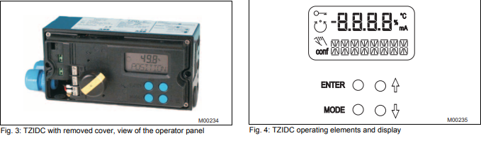
3.2.2 Display
Pos: 7.20 /Technische Daten / Datenblatt/Aktorik/Stellungsregler/TZIDC / TZIDC-200/Betrieb/Anzeigen @ 10mod_1176214873937_3101.doc @ 77469
The information indicated by the 2-line LC display is permanently
updated and adapted during operation, to inform the operator in an
optimal way.
During control operation (control with or without adaptation) the
following TZIDC data can be called up by pressing the pushbuttons
briefly:
- Up button: Current setpoint (mA)
- Down button: Temperature in device
- Up + Down buttons: Current control deviation
4 Communication Pos: 9.2 /==== Wechsel ein- auf zweispaltig ==== @ 0mod_1130421847171_3101.doc @ 3828
Wechsel ein-auf zweispaltig Pos: 9.3 /Überschriften/1.1/2-spaltig/DTM @ 10mod_1176215310421_3101.doc @ 77511
4.1 DTM Pos: 9.4 /Technische Daten / Datenblatt/Aktorik/Stellungsregler/TZIDC / TZIDC-200/Kommunikation/DTM @ 10mod_1176215507046_3101.doc @ 77595
The DTM (Device Type Manager) for TZIDC is based on the
FDT/DTM technology (FDT 1.2) and can be integrated in a process
control system or loaded in a PC with the DSV401 (SMART VISION)
program. This allows you to work with the same user interface in the
commissioning phase, during operation, and for service tasks for
monitoring the device, setting parameters, and uploading data.
Communication is based on the HART protocol. It occurs via a local
interface connection (LKS) or in frequency-modulated mode using an
FSK-modem connected at any chosen point of the 20 mA signal line.
Communication has no effect on operation. Newly set parameters are
saved in the non-volatile memory directly upon the download into the
device, and become active immediately.
Pos: 9.5 /Überschriften/1.1/2-spaltig/LKS-Adapter (RS-232 Schnittstellenwandler) @ 10mod_1176215338250_3101.doc @ 77532
4.2 LKS adapter (RS-232 interface converter) Pos: 9.6 /Technische Daten / Datenblatt/Aktorik/Stellungsregler/TZIDC / TZIDC-200/Kommunikation/LKS-Adapter (RS-232 Schnittstellenwandler) @ 10mod_1176215612828_3101.doc @ 77616
-
 Applied Materials (AMAT) 0190-34512 4-Channel DeviceNet Scanner Interface
 -
 Applied Materials (AMAT) 0190-34282 High-Stability Process Control Module
 -
Applied Materials (AMAT) 0190-27707 High-Precision DeviceNet I/O Controller
-
 Applied Materials (AMAT) 0190-27072 High-Performance Semiconductor Interface
 -
 AMAT 0190-24007 CPCI-3720CF Single Board Computer
 -
 AMAT 0190-23905 Spellman ESC High Voltage Power Supply
 -
 AMAT 0190-22967 High-Density Analog I/O Control Board
 -
 AMAT 0190-22543 High-Precision Analog Input/Output Module
 -
 AMAT 0190-17964 Etch DPS Interlock Module
 -
 AMAT 0190-17894 Interlock Module Conductor HART
 -
 AMAT 0190-17081 2U CompactPCI System Host Processor
 -
 AMAT 0190-16926 and 0190-16928 Based on Compact PCI
 -
AMAT 0190-15915 Intelligent I/O Control Module
-
 AMAT 0190-15840 4-Port UPA DeviceNet Interface Module
 -
 AMAT 0190-15384 Advanced Digital Signal Interface Module
 -
 AMAT 0190-14027 Wafer Flat Finder PCB
 -
 AMAT 0190-12695 SBS CL7 3U CompactPCI Single Board Computer
 -
 AMAT 0190-11817 CP3-SER16-TTL 16-Port Serial Interface Card
 -
 AMAT 0190-11524 CDN500-25 Interlock Module
 -
 AMAT 0190-07450 CompactPCI 48-Channel Digital I/O Interface Board
 -
 AMAT 0190-05990-001 Maglev Rotation System Controller (300mm)
 -
 AMAT 0190-05647 LK3710 Serial Module Transition Card
 -
 AMAT 0190-04457 High-Performance Integrated Circuit Control Module
 -
 Applied Materials (AMAT) 0190-04098 | 5.X Factory Interface I/O Distribution Board
 -
 Applied Materials (AMAT) 0190-03705 | MF Producer SE/E Interlock Module
 -
 Applied Materials (AMAT) 0190-02748 | Flex Scanner Transition Module
 -
 Applied Materials (AMAT) 0190-02362 | Mainframe Interlock 1 Relay Module
 -
 Applied Materials (AMAT) 0190-01227 | Intelligent Motor Control OMS Board
 -
 Applied Materials (AMAT) 0190-00318 | VME 486 Video Controller
 -
 Applied Materials (AMAT) 0130-14007 | Advanced RF Signal Assembly
 -
 Applied Materials (AMAT) 0130-14005 | RF Cable/Interface Assembly
 -
 Applied Materials (AMAT) 0130-01218 | High-Efficiency RF Interface Controller
 -
 Applied Materials (AMAT) 0110-77040 | Head Pneumatic Controller
 -
 Applied Materials (AMAT) 0110-00077 | Precision Control Module
 -
 AMAT 0101-57015 high-performance Next-Generation Deflection Amplifier Board
 -
 AMAT 0100-77040 critical Head Pneumatic Controller Board
 -
 AMAT 0100-76291 Data Buffer / Memory Expansion Interface
 -
 AMAT 0100-76290 Advanced I/O Interface Board
 -
 AMAT 0100-76269 Control Board / Interface Module
 -
 AMAT 0100-71462-01 high-performance Process Controller PCB
 -
 AMAT 0100-71171 Chamber Interlock Control PCB
 -
 AMAT 0100-71154 Semiconductor Circuit Board / Electronic Group Card
 -
 AMAT 0100-70034 PCB Assembly (PCBA) for Endpoint VGA I/O Interconnect.
 -
 AMAT 0100-38032 ESC (Electrostatic Chuck) Controller PCB
 -
 AMAT 0100-36035 DPS Source Match / Seriplex I/O Distribution PCB
 -
 AMAT 0100-35231 Seriplex I/O Distribution Module
 -
 AMAT 0100-35217 TC Amp Interlock PCB Module
 -
 AMAT 0100-35065 High-Precision Serial Isolator PCB
 -
 AMAT 0100-35054 Advanced Chamber Interface Module
 -
 AMAT 0100-20453 DeviceNet Digital I/O Interface Board
 -
 AMAT 0100-20100 High-Performance Semiconductor Component
 -
 AMAT 0100-20068 Precision CCD Image Control Board
 -
 AMAT 0100-20064 Advanced Semiconductor Control Module
 -
Applied Materials (AMAT) 0100-20018 Advanced Communication Interface Module
-
 Applied Materials (AMAT) 0100-20016 High-Performance Interface and Control Module
 -
 Applied Materials (AMAT) 0100-20003 Digital I/O (DI/DO) Interface Board
 -
 Applied Materials (AMAT) 0100-20001 System Electronics Interface (SEI) / PCB Assembly
 -
 Applied Materials (AMAT) 0100-11030 Chamber Hardware / Gas Distribution Component
 -
 Applied Materials (AMAT) 0100-11022 Semiconductor Board Card
 -
 Applied Materials (AMAT) 0100-11018 Advanced Interface Control Module
 -
 Applied Materials (AMAT) 0100-11001 Precision Analog Output Board
 -
 Applied Materials (AMAT) 0100-11000 High-Precision Analog Input Board
 -
 Applied Materials (AMAT) 0100-09237 Advanced Signal Interface Module
 -
 Applied Materials (AMAT) 0100-09204 Advanced Digital Interface Control Board
 -
 Applied Materials (AMAT) 0100-09172 High-Density Digital I/O Control Board
 -
 Applied Materials (AMAT) 0100-09137 High-Performance VME Control Module
 -
 Applied Materials (AMAT) 0100-09054 Precision Analog Input Board
 -
 Applied Materials (AMAT) 0100-09029 Turbo Interconnect Interface Module
 -
 AMAT 0100-03391 Precision Semiconductor Control
 -
 AMAT 0100-01984 | VME System Interface & Logic Controller Board
 -
 AMAT 0100-01363 | VME Intelligent System Control & I/O Board
 -
 AMAT 0100-01321 | VME DeviceNet Scanner / Interface Board
 -
AMAT 0100-00793 | VME Multi-Channel Interface & Logic Board
-
 AMAT 0100-00689 | VME PCB Power Module
 -
 AMAT 0100-00580 | VME Intelligent System Controller Board
 -
 AMAT 0100-00523 | VME Multi-Channel Analog-to-Digital (A/D) Board
 -
 AMAT 0100-00493 | VME Multi-Function System Controller Board
 -
 AMAT 0100-00398 | VME Interface System Control Board
 -
 AMAT 0100-00369 | VME 12-Channel High-Speed Stepper Motor Controller
 -
 AMAT 0100-00196 | VME System Mainframe CPU Controller Board
 -
 AMAT 0100-00169 | VME 12-Channel Stepper Motor Controller Board
 -
 AMAT 0100-00162 | VME Dual Channel Serial Communication Board
 -
 AMAT 0100-00137 | VME Stepper Motor Controller Interface Board
 -
 AMAT 0100-00075 | VME Digital Input/Output (DI/O) Interface Board
 -
 AMAT 0100-00007 VME Analog Input/Output Interface Board
 -
 AMAT 0100-00002 | VME Slave I/O Interface PCB
 -
 AMAT 0090-05596 High-Voltage DC Power Cable Assembly
 -
 AMAT 0090-01809 | High-Performance RF Power Cable Assembly
 -
 AMAT 0010-29958 | CCM HART 3 Mainframe Control Assembly
 -
 AMAT 0010-20003 System Controller Card Cage Assembly
 -
.png) AMAT 0010-11239 PVD High-Voltage Power Interface Assembly
AMAT 0010-11239 PVD High-Voltage Power Interface Assembly -
 AMAT 0010-09416 RF Matching Network Assembly
 -
 AMAT 0010-00019 Analog Power Supply Assembly
 -
 AMAT AS00009-02 (31-000-00940) | Precision Semiconductor Component
 -
 AMAT 0010-00028 Power Supply Module
 -
 AMAT 0330-1586A Serial Communication PCB
 -
 AMAT 0190-09690 Seriplex SENSORbus SPX-MUXADIO-001
 -
 AMAT 0190-04397 DeviceNet I/O Interface Board
 -
 AMAT 0190-02506 DeviceNet I/O Interface Card
 -
 AMAT 0090-00475 Seriplex 210 MUXADIO
 -
 AMAT 410-0198-1 Multi-Output Switching Power Supply
 -
 AMAT 0100-20458 high-reliability Configurable Interlock Personality Board
 -
 AMAT VAS104350-0415 Gasline Heater Control Unit
 -
 AMAT VME6U1V2 VMEbus Backplane Interface Module
 -
AMAT 0920-01070 high-performance RF Power Generator
-
 AMAT 0090-76133A VME Single Board Computer (SBC)
 -
 AMAT 0190-24115 DeviceNet I/O Interface Card
 -
 AMAT 0190-37607 Backplane / Base Board Assembly
 -
 AMAT 0190-32372 Analog Input/Output (I/O) Board
 -
 AMAT 0190-09956 Loadlock Interface PCB Base Assembly
 -
 AMAT 0190-07908 four-channel DeviceNet Interface Card
 -
 AMAT 0190-07905 (UPS) control board
 -
 AMAT 0190-07502 Precision Controller / Interface Board
 -
 AMAT 0190-03680 I/O Backplane
 -
 AMAT 0190-02200 Water Leak Detection Control Board
 -
 AMAT 0100-76124 Digital I/O Board Assembly
 -
 AMAT 0100-35563 Leak Detector Configuration PCB
 -
 AMAT 0100-35250 Chamber Interface DPS Centura PCB
 -
 AMAT 0100-35124 Seriplex I/O Distribution Board
 -
 AMAT 0100-35058 Loadlock Interlocks PCB
 -
 AMAT 0100-20213 RF Match Detector PCB
 -
 AMAT 0100-20063 Interface PCB Assembly
 -
 AMAT 0100-09225 TC AMP/INTERLOCK PCB
 -
 AMAT 0100-09153 Gas Panel Interface PCB
 -
 AMAT 0100-09127 Loader Interconnect Board
 -
 AMAT 0100-09009 Buffer I/O PCB Card
 -
 AMAT 0100-02813 Signal Conditioning Board
 -
 AMAT 0100-01911 AC Gas Heater Control Board


