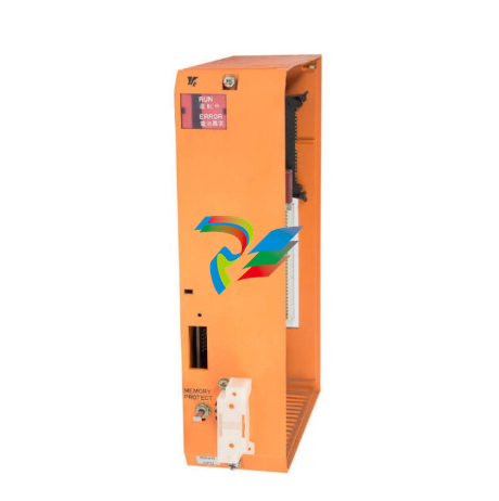
A-B1326AB High Performance AC Servomotors
Notes: e = Efficiency of leadscrew, e1 (90% typical) or gearbox, e2 (95% typical). G.R. = Ratio of motor speed to leadscrew speed. Jb = Leadscrew inertia (lb.-in.-s2). Jgb = Gearbox inertia at the motor shaft (lb.-in.-s2). Jm = Motor inertia (lb.-in.-s2). Jtjm = Total system inertia at the motor shaft (lb.-in.-s2). Lead = Movement of slide in inches per revolution of leadscrew. Nm = Motor velocity (rpm). Tb = Torque at leadscrew (lb.-in.). Thrust = Cutting force applied by slide/load on a workpiece (lbs). Tl = Load torque present at the motor shaft during accel (lb.-in.). Tm = Load torque required at the motor (lb.-in.). u = Table/slide sliding coefficient of friction (typically 0.03 to 0.2). V1 = Linear velocity of slide/load (IPM). W1 = Weight of slide and load (lbs.). θ = Angle of leadscrew position referenced from the horizontal axis (0°). (1) Friction torque generated by the weight of the table/slide and part/tool. (2) Torque required for thrust (cutting force) load. (3) Friction torque generated by the thrust (cutting force) load (approximation). (4) Safety factor to account for torque required to overcome seals, gib adjustments, etc. (10% of Tm, min.). (5) This term is for a non-counterbalanced, non-horizontal axis. (6) System inertia should not exceed 5 times the motor inertia.
Typical Leadscrew Data (Using Formulas from Previous Page) Torque at Lead to Produce 1000 lbs. Thrust Force 1. Divide the lb.-in. value shown by efficiency of screw to obtain corrected value
Lead Torque (in./rev) (lb.-in.) 0.200 31.84 0.250 39.80 0.300 47.77 Lead Torque (in./rev) (lb.-in.) 0.333 53.02 0.500 79.61 1.000 159.23
. For thrust other than 1000 lbs. Torque = Required Thrust 1000 x Torque at 1000 lbs.
Inertia of the Leadscrew 1. To determine total leadscrew inertia.
eadscrew Inertia = Total Leadscrew Length (in.) 10 x Inertia (per 10” length) Diameter Inertia (10” length) (inches) (lb.-in.-s2 ) 0.50 0.000048 0.75 0.00023 1.00 0.00072 1.25 0.0018 1.50 0.0038 1.75 0.0068 Diameter Inertia (10” length) (inches) (lb.-in.-s2) 2.00 0.0115 2.25 0.0184 2.50 0.0281 2.75 0.0412 3.00 0.0583 3.50 0.1080
. Formula to determine leadscrew inertia. Jb = 0.000073(1) x D4 x L where: D = Screw diameter in inches. L = Screw length in inches. (1) Leadscrew is assumed to be made of steel. If it is made of aluminum, the 0.000073 constant becomes 0.000024.
Inertia of the Slide/Table Reflected to the Motor per 1000 lbs. Weight 1. For slide/table weight other than 1000 lbs.
Slide/Table Inertia at Leadscrew = Actual Weight 1000 x Reflected Inertia (1000 lbs.) Lead Reflected Inertia (per 1000 lbs.) (in./rev) (lb.-in.-s2) 0.200 0.0026 0.250 0.0042 0.300 0.0060 Lead Reflected Inertia (per 1000 lbs.) (in./rev) (lb.-in.-s2 ) 0.333 0.0074 0.500 0.0167 1.000 0.0666
Typical Rack & Pinion System Data (Using Rack and Pinion Formulas from Previous Page)
Torque at Pinion to Produce 1000 lbs. Thrust Force 1. Divide lb.-in. value shown at pinion by gearbox ratio and efficiency to obtain required motor torque (Tm) 2. To determine pinion torque for other thrust values, divide the thrust by 1000 and multiply by the pinion torque shown for the proper radius. Pinion Radius1 Pinion Torque (inches) (lb.-in.) 0.5 526.3 1.0 1052.6 1.5 1578.9 1 Pinion efficiency of 95% assumed. Pinion Radius1 Pinion Torque (inches) (lb.-in.) 2.0 2105.3 3.0 3157.9 4.0 4210.5
Torque at Pinion to Move 1000 lbs. Total Table/Slide Weight 1. Divide the lb.-in. value shown at pinion by gearbox ratio and efficiency to obtain required motor torque (Tm) 2. To determine pinion torque for other weight values, divide the weight by 1000 and multiply by the pinion torque shown for the proper radius.
Torque at Drive Pulley/Roller 1 w/1000 lbs. Load 1. Divide lb.-in. value shown at the roller by the gearbox ratio, roller/ belt (e1) and gearbox (e2) efficiency to obtain required motor torque (Tm) 2. To determine pulley/roller torque for other load values, divide the load weight by 1000 and multiply by the pulley/roller torque shown for the appropriate radius.


.png)


