
A-B1326AB High Performance AC Servomotors
Basic Servomotor Description The 1326AB Servomotors are a family of high performance, three-phase, brushless AC synchronous motors designed by Allen-Bradley to meet the stringent requirements of servo system applications. This series of standard AC servomotors can be used with 1391 AC Servo Controllers. The performance parameters of these motors with selected amplifiers are listed on page 8. The typical speed-torque curves (see page 9) depict the operational envelope of these motor and controller combinations. Each motor has the following standard features:
• Permanent magnet rotor for increased servo response.
• Three-phase sinusoidal wound stator field for direct transfer of heat to ambient, and smooth operation at low speeds.
• Brushless resolver supplies position, commutation & velocity feedback information. This also provides durability in harsh environments by not having on-board electronics in the motor. 1391 A Quad B (optional) encoder output (up to 2048 ppr) is generated via resolver feedback.
• 100% continuous rated output torque at stall (zero rpm).
• Precision balance of 0.0005” (0.0127 mm) total peak-peak displacement.
• Vertical shaft up or down mounting.
• TENV construction.
• IP65 rated (when used with the Shaft Seal option) to withstand harsh environments. Motor is dust-tight and able to withstand pulsating water jets without liquid entering the motor. Important: 1326AB motors lose the IP 65 rating when externally mounted encoder/resolver feedback or blower packages are used.
• Normally closed thermal switch in the motor winding (rated 115V AC at 1A, 24V DC at 1A) provides thermal overload indication.
• Environmentally sealed power and feedback cable packages. Power and resolver feedback cables can be ordered as standard (flex), track (multi-flex) or extended length (ES).
• MIL spec connectors are standard.
• Ferrite magnets for cost effective performance.
• UL recognized insulation system (file # E57948).
Options available for the 1326AB include (option code designation or catalog number in parenthesis):
• Integral spring-set holding brakes with 90V DC coils (-A4, -A5, -A7) or 24V DC coils (-K4, -K5, -K7).
• Brake Power Supply (1326-MOD-BPS) converts 115V AC to the voltage needed for 90V DC brakes (-A4, -A5 and -A7).
• Shaft Oil Seal kits (1326AB-MOD-SSV-xx) for field installation of Viton shaft seals. Motor disassembly is not required.
• NEMA Inch (-11) or IEC metric flange mount (-21) with metric shafts.
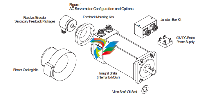
• Resolver Feedback Packages (1326AB-MOD-Vxxxx) provide 4.25” (108 mm) transducers which offer absolute/vernier or single brushless resolver feedback for use with Allen-Bradley 8600GP, IMC rack and S Class motion controllers. • Junction Box Kit (1326AB-MOD-RJxx) available with axially mounted connectors. Connector version allows the motor connectors to be brought out axially to the motor (rather than radially) without further wiring. • Secondary Feedback Mounting Kits (1326AB-MOD-Mx) for field installation of an Allen-Bradley Encoder (845H) or resolver. Using a 1326AB motor with a 1391B-ES (or 1391-DES) with A Quad B feedback (up to 2048 ppr) eliminates the need for encoder mounting. • Blower Cooling Kit (1326AB-MOD-G3, G4) provides air over cooling for up to 35% more torque output on most 1326AB “C” frame motors. The kit can be field mounted on the rear of 1326AB-Cxx motors (including motors with brakes). For motors using secondary motor mounted feedback (1326AB-MOD-M60), use option “G4.” • Cables for power (1326-CPxx . .) and feedback (1326-CFx . . - commutation, 1326-CEx . . - encoders) are available in lengths up to 100 ft .(30 m) for standard and high flex applications Power (1326ES-CPxx . .) and commutation (1326ES-CFx . .) cables over 100 ft. (30 m), up to 300 ft. (90 m) are available when using 1391B-ES or 1391-DES drives only. All kits are supplied as motor accessories and must be specified as a separate item.
Speed-Torque Curves Typical speed-torque curves for the standard 1326AB servomotors are contained on the following pages. Definitions of the terms used are provided below. Tc – rated torque of motor with windings at rated temperature and an ambient of 40°C. The controller is operating in a rated ambient of 60°C. Tp – the peak torque that can be produced by the motor/controller combination with both at rated temperature and the motor in a 40°C ambient and the controller in a 60°C ambient. Since 200% current torque peaks are common in many applications for optimal controller usage, the following curves show typical system performance. Higher peak torques are permissible where RMS torque is less than or equal to the rated torque (Tc). 1391B-ES/1391-DES operation is shown in the outer envelope and will show higher speed and 300% torque capability. Rated Speed – the operating speed of the controller and motor combination at which a minimum of 70% of continuous rated torque (Tc) can be developed. This point is defined with the motor at 25°C and controller operating in a 60°C ambient.
Rated Operation Area – boundary of speed-torque curve where the motor and controller combination may operate on a servo basis without exceeding the RMS rating of either. See page 31 for formula details.
-
 Hirschmann RS20-1600M2T1SDAEHH03.1.02 Rail Switch
 -
 Hirschmann BRS30-24TX Industrial Rail Switch
 -
 Hirschmann RSPM20-4T14T1EV9HHS999.9.99 Managed Ethernet Switch
 -
 Hirschmann BELDEN RS40-0009CCCCSDAPHH09.0.14 / RS400009CCCCSDAPHH09014
 -
Hirschmann RS40 Rail Switch RS40-0009CCCCSDAE
-
 Hirschmann BELDEN RS30-0802T1T1SDAP / RS300802T1T1SDAP Fully Managed Layer 2 Compact Rail Switch
 -
 Hirschmann BELDEN RS20-0800M2M2SDAUHH / RS200800M2M2SDAUHH
 -
 Hirschmann EAGLE30-04022O6TT999SCCY9HSE3F Industrial Firewall Router Switch
 -
 Hirschmann RS20-1600T1T1SDAEHH09.0.14 RS20 Rail Mount Ethernet Switch
 -
 Hirschmann EAGLE0200T1T1TDDY90000HHE05.3.03 Industrial Security Router
 -
Hirschmann - BELDEN MIPP-AD-1L9P
-
 HIRSCHMANN RSPM20-4Z64Z6TV9HHS9 942 106-999 RAIL SAFETY SWITCH
 -
 HIRSCHMANN FIBEROPTIC MODULE FIP P/N: OZDFIPG3T
 -
 HIRSCHMANN RS20-1600M2M2SDAUHH Ethernet rack-mounted switch
 -
 HIRSCHMANN BELDEN RS20-0400T1T1SDAEHH04.0.01 / RS200400T1T1SDAEHH04001
 -
HIRSCHMANN MM2-4FXM3 MICE Media Module
-
HIRSCHMANN RS20-0800M2M2SDAE Industrial Ethernet Rail Switch
-
 Hirschmann RS20-2400T1T1SDAP / RS20-2400T1T1SDAPHH05.0.02
 -
 GE MLJ1005B010H00C MLJ Digital Synchromism Check
 -
 ALSTOM MICROTECH DX21-M2 Digital Excitation Controller
 -
HIRSCHMANN BRS20-1200ZZZZ-STCY99HHSES
-
 HIRSCHMANN MM3-4FXM2 MICE Media Module
 -
Hirschmann RSB20-0800T1T1SAABHH 8Port ENet Rail Switch RSB20
-
 Hirschmann MACH102-8TP Ethernet Switch
 -
 SAACKE DDZ-M marine steam pressure atomizer
 -
 SAACKE SKV-A marine rotary cup atomizer
 -
 SAACKE Seavis HMI05e
 -
 Kollmorgen MMC-SD-2.0-230 Servo Drive 100-240VAC 2KW 10A Output 3PH 100-240VAC
 -
 Kollmorgen Servo drive CR10550
 -
 Kollmorgen AKD-P01207-NACN-0054 Servo Driver
 -
 Kollmorgen S406M-CA-036 Servostar
 -
.png) Kollmorgen AKD-B02407-NAAN-0000 Digital Servo Drive
Kollmorgen AKD-B02407-NAAN-0000 Digital Servo Drive -
 Kollmorgen SERVOSTAR S406AM-CA Digital Servo Drive
 -
 KOLLMORGEN SERVOSTAR 603-AS SERVO AMPLIFIER_SERVOSTAR603AS_S60301
 -
Kollmorgen S700 Servo Controller (S70602-NANANA-NA)
-
 Kollmorgen MPK411 controller
 -
 KOLLMORGEN MMC-SD-1.3-460-D Smart Drive
 -
 KOLLMORGEN AKM21C-CKB2AA-00 / AKM21CCKB2AA00 Servomotor
 -
 BECKHOFF AX5106-0000-0200 | Digital Compact Servo Drives 1-channel
 -
 BECKHOFF C3620-0000 INDUSTRIAL COMPUTER (MOTORSHELVES)
 -
 Beckhoff EK1960-0000 TwinSAFE Compact Controller
 -
 Beckhoff C6930-0050 Control Cabinet Industrial PC
 -
 Beckhoff CP7711-0001-0030 Industrial Computer Detection
 -
 Beckhoff CX1001-0111 Embedded PC CPU Module
 -
 Beckhoff C6017-0020 | Ultra-compact Industrial PC
 -
 Beckhoff EK1322 | 2-port EtherCAT P junction with feed-in
 -
 Beckhoff CP2219-0010 Panel
 -
 BECKHOFF C6015-0020 ULTRA COMPACT INDUSTRIAL PC
 -
 BECKHOFF CX2030-0120/Standard CPU Module Embedded PC Windows PLC controller
 -
 Beckhoff CP7721-1090-0020 Panel PC
 -
 Beckhoff PC CPU Module CX5130-0175
 -
 Beckhoff C6920-0050 Control Cabinet
 -
 Beckhoff EL6631 EtherCAT 2-Port Communication Interface, Profinet RT Controller
 -
 Beckhoff CP6202-0001-0060 touch screen panel PC
 -
 Beckhoff CP3916-1002-0000 Multi-Touch Control Panel
 -
 Beckhoff EP1809-0021 | EtherCAT Box, 16-channel digital input, 24 V DC, 3 ms, M8Preferred type
 -
 Beckhoff CX8190 PLC Embedded Industrial PC Ethernet Controller
 -
 Beckhoff CX2100-0914 Power Supply for External
 -
 Beckhoff Automation CP6906-0001-0000 HMI
 -
 Beckhoff EP7342-0002 Module
 -
 Beckhoff CX1020-0112 / CX1100-0910 / CX1020-N010 / CX1100-0003 Windows CPU
 -
 Beckhoff EP7211-0034 EtherCAT Box 1 Channel Motion Interface
 -
 Beckhoff C6240-0030 Control cabinet Industrial PC
 -
 beckhoff motherboard CB1052-0004 CB1052-0004
 -
 Beckhoff AX2006-AS Servo Drive / Variable Frequency Drive
 -
BECKHOFF CP6207-0001-0020 NSMP
-
 Beckhoff C6930-1142-0060 Industrial Computer
 -
 Beckhoff FC7501-0000 interface card
 -
 Beckhoff CX5140-0175 Embedded PC PLC CPU CX5140 Industrial Controller
 -
 Beckhoff CP7802-1100-0010: High-End IP65 Control Panel with DVI/USB Extended Interface
 -
BECKHOFF CP3716-1058-0010 CONTROL PANEL
-
 Beckhoff AX8108-0000 Single-Axis Module
 -
 Beckhoff CU8851-0000 | USB extension, USB Extended 2.0 receiver box
 -
Beckhoff C6017-0030 | Ultra-compact Industrial PC
-
 Beckhoff CX1001-0120/CX10010120.cx1000-n001.cx1000-n000 System Overview
 -
 Beckhoff CPU Module CX5140-0155/4GB CPU Module
 -
 Beckhoff CP6533-0001-005: Built-in Panel PC with High-Definition Multi-Touch Control
 -
 Beckhoff EL5042 | EtherCAT Terminal, 2-channel encoder interface, BiSS® C
 -
 Beckhoff C6920-1080-0040: Premium Control Cabinet Industrial PC
 -
 Beckhoff C6920-0060 | Control cabinet Industrial PC
 -
 Beckhoff Embedded-PC CX5010-1121
 -
 Beckhoff CB3050-0010 Mainboard Motherboard
 -
 Beckhoff PLC module CX1020-0000 Basic CPU module (service phase)
 -
 Beckhoff CP7812-1056-0010 15" Multitouch Display Control Panel
 -
 Beckhoff CX5120-0115 /2GB Controller Module
 -
 Beckhoff CP7201-1000-0000 Industrial Panel PC
 -
 Beckhoff Servo Motor AM8061-0JH1-0000
 -
 BECKHOFF CP6503-0001-0050 Built-in Panel PC
 -
Beckhoff CP3919-0010 Display G190ETN01.2 19" PCT V04. Multi-touch Control Panel
-
 Beckhoff CX5110-0112-9020/000368201 Embedded PC Intel Atom Processor
 -
 Beckhoff AX8206-0000 Dual-Axis Module
 -
Beckhoff Nail Operating Terminal CP7032-1031-0010
-
Beckhoff AM8042-0EH1-0000 Servomotor 4.10 Nm (M0), F4 (87 mm)
-
 Beckhoff EK9300 Beckhoff CPU Module
 -
Beckhoff CP3224-0020 Multitouch-Panel-PC
-
 Beckhoff CP2712-0000 12.1" 24VDC Touch Screen WMD0
 -
 BECKHOFF CX5240-0195 / 0000289234 Embedded PC 40 GB CFast Card
 -
 Beckhoff CP6932-1000-0000 Control Panel
 -
 BECKHOFF CX5120-0121 PLC Module
 -
 Beckhoff EL3218 | EtherCAT Terminal, 8-channel analog input
 -
Beckhoff C6640-0050 | Control cabinet Industrial PC
-
 Beckhoff Cx5130-0120/4GB Embedded-PC
 -
 BECKHOFF CX2030-0122 PLC PROCESSOR
 -
 BECKHOFF CX5020-0122 Controller Module
 -
 Beckhoff CP3915-0000 Multitouch Panel
 -
 BECKHOFF EL3014 | EtherCAT Terminal
 -
 BECKHOFF Industrial Computer c6920-1057-0030
 -
 Beckhoff CX5130-0141/4GB CX5130-0141 Embedded PC
 -
 Beckhoff C6240-1052-0040 4-086-06-3073 Industrial Computer
 -
 Beckhoff CX5140-0135 /4GB High-Performance Embedded Industrial PC
 -
 Beckhoff C6515-1001-0000 Industrial PC
 -
 Beckhoff AX5103-0000-0200 - Digital Compact Servo Drives
 -
 Beckhoff CX2030-0130-1003/4GB Basic CPU module
 -
 Beckhoff AX8620-0000 Power Supply Module
 -
 Beckhoff CX9020-0111 module with
 -
 Beckhoff EL7332 PLC Module
 -
 BECKHOFF CP7709-0001-0020 HMI
 -
 Beckhoff CX5120-0155/2GB Embedded PC
 -
 BECKHOFF CP7037-1037-0010 OPERATOR INTERFACE TOUCHSCREEN
 -
 Beckhoff EK9000 | ModbusTCP/UDP Bus Coupler
 -
 Beckhoff Touch Panel Screen CP6020 -0000-0000
 -
 Beckhoff CX2020-0121 Module FAST Shipping
 -
 Beckhoff CX2030-0125 Basic CPU Module
 -
 Beckhoff CP3918-0000 Multi-Touch 18.5" Control Panel
 -
 Automotion LC4A00010 DC BL Motor Control, ATS, Sub Assy, SCP, 115VAC,
 -
 500T-115VAC - VAS ENGINEERING - DORIC 500 SERIES DIGITAL TEMP INDICATOR
 -
 Honeywell X-DCS2000/EN Digital Integrated System Manager 50/60Hz 100-240V #4
 -
 Kollmorgen S60600 Servostar600 606-Fan 4 kVA, 6 A, 3 X 230 - 480 V


