
A-B1326AB High Performance AC Servomotors
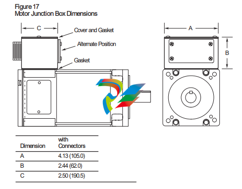
Motor Junction Box Kit (1326AB-MOD-RJxx) The Motor Junction Box Kit provides axially mounted connectors. The connector version allows the motor connectors to be brought out axially to the motor without further wiring. The IP65 rating of the motor is maintained when using this junction box. Dimensions for the junction box are shown in the following figure.
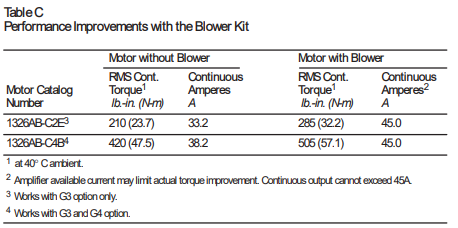
Blower Kits (1326AB-MOD-G3, G4) Two blower kits are available for use with 1326AB “C” Series AC Servomotors. The “G3” kit is designed for the “C2E” and “C4B” servomotors. The continuous current rating of all other “C” frame motors is too high to gain the benefit of the blower kit. The “G3” will not work on motors with a rear mounted encoder. The “G4” kit is designed for the “C4B” motor only. Each kit consists of an impedance protected fan (UL recognized, CSA approved), housing, grill guard and necessary hardware. Important: The IP 65 rating of the motor is not maintained when using this option. Specifications Input Voltage 220/240V AC, 50/60 Hz., single-phase Line Amperes 0.15 / 0.14 Locked Rotor Amperes 0.23 / 0.23 Fan Output 240 CFM Air Inlet Clearance 6 inches (152.4 mm) Weight 4 lbs. (1.81 kg) The following table illustrates the operational improvements realized when the blower kit is installed on the motors shown. Refer to Figure 18 for dimensions.
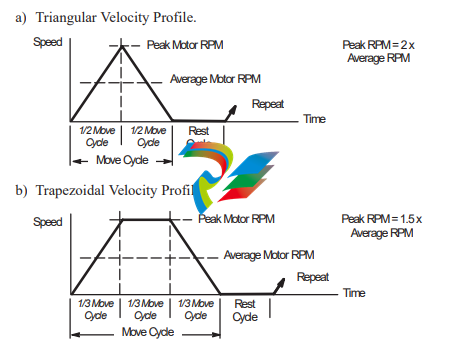
The following steps are a general guide designed to assist in servomotor selection. Formulas provided on the following pages should be used in conjunction with the steps below to determine correct motor sizing. For further assistance, complete the appropriate Application Data Sheet (pages 38-43) and contact your local Allen-Bradley Sales Office. 1. Determine the motor speed requirements. Based on the power train configuration of your application (leadscrew, rack and pinion, conveyor) determine the average and peak rpm of the servomotor. Choose the velocity profile that provides the closest approximation of your cycle.
2. Determine the minimum continuous motor torque required. Calculate motor torque (Tm) using the formulas on page 32, 34 or 36. 3. Determine the peak motor torque required to accelerate the load. If the motor must accelerate within a specified time, determine the system inertia using the formula sheets for your specific power train configuration, otherwise go to step 5. Use the time (Time) to achieve peak rpm, change in rpm (∆rpm), power train inertia (System Inertia) and load torque (Tl) in one of the two formulas that follow: System Inertia in lb.-ft.2 Peak Torque = System Inertia x ∆rpm 308 x Time (to accelerate) + Tl where: Peak Torque = total motor torque required to accelerate the load in lb.-ft. System Inertia = total system inertia (including motor) in lb.-ft.2 Time = acceleration time (in seconds) Tl = load torque present at the motor shaft during accel in lb.-ft. ∆rpm = change in motor velocity during acceleration time
where: Peak Torque = total motor torque required to accelerate the load in lb.-in. System Inertia = total system inertia in lb.-in.-s2 (listed as Jtjm on formula sheets) Time = acceleration time (in seconds) Tl = load torque present at the motor shaft during accel in lb.-in. ∆rpm = change in motor velocity during acceleration time. 4. If the motors total time to accelerate/decelerate (t1 + t3) exceeds 20% of the total cycle time (t1+t2+t3+t4), determine the motors average torque with the formula shown
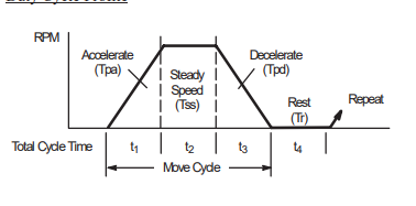
Trms The motors RMS or average torque over the duty cycle. (Expressed in lb.-in. or lb.-ft. The same units must be used throughout the formula.) Tpa Motor peak torque to accelerate to maximum speed. (Expressed in lb.-in. or lb.-ft. The same units must be used throughout the formula.) Tss Motor torque present at the motor shaft during constant speed segment. (Expressed in lb.-in. or lb.-ft. The same units must be used throughout the formula.) Tpd Motor peak torque to decelerate to zero speed. (Expressed in lb.-in. or lb.-ft. The same units must be used throughout the formula.) Tr Torque when motor is at zero speed (typically is Tss). t1, t2, t3, t4 Time for each portion of the duty cycle in seconds. Tpa2 x t1 + Tss2 x t2 + Tpd2 x t3 + Tr2 x t4 t1 + t2 + t3 + t4 Trms = 5. To select a servomotor: a) Select a motor with maximum speed capability of at least the peak rpm calculated in step 1. b) Select a motor with continuous torque capability equal to or greater than the value determined in step 2 or 4, whichever is greater. c) Select a motor with the capability to supply peak torque as determined in step 3, up to the maximum speed determined in step 1.
Servomotor Driven Leadscrew Formulas
Where: Notes: e = Efficiency of leadscrew, e1 (90% typical) or gearbox, e2 (95% typical). G.R. = Ratio of motor speed to leadscrew speed. Jb = Leadscrew inertia (lb.-in.-s2). Jgb = Gearbox inertia at the motor shaft (lb.-in.-s2). Jm = Motor inertia (lb.-in.-s2). Jtjm = Total system inertia at the motor shaft (lb.-in.-s2). Lead = Movement of slide in inches per revolution of leadscrew. Nm = Motor velocity (rpm)
Tb = Torque at leadscrew (lb.-in.). Thrust = Cutting force applied by slide/load on a workpiece (lbs). Tl = Load torque present at the motor shaft during accel (lb.-in.). Tm = Load torque required at the motor (lb.-in.). u = Table/slide sliding coefficient of friction (typically 0.03 to 0.2). V1 = Linear velocity of slide/load (IPM). W1 = Weight of slide and load (lbs.). θ = Angle of leadscrew position referenced from the horizontal axis (0°).
-
 Hirschmann RS20-1600M2T1SDAEHH03.1.02 Rail Switch
 -
 Hirschmann BRS30-24TX Industrial Rail Switch
 -
 Hirschmann RSPM20-4T14T1EV9HHS999.9.99 Managed Ethernet Switch
 -
 Hirschmann BELDEN RS40-0009CCCCSDAPHH09.0.14 / RS400009CCCCSDAPHH09014
 -
Hirschmann RS40 Rail Switch RS40-0009CCCCSDAE
-
 Hirschmann BELDEN RS30-0802T1T1SDAP / RS300802T1T1SDAP Fully Managed Layer 2 Compact Rail Switch
 -
 Hirschmann BELDEN RS20-0800M2M2SDAUHH / RS200800M2M2SDAUHH
 -
 Hirschmann EAGLE30-04022O6TT999SCCY9HSE3F Industrial Firewall Router Switch
 -
 Hirschmann RS20-1600T1T1SDAEHH09.0.14 RS20 Rail Mount Ethernet Switch
 -
 Hirschmann EAGLE0200T1T1TDDY90000HHE05.3.03 Industrial Security Router
 -
Hirschmann - BELDEN MIPP-AD-1L9P
-
 HIRSCHMANN RSPM20-4Z64Z6TV9HHS9 942 106-999 RAIL SAFETY SWITCH
 -
 HIRSCHMANN FIBEROPTIC MODULE FIP P/N: OZDFIPG3T
 -
 HIRSCHMANN RS20-1600M2M2SDAUHH Ethernet rack-mounted switch
 -
 HIRSCHMANN BELDEN RS20-0400T1T1SDAEHH04.0.01 / RS200400T1T1SDAEHH04001
 -
HIRSCHMANN MM2-4FXM3 MICE Media Module
-
HIRSCHMANN RS20-0800M2M2SDAE Industrial Ethernet Rail Switch
-
 Hirschmann RS20-2400T1T1SDAP / RS20-2400T1T1SDAPHH05.0.02
 -
 GE MLJ1005B010H00C MLJ Digital Synchromism Check
 -
 ALSTOM MICROTECH DX21-M2 Digital Excitation Controller
 -
HIRSCHMANN BRS20-1200ZZZZ-STCY99HHSES
-
 HIRSCHMANN MM3-4FXM2 MICE Media Module
 -
Hirschmann RSB20-0800T1T1SAABHH 8Port ENet Rail Switch RSB20
-
 Hirschmann MACH102-8TP Ethernet Switch
 -
 SAACKE DDZ-M marine steam pressure atomizer
 -
 SAACKE SKV-A marine rotary cup atomizer
 -
 SAACKE Seavis HMI05e
 -
 Kollmorgen MMC-SD-2.0-230 Servo Drive 100-240VAC 2KW 10A Output 3PH 100-240VAC
 -
 Kollmorgen Servo drive CR10550
 -
 Kollmorgen AKD-P01207-NACN-0054 Servo Driver
 -
 Kollmorgen S406M-CA-036 Servostar
 -
.png) Kollmorgen AKD-B02407-NAAN-0000 Digital Servo Drive
Kollmorgen AKD-B02407-NAAN-0000 Digital Servo Drive -
 Kollmorgen SERVOSTAR S406AM-CA Digital Servo Drive
 -
 KOLLMORGEN SERVOSTAR 603-AS SERVO AMPLIFIER_SERVOSTAR603AS_S60301
 -
Kollmorgen S700 Servo Controller (S70602-NANANA-NA)
-
 Kollmorgen MPK411 controller
 -
 KOLLMORGEN MMC-SD-1.3-460-D Smart Drive
 -
 KOLLMORGEN AKM21C-CKB2AA-00 / AKM21CCKB2AA00 Servomotor
 -
 BECKHOFF AX5106-0000-0200 | Digital Compact Servo Drives 1-channel
 -
 BECKHOFF C3620-0000 INDUSTRIAL COMPUTER (MOTORSHELVES)
 -
 Beckhoff EK1960-0000 TwinSAFE Compact Controller
 -
 Beckhoff C6930-0050 Control Cabinet Industrial PC
 -
 Beckhoff CP7711-0001-0030 Industrial Computer Detection
 -
 Beckhoff CX1001-0111 Embedded PC CPU Module
 -
 Beckhoff C6017-0020 | Ultra-compact Industrial PC
 -
 Beckhoff EK1322 | 2-port EtherCAT P junction with feed-in
 -
 Beckhoff CP2219-0010 Panel
 -
 BECKHOFF C6015-0020 ULTRA COMPACT INDUSTRIAL PC
 -
 BECKHOFF CX2030-0120/Standard CPU Module Embedded PC Windows PLC controller
 -
 Beckhoff CP7721-1090-0020 Panel PC
 -
 Beckhoff PC CPU Module CX5130-0175
 -
 Beckhoff C6920-0050 Control Cabinet
 -
 Beckhoff EL6631 EtherCAT 2-Port Communication Interface, Profinet RT Controller
 -
 Beckhoff CP6202-0001-0060 touch screen panel PC
 -
 Beckhoff CP3916-1002-0000 Multi-Touch Control Panel
 -
 Beckhoff EP1809-0021 | EtherCAT Box, 16-channel digital input, 24 V DC, 3 ms, M8Preferred type
 -
 Beckhoff CX8190 PLC Embedded Industrial PC Ethernet Controller
 -
 Beckhoff CX2100-0914 Power Supply for External
 -
 Beckhoff Automation CP6906-0001-0000 HMI
 -
 Beckhoff EP7342-0002 Module
 -
 Beckhoff CX1020-0112 / CX1100-0910 / CX1020-N010 / CX1100-0003 Windows CPU
 -
 Beckhoff EP7211-0034 EtherCAT Box 1 Channel Motion Interface
 -
 Beckhoff C6240-0030 Control cabinet Industrial PC
 -
 beckhoff motherboard CB1052-0004 CB1052-0004
 -
 Beckhoff AX2006-AS Servo Drive / Variable Frequency Drive
 -
BECKHOFF CP6207-0001-0020 NSMP
-
 Beckhoff C6930-1142-0060 Industrial Computer
 -
 Beckhoff FC7501-0000 interface card
 -
 Beckhoff CX5140-0175 Embedded PC PLC CPU CX5140 Industrial Controller
 -
 Beckhoff CP7802-1100-0010: High-End IP65 Control Panel with DVI/USB Extended Interface
 -
BECKHOFF CP3716-1058-0010 CONTROL PANEL
-
 Beckhoff AX8108-0000 Single-Axis Module
 -
 Beckhoff CU8851-0000 | USB extension, USB Extended 2.0 receiver box
 -
Beckhoff C6017-0030 | Ultra-compact Industrial PC
-
 Beckhoff CX1001-0120/CX10010120.cx1000-n001.cx1000-n000 System Overview
 -
 Beckhoff CPU Module CX5140-0155/4GB CPU Module
 -
 Beckhoff CP6533-0001-005: Built-in Panel PC with High-Definition Multi-Touch Control
 -
 Beckhoff EL5042 | EtherCAT Terminal, 2-channel encoder interface, BiSS® C
 -
 Beckhoff C6920-1080-0040: Premium Control Cabinet Industrial PC
 -
 Beckhoff C6920-0060 | Control cabinet Industrial PC
 -
 Beckhoff Embedded-PC CX5010-1121
 -
 Beckhoff CB3050-0010 Mainboard Motherboard
 -
 Beckhoff PLC module CX1020-0000 Basic CPU module (service phase)
 -
 Beckhoff CP7812-1056-0010 15" Multitouch Display Control Panel
 -
 Beckhoff CX5120-0115 /2GB Controller Module
 -
 Beckhoff CP7201-1000-0000 Industrial Panel PC
 -
 Beckhoff Servo Motor AM8061-0JH1-0000
 -
 BECKHOFF CP6503-0001-0050 Built-in Panel PC
 -
Beckhoff CP3919-0010 Display G190ETN01.2 19" PCT V04. Multi-touch Control Panel
-
 Beckhoff CX5110-0112-9020/000368201 Embedded PC Intel Atom Processor
 -
 Beckhoff AX8206-0000 Dual-Axis Module
 -
Beckhoff Nail Operating Terminal CP7032-1031-0010
-
Beckhoff AM8042-0EH1-0000 Servomotor 4.10 Nm (M0), F4 (87 mm)
-
 Beckhoff EK9300 Beckhoff CPU Module
 -
Beckhoff CP3224-0020 Multitouch-Panel-PC
-
 Beckhoff CP2712-0000 12.1" 24VDC Touch Screen WMD0
 -
 BECKHOFF CX5240-0195 / 0000289234 Embedded PC 40 GB CFast Card
 -
 Beckhoff CP6932-1000-0000 Control Panel
 -
 BECKHOFF CX5120-0121 PLC Module
 -
 Beckhoff EL3218 | EtherCAT Terminal, 8-channel analog input
 -
Beckhoff C6640-0050 | Control cabinet Industrial PC
-
 Beckhoff Cx5130-0120/4GB Embedded-PC
 -
 BECKHOFF CX2030-0122 PLC PROCESSOR
 -
 BECKHOFF CX5020-0122 Controller Module
 -
 Beckhoff CP3915-0000 Multitouch Panel
 -
 BECKHOFF EL3014 | EtherCAT Terminal
 -
 BECKHOFF Industrial Computer c6920-1057-0030
 -
 Beckhoff CX5130-0141/4GB CX5130-0141 Embedded PC
 -
 Beckhoff C6240-1052-0040 4-086-06-3073 Industrial Computer
 -
 Beckhoff CX5140-0135 /4GB High-Performance Embedded Industrial PC
 -
 Beckhoff C6515-1001-0000 Industrial PC
 -
 Beckhoff AX5103-0000-0200 - Digital Compact Servo Drives
 -
 Beckhoff CX2030-0130-1003/4GB Basic CPU module
 -
 Beckhoff AX8620-0000 Power Supply Module
 -
 Beckhoff CX9020-0111 module with
 -
 Beckhoff EL7332 PLC Module
 -
 BECKHOFF CP7709-0001-0020 HMI
 -
 Beckhoff CX5120-0155/2GB Embedded PC
 -
 BECKHOFF CP7037-1037-0010 OPERATOR INTERFACE TOUCHSCREEN
 -
 Beckhoff EK9000 | ModbusTCP/UDP Bus Coupler
 -
 Beckhoff Touch Panel Screen CP6020 -0000-0000
 -
 Beckhoff CX2020-0121 Module FAST Shipping
 -
 Beckhoff CX2030-0125 Basic CPU Module
 -
 Beckhoff CP3918-0000 Multi-Touch 18.5" Control Panel
 -
 Automotion LC4A00010 DC BL Motor Control, ATS, Sub Assy, SCP, 115VAC,
 -
 500T-115VAC - VAS ENGINEERING - DORIC 500 SERIES DIGITAL TEMP INDICATOR
 -
 Honeywell X-DCS2000/EN Digital Integrated System Manager 50/60Hz 100-240V #4
 -
 Kollmorgen S60600 Servostar600 606-Fan 4 kVA, 6 A, 3 X 230 - 480 V


