
Honeywell 5704 Control System: Technical Summary
Honeywell 5704 Control System: Technical Summary
Introduction & System Concept
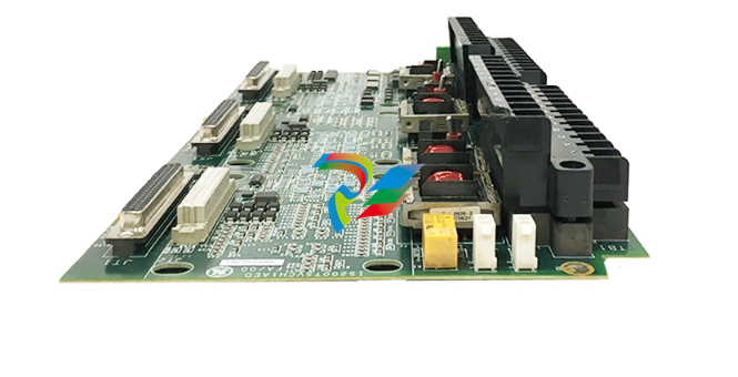
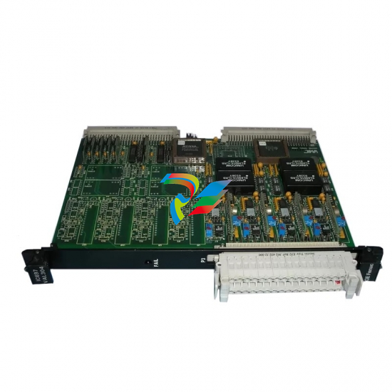
This document provides a technical summary of the Honeywell 5704 Control System, a component of the broader System 57 family. The 5704 system is a microprocessor-based, modular control system designed to monitor industrial gas detectors. It provides display, alarm, and control functionalities for up to 64 channels in a standard 19-inch rack. Its primary purpose is to process signals from field-mounted sensors and initiate alarms or control actions based on pre-configured setpoints.
System Architecture & Components
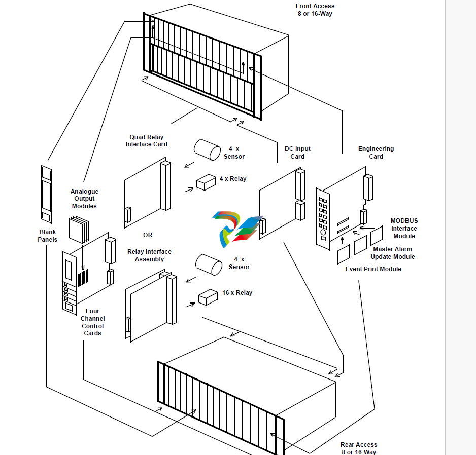
The 5704 system is built on a modular, rack-based platform, allowing for flexible configurations tailored to specific application needs. The core components are housed in either a full 19" or half-width 19" sub-rack, available in 3U (rear access wiring) or 6U (front access wiring) formats.
The main components include:
Four Channel Control Card (Part No. 05704-A-0144 / 0145): This is the central processing unit for a group of four sensors. It is a 1-inch wide, plug-in module responsible for sensor drive, signal processing, gas level display, and alarm logic. Two main versions are available:
Catalytic Input Card: For use with catalytic bead (pellistor) combustible gas sensors.
4-20mA Input Card: For use with any gas detector or transmitter that provides a standard 4-20mA analog signal.
Quad Relay Interface Card (Part No. 05704-A-0121): This card serves as the physical interface between a Four Channel Control Card and the field wiring. It provides terminals for sensor connections and includes four standard single-pole changeover (SPCO) relays for alarm outputs.
Expansion Relay Card: To increase the number of physical relay outputs, an Expansion Relay Card can be attached to the Quad Relay Interface Card, forming a Relay Interface Assembly. This expands the relay count from four to sixteen for a group of four channels.
Engineering Card (Part No. 05701-A-0361): A single Engineering Card is fitted in each rack. It serves as the primary user interface for commissioning, calibration, and maintenance. It features push-buttons for local operation and an RS232 serial port for connection to a PC (for configuration software) or a printer.
DC Input Card: Manages the 24V DC power distribution to the rack's backplane.
Optional Modules: The system can be expanded with modules that plug into the Engineering Card, such as a Modbus Interface Module (RS232 or RS485/422) for digital communication with host systems, or an Event Printing Module.
Key Features & Capabilities
High-Density Monitoring: Provides up to 64 channels (16 x Four Channel cards) in a standard 19" rack.
Flexible Inputs: Supports both catalytic bridge sensors and industry-standard 4-20mA loop-powered sensors or transmitters.
Advanced Alarm Handling: The system can be configured for complex alarm logic beyond simple individual channel alarms, including:
Zoned Alarms: An alarm from any sensor within a designated physical area.
Master Alarms: A common alarm for any designated channel within a single rack.
Voted Alarms: An alarm that requires simultaneous alarms from multiple channels within a group before activating.
Onboard Relays: Each group of four channels has access to at least four relays, expandable to sixteen, which can be configured for various alarm levels (A1, A2, A3), fault conditions, or inhibit status. Relays can be set as latching/non-latching and normally energized/de-energized.
User Interface: Each Control Card has a backlit LCD for displaying the gas concentration (via digital readout and analog bargraph), channel status, and alarm messages. Status LEDs provide at-a-glance indication of alarms, faults, and inhibit conditions for each channel.
Maintenance & Calibration: All maintenance and calibration functions (Zero, Span, 1st Span for new catalytic sensors) are accessed via the common Engineering Card, which requires an "Engineering Key" to unlock adjustment functions, preventing unauthorized changes.
-
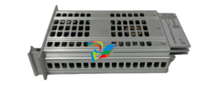
 369B1844G5004 High-Performance Industrial Control Module
 -
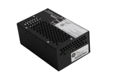
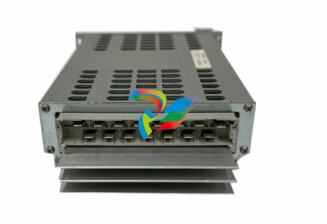
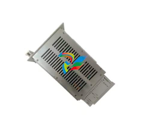
 208D9845P0008 DC stabilized power supply module
 -
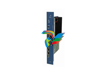
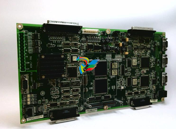
 GE 369B1860G0030 Intelligent DPU Controller Module
 -
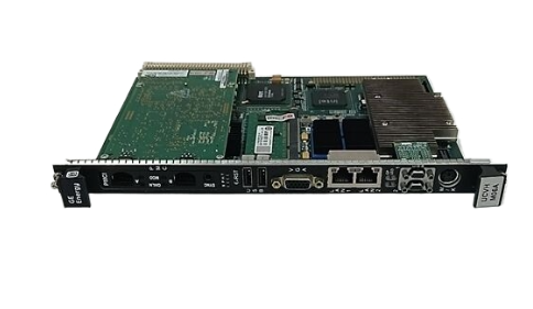
 PACSystems™ IC695CPE400 RX3i 64 MB Rackless CPU with Field Agent Quick Start
 -
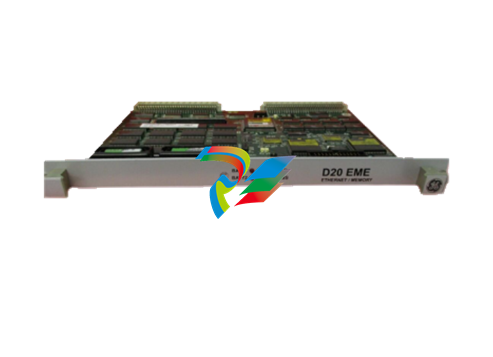
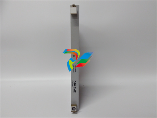
 D20EME10BASE-T 820-0474 Ethernet Communication Expansion Module
 -
 IC800SSI228RD2-CE Servo controller
 -
 Jump-type DC power distribution card IS200JPDMG1ACC S1AT005
 -
 Turbine control system module IS200TSVCH1AED
 -
 IS200TTURH1CCC terminal turbine plate
 -
 IS200TSVCH1ADC S1CX01H Servo valve interface terminal board
 -
 IS200TRPGH1BDD S1C5029 Terminal Relay Panel Module
 -
 Secure analog I/O package IS220YAICS1AL
 -
 IS420PPNGH1A GE Controller Gateway Module
 -
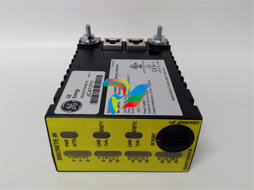
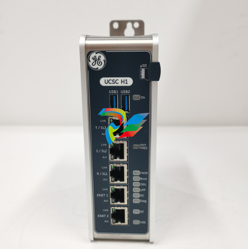 UCSC compact quad-core controller IUCSC H1 IS420UCSCH1A-B
 -
 The IC698CPE010 is a Central Processing Unit from the GE Fanuc RX7i series
 -
 IC697VDD100 Digital Output Module
 -
 V7768-320000 3509301007768-320000A0 6U single-board computer
 -
 TB43225-AF14 3 Pole Circuit Breaker
 -
 Induction terminal board IS410TRLYS1B
 -
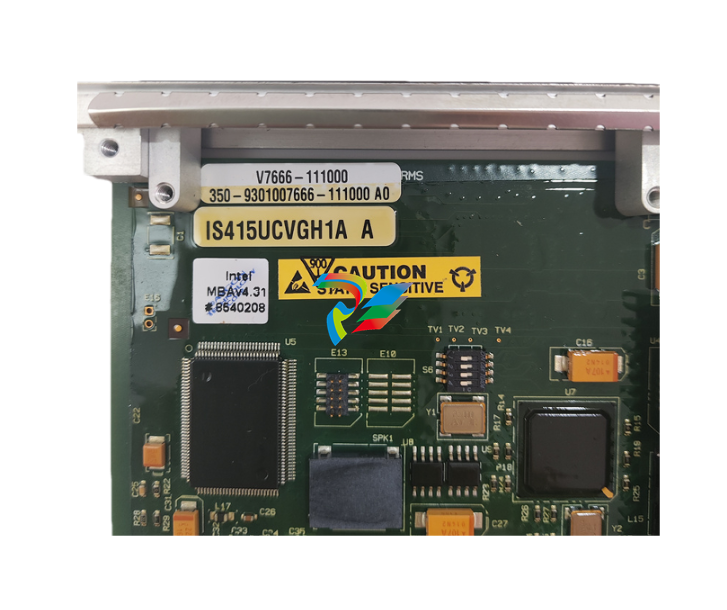 IS415UCVGH1A V7666-111000 Redundant I/O or control module
 -
 Servo motor controller IC800SSI216RD2
 -
IS210MACCH1AKH IS200WEMDH1ABA Interface Board
-
 VMIVME-5565-010000 332-015565-010000 P Reflective Memory (RFM) Node Card
 -
 IS220PDOAH1B Contact Output Module
 -
IC698CHS009 Rx7i PACsystem I/O Rack Module
-
 IS420PUAAH1A Universal input/output module
 -
 Flame detector RS-FS-9001 362A1052P004
 -
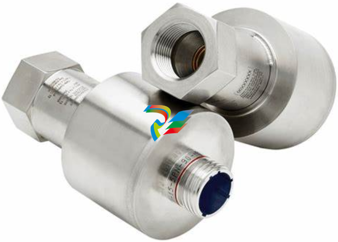
 Hydran 201Ti Mark IV Essential DGA monitoring for transformers
 -
 IS210BPPBH2BMD Redundant Power Supply Module for Mark VIe Turbine Control
 -
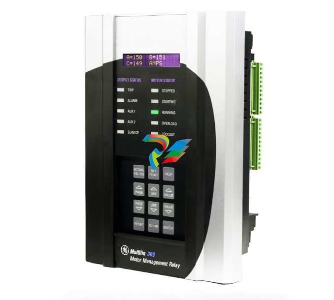 369-HI-0-M-0-0-0-E 369 Motor Management Relay
 -
 S739DVT Digital Valve Trip Module
 -
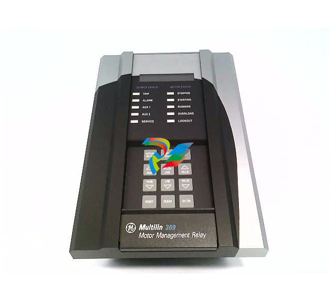 369-HI-R-M-F-E-H-E Motor Management Relay
 -
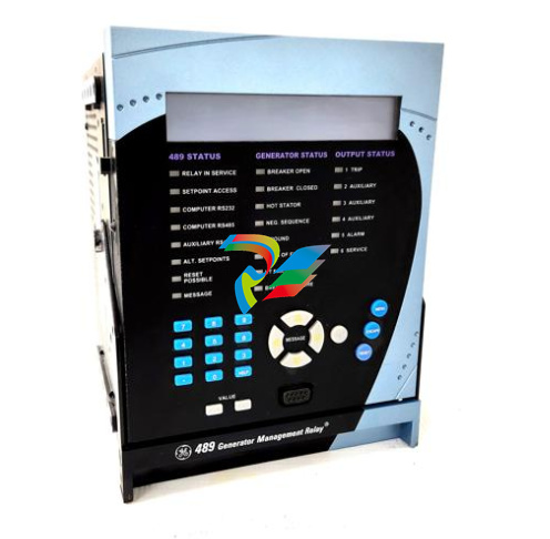 489-P5-HI-A20-E Multilin Relays
 -
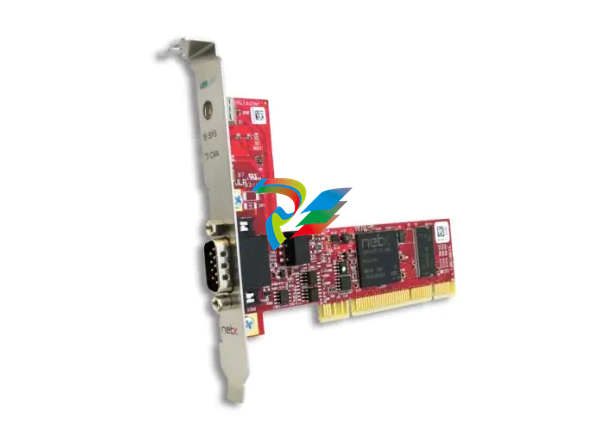 PC Card CIFX 50-CO – PCI
 -
 PC000087524/01 Power module
 -
 SR469-P5-H-A20-T Multi-Function Motor Protection Relay
 -
 WES5120 2340-21005 On site controller main station unit
 -
 WES5120 2340-21003 Analog output module
 -
 Alstom IRVI20 - REGULATION INTERFACE BOARD
 -
 ABB DRIVEMONITOR VERSION 4000 DRIVE MODULE RBOX316-ABB-00
 -
D20MIC10BASE-T 820-0756 Network card
-
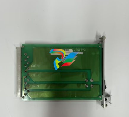
 WES13-3 5167-0001-0210 CPU/Auxiliary Control board
 -
 WES13-3 2508-21001 Embedded digital module
 -
D20ME 526-2005-216943 control module
-
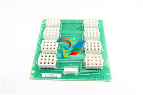
 D20EME 0526-21170-1 Enhanced Master Communications Module for D20 Substation RTUs
 -
.jpg) 2400-21004 / 2010-3101-0442 – Redundant Power Supply Module for Mark VIe Turbine Control
2400-21004 / 2010-3101-0442 – Redundant Power Supply Module for Mark VIe Turbine Control -
 PACSystems™ IC695CPE400 RX3i 64 MB
 -
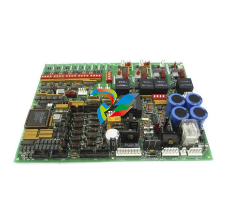 DS200DCFBG2BNC DC2000 DC Feedback Board
 -
 OLDI Ethernet interface module 56SAM-844
 -
IS200BPPBH2CAA Mark VIe Power Supply Module
-
 IS210MACCH2AEG Motor Control and Communication Module
 -
 IS210MACCH2AGG Mark VIe Speedtronic Turbine Control Module
 -
 IS200AEPAH1AFD Printed circuit board
 -
IS200AEPAH1ACB Analog I/O Module
-
 IS200WREAS1ADB AERO TRIP TB DBRD sub-board
 -
 IS200WETAH1AEC large board component made Mark VI system
 -
 IS200AEPAH1AHD A High-Precision Excitation Control Board for Turbine Systems
 -
 IS200WEMAH1AEA Control board
 -
IS210MACCH1AGG processor card
-
IS230TNRLH1B Discrete Output Modular Assembly
-
 Mark V Series DS200PCCAG1ACB PCB Power Connect Card
 -
 DS200SI0CG1AEA Instantaneous overcurrent card
 -
 DS200SHVMG1AGE Analog I/O board
 -
 DS200SI0CG1A6A Input/Output Module
 -
 DS200SHVMG1AFE SCR High Voltage Interface Board
 -
 DS200RT8AG3AHC Relay Output Terminal Board
 -
 DS200FSAAG1ABA PCB Field Supply Gate Amplifier Board
 -
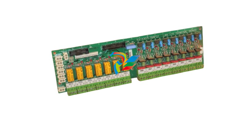 531X307LTBAFG1 F31X307LTBA LAN I/O Terminal Board
 -
ABB AFS670 19" Ruggedized Switch AFS670-EREEDDDSSEEEEEEEPZYX05.1.0
-
 NI Controller for VXI VXIPC-871B
 -
 IS200EPMCH1GE Mark VIe Patch Cord Power Distribution Card
 -
 VMICPCI-7632-03310 IS215UCCAH3A 350-657362-003310J GE gas turbine system control processor board
 -
 WEA13-13 2508-21001 Control Module / I/O Board
 -
WES5120 2340-21004 Controller Main Module
-
 WES5120 2340-21006 Field Controller Master Unit Module
 -
WESDAC D20ME 18-MAR-13 Excitation Control Module
-
 D20 EME 2400-21004 Ethernet communication and expansion module
 -
 GE DS3800XTFP1E1C Thyristor Fan Out Board Brand
 -
 GE SR745-W2-P1-G1-HI-A-L-R-E Feeder protection relay
 -
 GE IS230TNDSH2A Discrete Output Relay Module Brand
 -
 GE Fanuc IS200TDBSH2ACC Mark VI Terminal Board Brand
 -
 GE PMC-0247RC-282000 350-93750247-282000F Disk Drive
 -
GE PMC-0247RC-282000 350-93750247-282000F Disk Drive
-
 GE VMIVME-1150 Serial Communications Controller
 -
 GE VMIVME-5576 Fiber-Optic Reflective Memory with Interrupts
 -
GE VMIC Isolated Digital Output VMIVME-2170A
-
 GE MULTILIN 760 FEEDER MANAGEMENT RELAY 760-P5-G5-S5-HI-A20-R-E
 -
GE IS200AEPAH1BKE IS215WEPAH2BB Printed circuit board
-
 GE IS210BPPCH1A Mark VIe I/O Pack Processor Card
 -
 GE IS220PRTDH1A 336A4940CSP6 High-Performance RTD Input Module
 -
GE IS220PDIAH1BE 336A5026ADP4 Discrete Input Module
-
 GE IS420ESWBH3A IONET Switch Module
 -
 GE 516TX 336A4940DNP516TX 16-port Ethernet switch
 -
 GE EVMECNTM13 Embedded control module
 -
GE EVPBDP0001 EVPBDP032 control module
-
 GE Hydran M2-X Enhanced Monitoring with Extended Sensor Life
 -
 GE UR6CH Digital I/O Module
 -
 GE IC695CPU315-CD Central processing unit
 -
 GE 531X305NTBAMG1 DR Terminal Board
 -
 GE 531X305NTBALG1 NTB/3TB Terminal Board 531X Series
 -
 GE 531X305NTBAJG1 NTB/3TB Terminal Board.
 -
GE 531X305NTBAHG1 NTB/3TB Terminal Board 531X
-
 GE 531X305NTBAEG1 is a PCB that functions as a DR terminal board.
 -
General Electric 531X305NTBACG1 NTB/3TB Terminal Board 531X
-
 GE Digital Energy D20 Analog Input Module
 -
 GE 94-164136-001 main board Control board
 -
 GE 269 PLUS-D/O-100P-125V Digital motor relay
 -
 GALIL DMC-9940 High-performance motion controller
 -
FUJI NP1BS-08 base plate
-
 FUJI NP1Y32T09P1 Transistor drain type digital output module
 -
 FUJI NP1Y16R-08 Digital Output Module
 -
 FUJI NP1X3206-A High-speed digital input module
 -
 FUJI NP1AYH4I-MR current output module
 -
 FUJI NP1S-22 Power module redundancy
 -
 FUJI RPXD2150-1T servo drive module
 -
 FUJI FVR008E7S-2UX Ac frequency converter
 -
 FUJI Ac frequency converter FVR008E7S-2
 -
 FUJI FVR004G5B-2 Small general-purpose frequency converter
 -
 FUJI A50L-2001-0232 Industrial control module
 -
 FUJI A50L-001-0266#N High-performance servo amplifier
 -
 Honeywell FS7-2173-2RP Gas sensor
 -
 Honeywell 10106/2/1 Digital Input Module in Stock
 -
FRCE SYS68K CPU-40 B/16 PLC core processor module
-
Foxboro FBM I/O cards PBCO-D8-009
-
 Foxboro AD916AE Digital Control System (DCS) Module
 -
 GE SR750-P5-G5-S5-HI-A20-R-E Multilin Relay
 -
.jpg) FOXBORO H90 H90C9AA0117S Industrial Computer Workstation
FOXBORO H90 H90C9AA0117S Industrial Computer Workstation -
FOXBORO RH928AW | I/A Series Relay Output Module


